


If I eliminate the DZ1000 controllers, how do I know the turnouts are in the correct positions? I could AND the appropriate turnout switch positions. When the AND is satisfied, I could light a remote Lane Status board I could see.
In your most recent examples for controlling TRACK POWER with non-mechanical latching relays:
The relay modules, such as the eBay example you give, need a constant power source typically labeled DC+ and DC-. This must always be supplied...even when initially turned on with not momentary latch command. If I understand your hookup, it appears you momentarily apply DC+ (or DC-) to the module. This won't work. You apply constant DC+ and DC-...and then to latch the relay you momentarily apply DC+ (if a high-trigger) or DC- (if a low-trigger) to the relay's trigger input line. The relay then latches ON until power is removed from the module by removing either DC+ or DC-.
As for monitoring turnout position, it's hard to imagine a "simpler" method than what the DZ1000 itself uses in the controller. I don't know the dimensions of the controller relative to your panel space but since you know how many controllers you need it seems you could assemble a panel with a compact matrix of push-buttons and LEDs in much less space than using the stock controller assemblies. As shown in their schematic you could also forego their push-buttons and simply use the LED circuit (2 LEDs, 2 resistors) to monitor position. Obviously this would save a lot of panel space.
That's an interesting idea to implement some kind of logic circuit (e.g., AND) as some kind of fault detection. I suggest you defer this discussion until the relay issue is resolved. There are other similar finishing touches that will need discussion ... such as the the DCS watchdog issue I mentioned earlier when powering up a new track block.
Stan - Seems like we're on the same page. Yes, I realized my error for the non-mechanical latching relay's need for constant DC power. The outstanding question is can I simply just connect all the triggers together and connect to the momentary switch or do they need to be isolated from each other ?
Regarding DZ1000 controller real estate. The panel is pre-drilled years ago. I had originally allocated 8 space but I used two recently for another modification. I believe the remaining 6 spaces are better reserved for future use.
I think we are almost at the conceptual design.
The turnout status/fault detection display would be remotely mounted, visible and located closer to the yard.
@shorling posted:..The outstanding question is can I simply just connect all the triggers together and connect to the momentary switch or do they need to be isolated from each other ?
If I understand your question, connecting all the triggers together would simply cause all 8 relays to latch together (in response to the momentary button press) even if you only want 1 of the 8 to latch! So, yes, the triggers must be isolated from each other.

But, in addition to isolating the triggers for the track power non-mechanical latching relays...
There is still that the rotary switch is effectively carrying TWO signal commands. One is to instruct the turnout relays. The other is to instruct the track power relays. The turnout relay command must ALWAYS be present since you don't know when the turnout button will be pressed. As shown in diagram, DC+ enters the rotary switch on the left (1 wire), exits on the right with DC+ on 1 of the 8 wires and goes into the diode matrix. Again, DC+ must always be present into the rotary.
OTOH, track power relay command can only be present momentarily per you desire to ignore rotary switch changes. Thus, you need to add a push-button on the left of the rotary. This leads to the need for a 2nd (isolated) DC power source. The constant power to the non-latching relays comes from this 2nd DC source DC1+ and DC1-. To repeat, DC1+ and DC1- are electrically isolated from DC+ and DC-. The two power sources are not aware of the other's existence and can share wiring (in this case share the rotary switch) as if the other does not exist! In the example shown, the latching relays for track power are "LOW" triggered so they are triggered by a momentary DC1- pulse. So, as described in many posts back, this is kind of a head-scratcher but you are feeding both DC+ and DC1- into the rotary switch. Again, this has nothing to do with HIGH trigger for turnout relays and LOW trigger for the track power relays. They could both be HIGH triggers and you'd still need this type of isolation.
As mentioned in an earlier post, if that 2nd power source is simply a no-go for whatever reason, then yes there are workarounds also mentioned earlier but perhaps need to be re-visited in context.
@shorling posted:
...The turnout status/fault detection display would be remotely mounted, visible and located closer to the yard.
When I previously inquired about your camera monitor, I was curious about the field-of-view or how much resolution you can get on whatever screen you have. That is, my understanding is the DZ1000 switch machine itself also has a red/green LED to indicate position. If your camera is looking down from the ceiling and can "see" all the switch machines, then can't it see the red/green status of all the turnouts?
Otherwise, LEDs being so inexpensive, I'd think you could construct a small panel that consolidates LEDs and uses the simply resistor+LED circuit as used in the DZ1000 controller. This panel would be positioned within the camera's "field of view".
Attachments
Images (1)

Track Power Alternate Configuration: One 12 VDC 33 amp supply, one toggle automation ON/OFF switch at the output of the supply, 8 individual non-mechanical latching relay modules, each DC+ output from rotary switch goes to the one corresponding Lane DC+ relay power input, momentary trigger switch output is DC-.
Track Power operation is as follows: Select Lane on Rotary Switch, turn toggle power ON, selected lane track power relay now has DC power other 7 track power relays are dead, push the trigger button, selected lane track power relay turns track power ON.
Camera Turnout Status Monitoring - Your assumptions about DZ1000 LED status are correct. However, the LED's on the switch machine are small and not that bright. Not suitable for camera viewing. The idea is for the status monitor to figure out if all the turnouts are all in the correct position and give the route green light go ahead to the operator. Trying to avoid the integration of individual turnout status in the operator's head. The panel would be visible to the operator.
The small panel consolidation is what I'm think of. It would be nice if the outputs that drive the DZ1000 LED's could simply be logic inputs, maybe into an AND or such. However, the controller uses AC input for operation of the switch motor and LEDs. The DZ1000 uses the positive portion of the sine wave to move the motor in one direction and illuminate the LEDs. The DZ1000 uses the negative portion of the sine wave to move the motor in the other direction and illuminate the other LEDs. As a result the LED polarities reverse depending on turnout position. This complicates the logic input.
There may be a flicker of light at the end of the tunnel...

Right. If the non-mechanical latching relays are individually powered (rather than a gang of 8 with a single shared DC+/DC- power input) you could indeed gang the triggers for all 8 as you previously proposed. This method should work...though I'd point out if the individually powered relay modules used "HIGH" triggers, this might not work since most circuits have a so-called "sneak path" where an unpowered circuit (when nothing is applied to DC+) could nevertheless power up if any input wire (e.g., the trigger) has a suitable positive voltage like DC+. But I digress.
So at any given time only 1 of the 8 track power relay modules is powered as instructed by the rotary switch position. And the relay itself for that module ONLY activates by the push-button. And then stays latched ON until the automation toggle switch removes DC+ power.
---
As for the turnout status monitoring, I think it depends on whether you want JUST a single go-no green-red indicator...or something more elaborate with position indicators for ALL 8 turnouts. In other words, it could come down to a single LED indicator confirming all 8 commands from the diode-matrix matches all 8 turnout positions as reported by the turnout red/green LED circuit.
As you point out, the turnout indicators are AC signals...not "simple" DC signals that digital logic chips "like". And these indicators are being compared against "simple" DC signals from the diode matrix which will be effectively 0V or DC+. So if doing a brute-force digital logic comparison, the "answer" would be wrong half of the time just because the turnout monitor signals are AC. This is easily resolved but is one of those dot-the-i's, cross-the-t's.
And because the voltages are from 2 different power systems (12V DC 33A and 14V Accessory AC), maximum flexibility is maintained by using, say, inexpensive optical coupler chips (aka opto-isolators) that can be "stacked" to implement AND/OR type logic across different power systems. Again, it comes down to exactly what you want to see in the way of the status monitor.
Attachments
Images (1)

Stan - Thanks again for your help, we've developed a workable strawman for the yard automation.
Status Monitoring - What I'm looking for is Route Status. There are 8 routes and only the selected route would be illuminated when all the route relays are correctly positioned based on feedback from the DZ1000. No real need for Red, just Green. Might be nice to have an automation ON/OFF status light too which could be Green/Red.
Opto-isolators - I've used those cheep china modules with opto-isolated inputs for isolation, buffers, inverters, relay logic, etc. However, you were talking chips.
As yard gets closer to dotting the t+i, I should mention that the first turnout in the sequence, the turnout on the layout that routes to the yard is not a DZ1000. It's uses a NJ dual coil switch machine which is controlled in part by a 4PDT, 14 VAC relay. The aux leaf spring contacts on the NJ feed position to the relay. I parallel the contact sets due to the their poor reliability. The turnout is controlled typical 1950's Lionel lever controller with LEDs in lieu of incandescent's. The turnout also uses isolated rail to enable non-derailing.
It's useful to settle on a baseline/strawman.
In the implementation department, you previously suggested the idea of using a pair of non-latching relays to effect a latching relay. So to follow this idea to a practical conclusion:

Here's a variant where the rotary switch provides DC+ relay power to one-and-only-one non-mechanical latching relay. The bistable relay module appears to be in the $3-4 range per relay. If you take a 2-channel non-latching relay module, you can configure it to behave as a non-mechanical latching relay as shown above. In this case the upper relay effects the latch. So push the button and the upper relay turns on and latches itself on forever...until power is removed. The lower relay simply follows the latched-on or off state of the upper relay but its contacts carry the Track Power.
I realize that the dual 12V DC power supply angle is not getting any traction...but MacGyver would notice that if you use an isolated 12V DC wall-wart, you only need a 1-channel relay module rather than a 2-channel relay module. The 1-channel relay would latch itself. And because the 12V DC supply is electrically isolated from the Track AC power, the two power supplies could share the contacts of the single relay. This would cut the cost per-channel for the non-mechanical latching relay to between $1-2 rather than $3-4.

Attachments
Images (2)

Your description of "status monitoring" is interesting.

If I understand your description, there are 8 Green LEDs. If the actual combination of turnout positions MATCHES the "command" from the diode-matrix, then 1 of 8 green LEDs turns ON indicating the turnout settings match the route.
The rotary switch out is 1 and only 1 of 8 active signal to select 1 of 8 routes. The diode-matrix generates (up to) 8 signals instructing which turnouts are to be active. Let's arbitrarily call "active" the Diverge setting. One of the two LEDs in the DZ1000 controller indicates the turnout is in the Diverge position. So the question is how to compare the 8 commanded turnout positions (the 8 outputs from the diode-matrix) with the 8 DZ1000 position indicators (the LED which indicates Diverge).
Let's just nip the "Arduino microcontroller fan club" in the bud right now! ![]() Obviously an Arduino or the like can do the job. But the idea here is to strawman the concept of "status monitoring" where fleshing out a no-programming solution can be instructive...even if the final solution ends up being a microcontroller.
Obviously an Arduino or the like can do the job. But the idea here is to strawman the concept of "status monitoring" where fleshing out a no-programming solution can be instructive...even if the final solution ends up being a microcontroller.
So there are so-called "magnitude comparator" IC chips which compare 4 inputs with 4 other inputs (8 inputs total). About 50 cents each. They can be paired so that with 2 IC chips you can compare 8 input with 8 other inputs. The output of the IC chip indicates when the two pairs of 8 inputs are "equal". In other words this 1-wire "A=B" output will show when the 8 commands from the diode-matrix match the 8 actual turnout positions.
As previously mentioned, optoisolators/optocouplers (call them what you will) are very useful when dealing with multiple voltage systems (such as DC relay power mixing with AC turnout power). Optoisolator IC chips are widely available with 4 per package (16-pin IC chip) for about $1.
The diagram above is not meant to be a "schematic" per se but is meant to illustrate the somewhat rat's nest complexity of wiring (soldering) to implement the "status monitoring." There are some unshown ancillary parts and connections but we're talking, say, $5 in components (you'll pay more for shipping).
But to summarize what a circuit like this would do, there are 8 LEDs. IF the commanded route (per the diode-matrix) matches the actual turnout positions, then 1 of the 8 LEDs corresponding to the route number will turn ON. If there is any "mis-match" then all 8 LEDs will be dark.
Attachments
Images (1)

Stan - I want to stay with the original non-mechanical latching relay. The $3.29 shown above. I purchased a bunch of them last night. I saved a few bucks on the quantity discount.
At the moment I'm revisiting yard track layouts I made years back. The available space is 7 x 14 feet. The entry point is off set from the mid-point. At some point I have to punch a hole in 10" of concrete to facilitate the train route between rooms. The reversing loop would be sized to use the maximum space. The yard would be located within the reversing loop and could be non-symmetrical. Since the length of the lanes shorten as the yard fans out, at some point, in my mind, there is a point at which the cost of the lane exceeds the benefit due to short length.
Stan - I've considered the Arduino for many automation projects: 4 way traffic light/trolley, Grand Central Taxi Cueing, Mr Rogers School Stop, Ice Delivery Truck Back & Forth. This could be another but I'm not going there. In terms of simplicity , the DCS TIU route implementation is probably the easiest. Arduino would be cool with yard position sensors to automatically slow/park the train as it approaches the bumper. But the diode matrix is middle of the road solution.
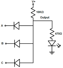
Status Monitor - I understand your comparative approach.. It's straight forward, modern and dynamic: input Buffers, processing, output drivers. I was thinking something a little more state machine-ish. There are only 8 possible combination success states to be detected. Maybe just simple diode AND gates to detect each state? Something like below.
Attachments
Images (1)

The 3-input "AND" gate you show is conceptually correct but needs assistance to work in the application at hand.
On the input side, presumably A, B, C are from the diode-matrix and the turnout LED monitor. These signals must be referenced to a common voltage for the circuit to work. I suppose you can arbitrarily declare you will tie your 12V 33 Amp DC supply common to 14V AC DZ1000 common. The opto-isolator is another way to mix power supply commons without committing to a hard-wired connection.
Additionally, if using an LED from the DZ1000 controller circuit to detect the status of a turnout, note this was a pulsed AC signal that could be a negative voltage. This polarity must be corrected. An opto-isolator is one way to perform logic inversion.
The AND gate requires well-defined input voltages to establish state. For example, a high voltage = 1, low voltage = 0. But when a diode-matrix output is off, there is effectively no voltage at all. No voltage is not the same as low-voltage; no voltage will behave as a logic 1 input to your AND circuit as drawn. For example, if input A has no voltage, it will be interpreted as logic 1 because the diode at input A will be off (the same as apply a high voltage to input A). It could be as simple as placing resistors to common at A,B,C to define the inputs as low-voltage = 0 when no signal is connected. In my example, I placed this input resistors on the output of the opto-isolator.
Re-visiting what I call "well-defined" input voltages, the "high" voltage from the diode-matrix will be about 12V DC. If tapping the LED voltage from a DZ1000 controller, the LED will be "on" with a voltage of only 2-3V DC. The AND input must interpret this arguably low-voltage (relative to the 12V from the diode-matrix) as a logic 1. In my example, I use an opto-isolator's inherent current-transfer function to implement this voltage conversion.
On the output side, if A, B, C are all high voltage = 1 since then all 3 diodes will be off, the voltage at the output pin will be high and the LED turns on. If any input A, B, C is low it will turn on the diode and the output pin will drop to near 0V and the LED turns off. As drawn, you have a 470 Ohm current-limiting resistor on the LED. That's fine for a hooking to 12V DC. But note that the output pin does not provide anywhere near 12V DC with LED on. You have a 10K resistor to the positive supply. So the LED is being driven by 12V DC via a 10.47K resistor which light the LED but quite dimly. In general, digital logic chips are designed for speed and low-power which effectively comes at the expense of large output current driving capability. Obviously there are digital chips that can drive motors, solenoids, speakers, etc. but these are specialized chips vs. what are affectionately referred to a jelly-bean logic chips (like AND gates). In my example the digital logic chip output is buffered by a transistor to provide more LED current.
Finally, on what you call the processing or the combinatorial logic function of the AND gate, if I understand your logic you only use AND gates. So if one or more turnouts are instructed to diverge (per one or more diode-matrix outputs) AND those turnouts are detected to be in the diverge position, then turn on the LED for that route. This is a necessary condition but arguably not a sufficient condition? Specifically, what if one or more of the other turnouts happens to be in the diverge position? The magnitude-comparator method compares all 8 turnout positions with all 8 turnout commands. This can devolve into a philosophical discussion of what is good enough etc.
Addendum on processing. IWhile the 8-bit digital comparator may seem like overkill, note that it too is a compromise. Specific to the application at hand, status monitor logic as proposed only tests if turnout(s) commanded to diverge are indeed diverged. And, if using a more exhaustive full 8-bit comparison, it additionally tests if turnout(s) NOT commanded to diverge are indeed NOT diverged. However, and specific to trains, there is that "annoying" behavior of switches to get stuck between points for any number of reasons. It depends on the switch-machine design but a stuck or incompletely thrown switch might have both red and green indicators on (or off) at the same time! A stuck turnout can cause a derailment whereas a turnout in the wrong position might be recoverable if watching yard operations on the video monitor. Hence this would be 8 more "inputs" to the status monitor circuit. In other words, it may not be good enough to know that a turnout is not diverged...you may also want to be sure that it is straight!

So rather than the easy-way-out of only monitoring the DZ1000's Red LED as a proxy for Diverge, you could also monitor the Green LED. 2 inputs, 4 possibilities. For each turnout, this would require a 1-input NOT gate (aka inverter) plus a 2-input AND gate. The Diverge status signal would be true only for the upper right combination... so Diverge = Red & ~Green.
Attachments
Images (1)

Stan - My AND gate diagram is just notional. The logic design is not limited to just AND gates. The idea is to use discrete's, rather than IC's. I will not be using the DZ1000 controllers, but will add resistors to provide a current path to illuminate the LEDs in the switch machine DZ1000. I'm aware of the difference of between high, low and open. Use my trusty 12 VDC 33 amp supply as power. No mixing AC neutral and DC ground.
I'm not looking for a closed loop electronic solution. The operator visually sets the rotary switch and visually verifies the route via the status board. As an example: when the operator sets the rotary switch to Lane 6, turns the toggle ON and pushes the momentary; the verification that the turnouts for Lane 6 are correctly positioned would be determined from the DZ1000 switch machine states by monitoring the I/O that normally feeds the DZ1000 controllers. The correct states are "hard wired" (i.e. programmed) into the let's say "diode" logic, so the status LED will only illuminate when the logic conditions are met. If for example, Lane 6 required three turnouts to move to complete the route, I would expect AND logic to be all "1" for example and illuminate the status LED for Lane 6 indicating that the turnouts are correctly aligned. I understand that the DZ1000 output can be either positive and negative half wave rectified pulsed DC. Maybe the optocoupler module can help in part with the interface as you suggested. 
Addendum on processing - Let's keep it simple. I'm not looking to build fault detection into this project. If it was an aircraft, that would be different. As an aside, I haven't experienced any hang ups with Ross turnouts using the DZ1000. The NJ switch machine is a different story. The NJ switch machine leaf spring contact assembly is crap. I greatly improved the situation by paralleling the contact sets.
@shorling posted:...
Maybe the optocoupler module can help in part with the interface as you suggested.
Well, yes, if by optocoupler module you mean as your included photo then sure that would provide isolation and you could use the SPDT relay output to select between, say, DC+ and DC- on the NO and NC contacts and call the relay COM as the output. This would provide a solid logic output in response to a low current DC input that could be on a different power system. And, you could stack multiple modules to implement the fundamental combinatorial logic functions (AND, OR, NOT). For example, with 3 of these modules (i.e., 3 SPDT relays) I think it's not a stretch of the imagination to sketch how to stack/daisy-chain the relay outputs so that all 3 relays must be "set" for the final output to be high...thereby creating the "AND" logic function.
OTOH, you could also use an optoisolator/optocoupler module (no relays) that I'd think would be less expensive.

No question messing with optocoupler modules requires some study to apply whereas relays are fairly easy to understand. Note how the phrase "Voltage Converter" is used in the description. As with the stacked relay method, you can also stack multiple optoisolator outputs to effect combinatorial logic functions.

In upper example, all 3 couplers must be "on" for the output to be "on." That is, all 3 output transistors are in-series so that all 3 must be on to pass current to the output. This effects the AND function.
In the middle example, the 3 output transistors are in-parallel. So any one or more of the transistors can pass current to the output. This effects the OR function.
In the lower example, swapping the inputs to ab optocoupler input logically inverts the output transistor. This effects the NOT function.
To use your terminology, this is simply notional. There are i's to dot, t's to cross to use in a real world circuit.
It seems from your more recent posts that you're really up on all this stuff! It's very difficult in a forum environment to know what are the known-knowns, known-unknowns, unknown-knowns, and unknown-unknowns (a 4 output truth table!).
Attachments
Images (2)


Stan - Thanks for Optocoupler info and how to AND, OR, etc. Looks like the Optocoupler is the just the transfer device and everything else is external ?
Here's where I am in the process:
1) Revisiting the yard track layout to arrive at a final design.
2) Complete the truth table for the final yard track design.
3) Develop strawman for Status Monitor
4) Scale the final strawman designs to the final yard track design.
5) Determine parts and cost.
5) Order the electronic parts. Defer track purchase until later this year when needed. I could pick it up from Ross at October York but not sure if I will go due to Covid.
Thanks again, you have been a great help. I'll going to be out of pocket the next couple weeks. When I return, I'm sure I'll have more questions.
@shorling posted:...
Looks like the Optocoupler is the just the transfer device and everything else is external ?
If you dissect a generic 4-terminal optocoupler, there's a 2-terminal LED aimed at a 2-terminal photo-sensitive transistor. That's all folks!

Apply current to the LED, LED turns on directing photons to the photo-sensitive transistor and the transistor then can switch current. The key parameter in an optocoupler is the CTR % (current-transfer-ratio). So if you drive the LED with, say, 1 mA...how many mA can the phototransistor carry. Typical optocouplers will be in the range of, say, 50% to 200%. More is better as it simplifies application. So to your point, it is indeed a current "transfer device" and must be surrounded by other components. On the module above, you can see other components. And perhaps the best example is the optocoupler relay module where there are many external components including the relay needed to control Amps of current. A generic optocoupler itself only handles "signal level" currents of, say, a few mA.
I like your use of the term "notional" to describe where we are. There are details and fine-print in small-font to attend to. For example, when applying AC vs. DC there are considerations.
Attachments
Images (1)
Unless speed is an issue, one option for low light levels is the Darlington opto-isolator, it typically has much higher current transfer ratios.
@gunrunnerjohn posted:Unless speed is an issue, one option for low light levels is the Darlington opto-isolator, it typically has much higher current transfer ratios.
GRJ - Thanks for your input. Good to know.
@stan2004 posted:If you dissect a generic 4-terminal optocoupler, there's a 2-terminal LED aimed at a 2-terminal photo-sensitive transistor. That's all folks!
Apply current to the LED, LED turns on directing photons to the photo-sensitive transistor and the transistor then can switch current. The key parameter in an optocoupler is the CTR % (current-transfer-ratio). So if you drive the LED with, say, 1 mA...how many mA can the phototransistor carry. Typical optocouplers will be in the range of, say, 50% to 200%. More is better as it simplifies application. So to your point, it is indeed a current "transfer device" and must be surrounded by other components. On the module above, you can see other components. And perhaps the best example is the optocoupler relay module where there are many external components including the relay needed to control Amps of current. A generic optocoupler itself only handles "signal level" currents of, say, a few mA.
I like your use of the term "notional" to describe where we are. There are details and fine-print in small-font to attend to. For example, when applying AC vs. DC there are considerations.
Yes, "notional" is where we are on design approaches for the Status Monitor. For turnout and power control, I'd say we're at preliminary design.
Thanks for the additional insight on Optocoupler application. I reworked the Yard track layout and worked up costs including the turnouts, track and wood for the tray. Pricey but it will be worth it to get more trains out of boxes on onto track.
During my working days with a subsidiary of Corning Glass,, we made a device called a PINFET whch combined an opto chip with an FET. It was widely used in fibre optics networks. I believe that many of the current opto-isolator products use this technology.
@stan2004 posted:On the input side, presumably A, B, C are from the diode-matrix and the turnout LED monitor. These signals must be referenced to a common voltage for the circuit to work. I suppose you can arbitrarily declare you will tie your 12V 33 Amp DC supply common to 14V AC DZ1000 common. The opto-isolator is another way to mix power supply commons without committing to a hard-wired connection.
Additionally, if using an LED from the DZ1000 controller circuit to detect the status of a turnout, note this was a pulsed AC signal that could be a negative voltage. This polarity must be corrected. An opto-isolator is one way to perform logic inversion.
Hi Stan004 - summer is here and I'm not doing much on the train but in my spare moments I'm building the monitor panel we discussed. It's just the panel with LED less the electronics I'm building. But, I do want to have the electronics details worked out BEFORE I complete the panel. The electronics are not going to be mounted in the panel.
I'm using the Opto Isolated Relay Modules we discussed above. My plan is to daisy chain the relay 12 VDC outputs to provide the AND logic. The VCC for the modules is 12 VDC. The monitor LED indicators are 12 VDC. The inputs to the Opto Isolator Relay Module are AC from the DZ1000 controller shown above. 14 VAC feeds the DZ1000. One of your schematics above shows using the signal across the DZ1000 controller LEDs as the module trigger. You correctly noted that the trigger signal is pulsed AC which could be negative. You also suggested that Opto Isolator could be used as a solution without connecting the AC and DC commons.
My AC and DC commons are currently separate on my layout and I want to keep it that way. I could add a small 12 VDC supply to support the monitor if necessary.
I don't actually plan on using the DZ1000 controllers. I can substitute discrete components like LEDs and resistors as shown in place of the controllers. The DZ1000 switch machine motors are the stall type, so it important to keep the quiescent current draw in the stall range.
I'm looking for guidance on the interface design between the DZ1000 Controller LED's used as triggers and the Opto Isolator Relay module trigger input. Any help would be appreciated.
I did complete fabrication of my yard status display below. OCC is yard lane occupancy and RTE verifies yard route turnout alignment to access a specific lane. My yard is not yet built but will be located in another room separate and not visible from my layout. This status display along with a remote camera hopefully will permit safe yard operation. The yard is strictly for train storage, not consist building.

Attachments
Images (1)

@shorling posted:...
I'm using the Opto Isolated Relay Modules we discussed above. My plan is to daisy chain the relay 12 VDC outputs to provide the AND logic. The VCC for the modules is 12 VDC. The monitor LED indicators are 12 VDC. The inputs to the Opto Isolator Relay Module are AC from the DZ1000 controller shown above. 14 VAC feeds the DZ1000. One of your schematics above shows using the signal across the DZ1000 controller LEDs as the module trigger. You correctly noted that the trigger signal is pulsed AC which could be negative. You also suggested that Opto Isolator could be used as a solution without connecting the AC and DC commons.
My AC and DC commons are currently separate on my layout and I want to keep it that way. I could add a small 12 VDC supply to support the monitor if necessary.
I don't actually plan on using the DZ1000 controllers. I can substitute discrete components like LEDs and resistors as shown in place of the controllers. The DZ1000 switch machine motors are the stall type, so it important to keep the quiescent current draw in the stall range.
I'm looking for guidance on the interface design between the DZ1000 Controller LED's used as triggers and the Opto Isolator Relay module trigger input. Any help would be appreciated.
As you observed earlier, the DZ1000 controller LEDs receive a pulsing (positive or negative depending on turnout position). If you use this 60 Hz pulsing voltage to drive the relay module, those modules are fast enough such that the relay contacts will buzz/chatter opening/closing 60 times per second. You could indeed daisy-chain the chattering relay contacts to implement some type of AND logic...so that, for example, two relays need to be closed to power a particular LED. So ignoring the loud chattering from the relays, the AND'd LED would appear "steady" on in the same way the DZ1000 Controller LEDs appear steady on even though driven by pulsating 60 Hz. I do not recommend this approach. Yes, you could mess with the circuit adding, say, a capacitor on the input to the relay module so the pulsing triggers smooth out.
If you use solid-state opto couplers (no relay), the outputs after isolation are still pulsing. You can still perform AND logic using various methods discussed (stacking opto outputs to implement AND, using your diode-AND gate, using AND-gate logic IC chips, etc.). The final output will be pulsing but an LED will appear steady to the eye. And, again, you could mess with the circuit with capacitors to smooth out the status voltage.
As to what I'd recommend. I'd say it depends on the complexity of the AND definitions. I'd think these would have been finalized if you've already built up a panel and such. The details get boring but basically as you have more complex AND definitions you run into loading issues with how many AND circuits a particular DZ1000 controller LED must drive.
@shorling posted:
Stan - Thanks for your thoughts, always a help. I have built the panel but not the electronics. The electronics are going to mount remotely from the panel. Regarding the turnout position status monitoring, my latest thinking is to simply use the SPDT DZ1008 relay and the above diode AND to interface between the DZ1000 and the status LEDs. The DZ1008 is not my favorite relay but no chatter and it's designed to work with the DZ1000. Seems simple and should work. I'm using a dedicated 12 VDC supply for the yard project which would tie AC and DC commons. Hopefully connecting the commons is not going to degrade the DCS or Legacy signals?
My embedded yard status panel photo didn't display in my above post so I edited the post to add the photo as an attachment.
Not familiar with dz1008 relay but being a relay, it isolates the AC turnout voltages from the relay contacts. The DC supply would be used for the AND logic using the relay contacts to feed the AND inputs. So I don't see the need to connect the AC and DC commons.
Stan - Thanks for the inputs. Thinking about again, you are correct, the AC and DC commons do not need to be tied. My brain was still in the opto isolator module mode which required commons tied for the trigger to work.
I haven't looked at the turnout and track power control schematics but as I recalled those AC and DC circuits were relay isolated. DC used for logic control and AC relay output for turnout and track power control.
@shorling posted:Track Power Alternate Configuration: One 12 VDC 33 amp supply,
I first want to appologize for being so late to comment on this. But when you consider that each switch motor draws less than 100mA, a 33 amp supply will switch 330+ switch motors simultneously. It may be a major overkill. If that is what you already have, I understand.
@Gilly@N&W posted:I first want to appologize for being so late to comment on this. But when you consider that each switch motor draws less than 100mA, a 33 amp supply will switch 330+ switch motors simultneously. It may be a major overkill. If that is what you already have, I understand.
Thanks for the input. The 12 vdc 33 amp supply has been installed on my layout for years and has quite a load on it already but I’m sure it still has lots of capacity to handle the yard DC electronic load. My AC and DC commons are currently separate and I don’t want to tie them for fear of Murphy’s Law.
It's fall, train time and I started my winter yard project. My yard is going to be located in separate room from my layout. The two rooms are separated by 10 inches of concrete foundation. This weekends project was to breech the foundation shown below.

Attachments
Images (1)

Some time has passed, it's 2024 and my yard has progressed beyond the planning stages. I have a platform with Ross switches and track which connects to my layout through my 10 inch concrete foundation. Yard control is via DCS eliminating the need for a separate Yard control panel. I built 3 logic boards and installed a video camera to observe yard train movement. The logic boards provide track power control, route switch position feedback and occupancy. When the switches are properly aligned an enable signal is sent to track power control. A single push button routes track power to just the selected yard lane. Yard Lane Route position and Occupancy are display on the LED Train Board. I'm just beginning to connect the wiring to the logic boards. and verify operation. So far so good. The yard has 9 lanes plus a bi-directional reversing loop. The yard is not intend to be proto typical, just functional storage with no scenery or hidden mechanics. There is also a wooden rolling work platform over the yard to facilitate access for construction and maintenance.
I've completed setting up DCS routes to control the yard switches which are Ross with DZ 1000. I use DZ 1008 relays to generate isolated switch position electrical signals which feed route logic to illuminate the selected Route LED when all switches are in proper position. I use this same route signal to enable yard lane track power. As a result, selected lane track power is prohibited unless the switches for the selected lane are aligned. A single momentary push button switch turns only the enabled lane track power on/off. Next up, installing yard lane track power feeds. Lastly will be lane occupancy detectors.
Add Reply
Sign In To Reply
