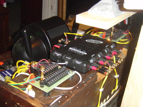
Hi all.  I have a MTH 24-Port Terminal Block connected to a MTH z4000.  I keep getting an overload when I connect the block to the accessory screws on the z4000.  My question is do to black and red wires need to be together.  For example, there are two sides and each side has 12 spots for accessories.  I'm using the block to connect all of my switches so they have direct power to each switch.  Each side has a red and a black spot for the wire.  Does the black and red wire from each item that I am connecting need to be on the same row?  Can I just put all of the black wires on the black side and all of the red wires on the red side or do they to be in the same row... so the black wire from one switch needs to be on the black side of the same row or that switch that I connect the red wire to?  


Thanks,
Dave

Original Post

Replies sorted oldest to newest

That's what I thought.  When I was stapling the wires under the plywood table, I accidentally nicked one of the wires.  I got the staple out, but that is probably messing everything up... it is going to be a long night tonight.


One other thing, I'm using Fast Track switches.  I took the jumper out and connected wires to the switch to the terminal block.  Even thought the terminal block in not working for me (as of now), when I put power to the track, the switch lights still light up... does that sound correct?  I thought by running the switches to the accessory power, they would only light if that was connected?


I appreciate all your help.

Originally Posted by DJP:

That's what I thought.  When I was stapling the wires under the plywood table, I accidentally nicked one of the wires.  I got the staple out, but that is probably messing everything up... it is going to be a long night tonight.


One other thing, I'm using Fast Track switches.  I took the jumper out and connected wires to the switch to the terminal block.  Even thought the terminal block in not working for me (as of now), when I put power to the track, the switch lights still light up... does that sound correct?  I thought by running the switches to the accessory power, they would only light if that was connected?


I appreciate all your help.

Sorry but I am not familiar with Fastrack switches but I did use a lot of Super O at one time and they would act as you expect  Do not power up off track power and only light when the separate power would be applied. 


Another suggestion I would make is not to use staples.  Run your wires in troughs or through holes drilled in the benchwork.  If you want to make it neat you can cable tie them together   Staples cause major problems  They can go through wires and short things out and are a bear to diagnose.  Mike CT has the neatest and best looking wiring I have seen in the world


IMG_0943

Attachments

Images (1)
  • IMG_0943
Last edited by bluelinec4

DJP,

   Think of it in this manner, although you have a ground and hot connection terminal

coming into the head of the 24 connection terminal block, each A & B side is it's own entity, with Ground & Hot connections.  The upper is the ground, when you bring the black wire from your TIU to the black terminal at the head of the terminal block & the lower is the hot when you bring the Red wire from the TIU to the Red connection at the head of the Terminal Block, so you have 24 different connections to run wire from, no matter what you are hooking up.  12 From the A side and 12 from the B side.  On the A side in the picture, you can see the black wires all running to the top connection points, and the Red wires running to the bottom connection points.  Think of the terminal block as a big wire splitting operation for many different track drops & accessories.

PCRR/Dave


Notice the Black and white wire feed at the very top far end of the terminal block, that is the hot and ground wire for one of the blocks on the 3rd level of our old FT layout.

The top being the ground Black wire (outside rail) and the bottom being the White/Red Hot wire (mid rail).


4th and 5th level Pine Creek Railway 002

Attachments

Images (1)
  • 4th and 5th level Pine Creek Railway 002
Last edited by Pine Creek Railroad
Like I said I didn't use these on my layout.  I thought one side was red and the other side was black.  Both levels being the same.  I used a different connector that gave me 20 ports and was 1/4 the cost. 
Originally Posted by bluelinec4:
Originally Posted by jmiller320:

I didn't use these, but I thought the red side was all connected together and the black side the same way.  I would double check with a multimeter.

Isn't that the same as all A's are red and all B's are black?  Its simple  No meter needed


Thanks again all. 


Rixster, I was told I pushing the limit with track power and switches.  Originally I was running a 4x8 table with 6 switches and a CW-80 transformer.  Some of the switches were not switching if I had too many cars attached to the engine.  SO I decided to upgrade to the z4000 as well as the layout... now it is 16 switches with (2) 4x8 tables and (1) 2 x 8 table.  Since I was upgrading they said I should use the block.  Think for what I described, I don't need the block?  Also as an FYI, I did run a bus wire.

DJP,

   If you have the older 022 or 711 type switches that draw massive power it is definitely better to power them separately from their own power transformer, however if you have the new low voltage FT type switches you can definitely use track power to

power them, eliminating all switch wires if you have either the Cab1 or Legacy Cab2

remote control that operates your FT CC switches.

PCRR/Dave

Last edited by Pine Creek Railroad

You'll have more flexibility in your wiring if you use screw eyes and wire shower curtain hangers to route your wire. Run the screw eye into the table, pop the curtain hanger open and thread it through the screw eye, instant wire hanger. Easy to add and remove wires from.


Red Z4k 14V Accy Out to Red Block Post, Black to Black. Upper screws to FT switch 'Aux In', lower to 'Aux Gnd'. Make sure to remove the track power jumper from the FT switch first. Since they only pull power when thrown, 16 FT switches shouldn't be a problem for the Z4K.


Last edited by Len2

First lets look at the terminal block. There is a red pin that connects to 24 posts (all the lower ones). A Black pin connects to all 24 upper posts. The red and black are electrically isolated.


Switches are all connected to common via the rails. One phased wire is needed to connect the accessory transformer common to the track common. Connect all the switch hots to the red side of the terminal block. Wire the red post to the accessory power hot.


The Black post can be used in several ways. Common for the accessories. Hot for accessories which would allow one to run accessories at a different voltage than the switches. The accessories can be commoned to the track.


The OP stated he is using the accessory pin of the Z-4000. This has an output of 14v at 4 amps roughly. I would test the amp draw by connecting to a throttle handle set at 14 v and checking the draw. If using the black post above for hot one can connect to the 10v pin on the Z-4000 to get another 4 amps of accessory power.

Hi again, I wound up trying the suggestions from everyone and could not get it working, so I decided to scrap powering the switches from an accessory and just use track power.  


One thing to mention, before my next problem, my track power does work, and even though I was going to use accessory power for the switches, the lamps were all on yet the terminal strip was not connected to the accessory inputs on the transformer,  was this normal?


Now, I started to disconnect the wires and let the switches run off of track power, they will not work at all... remote does not work, the lamps do not work, nothing.  I tried to create just a small layout with 2 switches and they did not work either.  Is there a reset on these switches or does it sound like I really screwed this up.


Thanks,

Dave


Now I have an even bigger problem. I cannot get any of the 16 switches to work.  

To run the switch with out track power you have to hook the switch up to an auxiliary power supply.  To do this you have to remove the jumper.  There are three slots where the jumper plugged in.  AUX GND, AUX IN and Track Jumper.  Place your black ground wire or what ever color you are using into the AUX GND slot.  Place the Red or what ever color you are using for Positive into this slot.  The jumper does not go back in.  The rails will get their power from the connecting rails.  The power for the light and switch motor will come from the auxiliary power source. 


Make sure you do not cross the wires.  Make sure you have power going to the switch rails.  There may be a piece of track with the jumper wire missing.  If you are using the switch to run a separate powered loop, make sure you remove the jumper on the piece of track with out roadbed.

Do you have the instructions that came with the switch?  Try taking one switch and hook up the power to the Aux In and a ground wire to the ground.  Make sure you remove the jumper first.  The light should come on and the switch should change directions when you move the lever.  Don't hold the lever in one direction too long.  If this works the switch should work.  Try all your switches.  What part of New Jersey are you located?  There maybe someone close that could stop in and offer you some help.


Just to give everyone an update on this.  I went to my local train store and he could not get it working either.  He wound up calling Lionel today.  I also emailed them on Friday and got a response today.  Turns out that there was a bad batch of switches that were wired wrong in production and is only affected when connected to auxiliary power.  The strange thing is the switches that were affected were from about two years ago.  Where I purchase everything, their stock moves, so I'm really surprised by this (as is my train store).  Lionel gave me and him instructions on how to re-wire each of them or I could send them back.  Well I'm sending them back, I'm not the best solderer and to do 16 of them would take a while.  I just hope I can get them back in a timely manner.  Thanks for all your suggestions.


Dave

Add Reply

Post

OGR Publishing, Inc., 1310 Eastside Centre Ct, Suite 6, Mountain Home, AR 72653
800-980-OGRR (6477)
www.ogaugerr.com

×
×
×
×
Link copied to your clipboard.
×
×