
Replies sorted oldest to newest

If you get it apart.  This is what you are looking at.  Not a real hard solder job.  It may be easier just to send them back.

Bottom cover plate off, the two big flat head screws allow for the motor to be removed.  Motor out of the way, there is one screw in the PC board.   Probably best to re-solder all three wires.  Note the Red and Green were re-soldered in the first picture, The yellow is about to fall off. Yellow also needs re-soldered.


Last edited by Mike CT

rtr, I'm guessing that a heavier wire would put more strain on the solder joint.  The #28 being used is very flexible.


I have found that on the controllers, it is easy to take them apart.  I'm installing a few dozen, and on some I have to switch the red & green LEDs.  I take them apart, and the wires joints are them readily accessible.  I find that the LEDs on the motors are easy to switch.

The problem is that the end of the wire, Red, Green, Yellow, needs to be tinned so that the solder sucks-back into the small strands inside the insulation.  The current install, the tinned wire is only the end of the small wire, so the wire easily breaks at the end of the insulation.  As always, IMO.  Mike CT  Not sure why you just can't use the wire that fell-off.   

Last edited by Mike CT

I also had the 28 ga. wires work loose from the solder points on the switch motors.  I used 22 ga. stranded copper wire, tined, and resoldered to the board.  Worked fine.  I agree, the 28 ga. wires are way to flimsy to work with.   I have numerous spare switch machines and push buttons, every time I go to York I take a bag full of defective ones, with my card inside and give to Dennis.  He repairs them and sends them back.  Be careful with the LED's - they are polarity sensitive, one side is flat, if it does not work, swap the ends.  I use a pair of straight pliers to pull them, a small needle nose simply can not grasp the led. 

I think I found an easy fix for the broken wires on the DZ 1000. A #3 metric screw self threads into the hole where the wire is soldered. I purchased some 1" screws and cut them into short set screws slotted with the dremel tool. Tin the ends ow the new wire, insert and tighten set screw. do not over tighten or you will crack the circuit board. I took one apart and had a tough time with it.

Railroad 033

Attachments

Images (3)
  • Railroad 034
  • Railroad 032
  • Railroad 033

To follow up on my earlier post, I tried a few possible remedies.


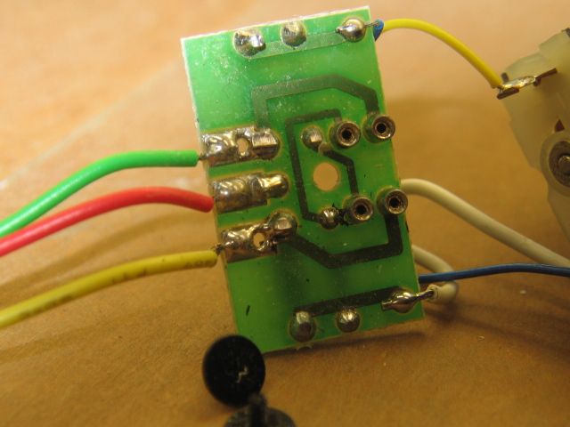
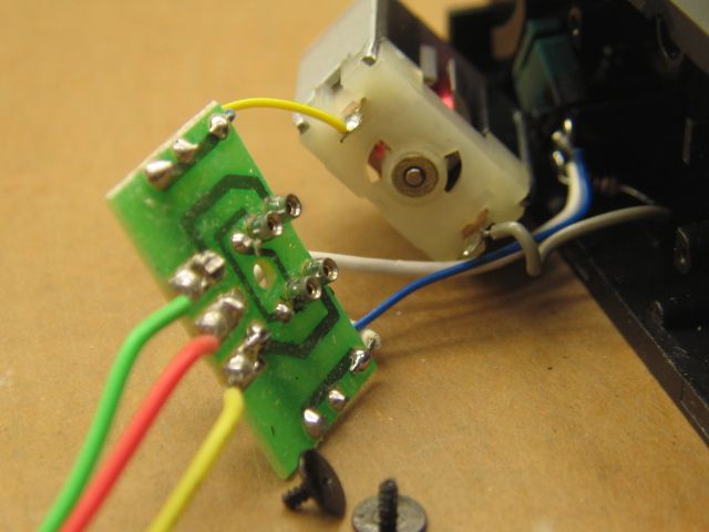
I had the same problems as others. It worked, did not work, one side worked, etc. My first effort was to test the switch machine unhooked to the turnout. I found that they all worked to various degrees. So my next step was to add a little graphite.


Next I moved the turnout without being attached to the switch machine. Some were ok but others had some drag due to the ties or rails. I lubricated the bar under the rail and scrapped away some of the wooden ties to get an unencumbered movement.


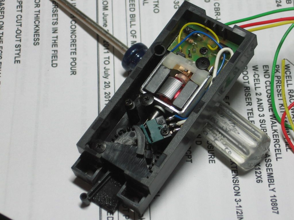
After that, I positioned the switch machine, by hand, trying to get the the optimum movement and position. Once I was satisfied, I put one screw to hold the switch machine. Some worked and others did not. I moved one machine a quarter of an inch away from the ties and another I had to put a small shim under the back end of the machine.


I have seven working so far in the yard and four over one section of the main line. Only twenty more to go.


Good luck everyone.


Add Reply

Post

OGR Publishing, Inc., 1310 Eastside Centre Ct, Suite 6, Mountain Home, AR 72653
800-980-OGRR (6477)
www.ogaugerr.com

×
×
×
×
Link copied to your clipboard.
×
×