Thanks!
Thanks!
Replies sorted oldest to newest
Shortening it a bit so the next section doesn't touch it. I've read some people do that then add a little super glue to it.
The plastic pins have the gap center filler. Hard to tell from their photo what that measurement is.
If you cut and create the gap you damage the track for possible reuse. It will work. If it arcs, you may have to trim a little more after installation and testing.
The pins are best, but you can do it either way.
Thanks Carl, 5:40 in the morning so I gave up on it for the night lol. Figure I better order those pins so hopefully they can get here soon.
Lance,
You mention the center rail, you don't do anything to the center rail. Either use the plastic pins or cut one of the outside rails. Then run a wire from the outside rail to say a gate, then connect another wire from a power source to the gate. The gate will go down when the wheels complete the electrical connection to the gate.
JohnB
JohnB,
He is isolating power divisions at a crossover. (interlocking)
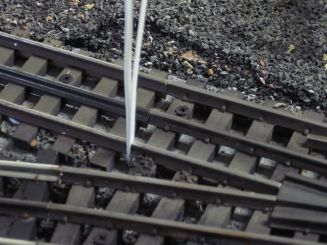
autolumination sells these insulating pins under their super O parts. These work well
Thanks Carl I missed that.
Lancer,
never mind...use plastic pins
JohnB
JohnB,
That's ok. I have been following his Layout progress. he didn't say. Nice layout.
Thanks!
These styrene strips were inserted in an existing set-up to provide an isolated activation rail. I used a dremel to cut the pin/provide a gap in the rail. Installed, they were glued in place, with CA (Cyanoacrylate), Super glue, and then trimmed to the rail contour. The isolated rail section is used for automatic non-de-rail, DZ 1000 switch motors.
Every place I have a insulating pin or rail cut in the outside rail I paint the end of the tie next to the insulating pin/cut white. I use the ends of the center rail in gargraves switches for the center insulating joint. I checked each switch for wires on the bottom side and cut wires as needed.
For DCS operation, I just cut the rail with a Dremel wherever I needed a cut and filled the gap with whatever I had that was handy. It was a while ago and I can't remember what I used.
.....
Dennis
I like the plastic strip method. I didn't know that GG even made plastic pins! But the plastic strip makes sure they don't touch better IMHO.
I use the plastic O gauge pins from Gargraves now. I used to use K-Line's S gauge plastic pins and cut them down a little on the sides to fit O gauge Gargraves track.
To keep proper alignment in the curves I have found it best to use the plastic pins rather then any other method.
While talking about Gargraves track don't forget that all three rails are separated electrically from each other.
Also Gargraves switches differ in certain years as to whether they have center rail power going all the way through the switch rails or not.
Lee Fritz
Years ago I had 2 DCS channels isolated with a lift out bridge. No insulator. Over time what was once a slight gap now had the center rails slightly touching. Didn't really notice an issue till I blew a fuse. Didn't realize one blew. Now one channel was trying to handle way to much track. My DCS signal wen't totally south. Spent a few evenings and finally saw the problem. A little more trimming and some styrene and it won't happen again.
I use a toothpick.