I didn't look, but that makes sense. That's about all the power they're going to want to dissipate, and I've never seen a uP that handled the max on every pin. ![]()
Thanks to all of you. I thought I remembered the 20mA no. from way past reading. The problem with buying things on ebay (like relays), they give you an overview with no schematics or things like 'how much current to trigger the relay'. As I found out it was only 1.2mA and the problem was bad contact in the breadboard. They are going in junk pile and a buddy recommended a better source.
Again thank you for the help as always,
Ken
@ken's trains posted:...The problem with buying things on ebay (like relays), they give you an overview with no schematics or things like 'how much current to trigger the relay'.
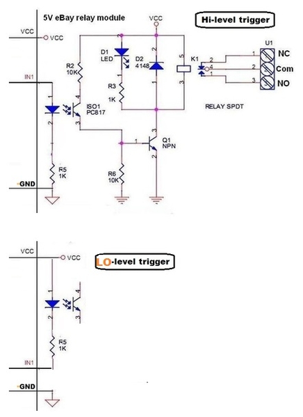
On rare occasions you'll find a schematic included in an eBay listing. Earlier in the thread I showed the following for the 5V relay module that I got from an eBay listing. Many modules allow you to choose either HI or LO triggering. The selection (usually via a push-on jumper) is effectively as shown below:
So you're basically just driving a optocoupler LED thru a resistor. Your ~1 mA measurement seems about right.
When you previously suggested needing 80 mA to "trigger" the relay(s), I concluded you meant you were also driving the relay coils themselves with the poor Arduino output pin. In which case you would do as you suggested - a simple NPN like the 2N3904 used earlier could provide enough current gain.
Attachments
Thank you Stan. I did remember your earlier post with the relay schematic. The new relays are 4-ch--not previously bought. I believe the listing did say opto-coupled, so I also assumed low current to trigger. When they didn't, I blamed it on the listing--not my junk breadboard (which was the cause).
Thanks as always,
Ken
P.S. This work is for a fully automated draw bridge which was also 3D printed. When I get the SW worked out, I will post a video on youtube with a link here to see turntable & bridge operate.
OK, now for a real problem. As I think I explained, I'm trying to automate the control of a drawbridge. I have 2 Arduinos and 2 sets of 2 channel relays to apply/remove power to isolated track sections. The bridge side Arduino, receives UP & DOWN cmds. from the other Arduino in response to train detection via a set of 4 sensors (2 on each side--I have an inside & outside loop crossing a single track bridge}.
I found some ground insulated tracks and decided to use them as sensors. Train on one of the 4 sensor tracks, bridge comes down, power is applied to isolated sections & bridge to allow train to cross, detect train passing opposite side track sensor, and raise bridge when clear. Simple when just rolling cars to test. Then used train (post-war engine) to test. Worked couple times, then went crazy. Changed Arduino on 'controller' side 'cause it was damaged. Tried another and when I ran train, damaged 2nd Arduino. Concluded that since all of my electronics is tied to AC ground and the sensor input from the isolated tracks is a ground, there must be much noise on ground.
So replaced ground isolated tracks with IR detectors across tracks in 4 places. I only connected inner loop sensors for test purposes and modified program to take into account. The electronics for the sensors provides a HIGH when beam unbroken and LOW when broken. Again when tested with just rolling cars, worked as programmed. When I used an engine under power, it worked a couple of times, but then would not follow the program. It seems as though noise is causing the program to jump around. However, I have not damaged the Arduinos with this setup, but electrical noise seems to be the problem.
First thought is to modify the sensor electronics to provide a HIGH when not broken & LOW when broken (might be more noise resistant). If that doesn't work, might try a separate DC power supply and run a separate DC-only ground bus. If that doesn't work, might try shielding all the control lines that run between the 2 Arduinos.
Please, please, any thoughts or suggestions would be very much appreciated. I am at my wits end and almost ready to give up on automating this function--although when it works, it's pretty neat to watch.
Again, my program works just fine until I start running engines on the tracks.
Ken: If you could sketch out your wiring diagram, take a photo, and post it here, that would be helpful. Also you could attach your Arduino code. Are you debouncing the track sensors?
Leo, the only reason I didn't provide a sketch is that my original connection was very simple. Input from ground-isolated track to Arduino input terminal which is held HIGH via a 10K resistor. Train wheels complete ground to Arduino. But this process shorted out input terminals when I ran train. And as to de-bouncing in my code, no I didn't think necessary due to simplicity of circuit.
I will make a sketch of my proposed IR sensor circuit and include the Arduino program I am using. My question on the circuit however, is it better to just provide a LOW from the sensor output and hold the Arduino HIGH with pullup resistor or can I put the pullup resistor in the sensor circuit (on the transistor output side--I know this will require a diagram; give me an hour).
Leo and Stan,
Here is my approach to providing IR sensor inputs to my Arduino controller. My question is where is it best to have the pullup resistor to hold the input HIGH. The top circuit is my modification of Stan's circuit where I added a 10K resistor to hold the output HIGH till beam is broken (I'm not sure if that will work). The bottom circuit is Stan's circuit unchanged with the Arduino input held HIGH with a pullup resistor and the sensor output providing a ground when beam is broken.
I have also included my controller program with one change not yet done; the code was for a HIGH output when the beam was broken, and it only includes processing the 2 sensors on the inside loop (one on each side of the bridge). There is no de-bounce, and just assume that when I change the sensor circuits (per groups recommendations), I will modify the code accordingly.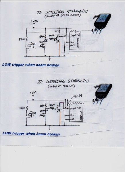
Attachments
@ken's trains posted:Leo and Stan,
Here is my approach to providing IR sensor inputs to my Arduino controller. My question is where is it best to have the pullup resistor to hold the input HIGH. The top circuit is my modification of Stan's circuit where I added a 10K resistor to hold the output HIGH till beam is broken (I'm not sure if that will work). The bottom circuit is Stan's circuit unchanged with the Arduino input held HIGH with a pullup resistor and the sensor output providing a ground when beam is broken.
I have also included my controller program with one change not yet done; the code was for a HIGH output when the beam was broken, and it only includes processing the 2 sensors on the inside loop (one on each side of the bridge). There is no de-bounce, and just assume that when I change the sensor circuits (per groups recommendations), I will modify the code accordingly.
Schematic #1 has the collector always grounded. Otherwise both schematics are identical.
I agree that there are basically the same. The difference is in the physical location of the pullup resistors. In #1 the pullup is in the sensor circuit which is located on the bridge side 10' and 25' away from the 'controller' Arduino input. This has that wire providing 5V till the beam is broken--lots of chance for AC coupling into input wire. In #2 pullup is at the Arduino and only command from the sensor circuit is a ground.
Ken: Thanks for the updates. While I peruse your Arduino code, I would just like to point out that the input pins have built-in pull-up resistors that you can enable with the "pinMode" command. The format is:
pinMode(pinNumber, INPUT_PULLUP);
There is no corresponding ability for a pull-down resistor internally.
This becomes useful for dealing with open switches or push buttons where the input is otherwise left floating because it is not connected to anything. Grounding the input overcomes the pull-up resistor and the program will see a high to low transition. Using an external pull-up resistor will do the same thing but I just wanted to be sure you knew about the internal ones.
I will do my best to review your code and let you know what I think. On first inspection, it looks pretty good. Also, I am aware that certain sections have been commented out; not unusual at this stage of development.
Leo, I used that in several cases originally, but thought it was the cause of my problems since the LOWs & HIGHs weren't as good as with physical resistors. So went back to physical.
Quick update: Changed the sensor circuits to provide a LOW when beam broken and used pullup resistors at the Arduino sensor inputs. Changed the code and tested with just rolling stock and then with train. Everything worked great with rolling stock. When engine was used, bridge came down w/o breaking beam and other strange things occurred.
I'm going with assumption that there is noise on AC/DC ground bus. So I will try phase 3 which is to use a dedicated DC power supply and connect all bridge electronics, limit sw's, and sensors to that power supply (Vcc & Gnd).
If that doesn't work, I would need a scope to see if there is emi coupled into the sensor & control lines. Then would have to find a way to shield.
Ken: The Arduino code looks alright but is a little hard to follow. I would recommend breaking the main loop into more sub-functions so that it reads more like a book. You can name the functions whatever you want so that it has a higher level of abstraction. For example:
if (noTrain(innerSensor1, innerSensor2)) {
sendUpMessage();
}
. . .
boolean noTrain (int sensor1, int sensor2) {
int status1 = readSensor(sensor1);
int status2 = readSensor(sensor2);
if (status1 == LOW && status2 == LOW) {
return true;
}
return false;
}
By isolating the different functions, you make them more readable and they can take care of the messy business at the low end of the operations. And by passing parameters (sensor1, sensor2), you make your functions reusable:
if (noTrain(outerSensor1, outerSensor2)) . . .
The other thing that you might want to do is use "digitalRead" rather than "analogRead" on the sensor inputs. You don't need to know the values of the analog inputs. You just need to know if they are triggered or not. The HIGH and LOW values will give you that.
int readSensor (int sensor) {
return digitalRead(sensor);
}
I know that the above function looks too simple. But consider that you may want to add a debouncing algorithm to your code. You could do that here without disruption to any of the code that uses it.
Lastly, I can not be sure that the logic of your program is correct as it is difficult to tell from a distance. But at this point, I think I would be doing more reduced testing with the engines running. I would lock the bridge in the down position and test that the sensors behave properly. Small incremental steps will get you to the final outcome. Good luck!
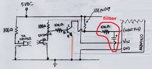
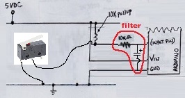
Try adding a resistor-capacitor noise filter at the Arduino input pin(s). You have 10K resistors so something like 1uF or 10uF for the capacitor. If the capacitor has polarity note the + side. Note the - side of cap should connect to GND right at the Arduino. Internal Arduino input pullup must be disabled.
Before doing this, I'd be curious if there is a particular sensor out of the 4 that is the problem. Apparently you get false triggers when running a train that is not even close to the bridge. I'd think it a simple experiment to disconnect 1 or more sensors.
Attachments
Thank you Leo & Stan,
Here is my update: I used a 12VDC walwart as a new power source and ran a separate ground from that power source to everything in the bridge circuits. Again everything worked great with rolling stock. It even worked ok for several runs with the engine. Then of all things, the train passed a sensor, the bridge started down (as it should), stopped 1/2 way, and the relays triggered (which would have allowed the train to hit a 1/2 down bridge). Apparently, the DOWN limit SW was triggered and the bridge controller sent a bridge-is-down signal to the main controller. So even the limit SW's have noise on the ground lines. I realized that I used the INPUT_PULLUP on 4 inputs lines at the bridge controller Arduino. I will go back to physical resistors on those inputs. Also, I am using AnalogRead so that I can set the LOW to the smallest possible threshold and still detect a real LOW. As to my code, I am a total novice; bought a book a year ago and had some help from a friend. Just started using functions recently.
Stan, your comment on the cap's had a "for" between 1uf and 10uf. Did you mean "or". And as to filtering, I was thinking that if the noise is constant and at a level that emulates a LOW, there is no way to filter it without filtering out the real LOW--unless I know the noise frequency--but I don't have a scope. Also, as to sensors, I only have 2 installed at this time (one on each side of the bridge on the inner loop) so as to simplify my trouble shooting. Since I put physical resistors back in the inputs, the sensors seem better, but I will check once all inputs have resistors.
Just my latest updates and thoughts. I will make some changes including pullup resistors on all inputs and reduce the LOW threshold to a level just above what I am reading for a ground input.
Thanks again for help.
Ken: The following function will return true if the specified sensor is above the 500 value threshold after 3 readings taken 10 milliseconds apart. Otherwise, false is returned. You can play with the number of readings and the delay time between readings or the threshold value (I did it your way) to see what happens. This is a basic debounce routine.
boolean sensorTriggered (int sensor) {
for (int i = 0; i < 3; i++) {
int value = analogRead(sensor);
if (value < 500) {
return false;
}
delay(10);
}
return true;
}
@ken's trains posted:..Stan, your comment on the cap's had a "for" between 1uf and 10uf. Did you mean "or". And as to filtering, I was thinking that if the noise is constant and at a level that emulates a LOW, there is no way to filter it without filtering out the real LOW--unless I know the noise frequency--but I don't have a scope.
...
Yes, I meant 1 uF or 10 uF - updated in post. It is highly unlikely the noise is "constant" or a steady DC-like voltage. To wit, if it is the running of engines that is inducing the noise into the ground rail, then the engines are being powered by an AC source which is of course NOT a steady load. I believe the noise is manifested as short spikes of voltage coupled into the wires going to the Arduino input pins. Hence I suggest an electronic filter positioned right at the Arduino inputs.
Note that the 10-cent electronic filter can also be used for your limit-switch inputs which I assume is something like:
And by extension, this filter method might have solved your initial configuration of insulated outer-rail triggering. That is, when an axle rolls over the trigger section it is essentially behaving like a limit switch in that it connects the Arduino input pin to "ground" whether noisy or quiet.
By all means experiment/explore the software method too. A contemporaneous analogy might be to think of the electronic filter as a mask to prevent the noise from entering the Arduino in the first place. The software filter is akin to a vaccine or therapy that prevents or cures the noise from any ill effects. ![]()
Attachments
Thank you very much Leo & Stan. I have just re-installed 10K resistors in all inputs to the bridge controller Arduino. I am going to test that configuration first and, if still noise problems, will try physical filters and then SW filters. Will let you know what works and what doesn't. And Stan, by the way, with the GND-isolated tracks, I was triggering things well before crossing the track.
@ken's trains posted:...
And Stan, by the way, with the GND-isolated tracks, I was triggering things well before crossing the track.
Understood. But as I understand it, while the limit switches are falsely triggering when nowhere near the limit, at least these false triggers are not destroying the Arduino. Apparently you bricked (rendered useless) two Arduinos with the GND-isolated track method. While not worth sacrificing additional Arduinos to test this hypothesis, I believe the destruction occurred when the train was over the GND-isolated sections when there was a direct physical connection (i.e. a galvanic connection) from GND to the Arduino input pin. Again, do not try this at home, but I believe a physical filter would have prevented this; this would be an example where the software method would be ineffective.
@stan2004 posted:
By all means experiment/explore the software method too. A contemporaneous analogy might be to think of the electronic filter as a mask to prevent the noise from entering the Arduino in the first place. The software filter is akin to a vaccine or therapy that prevents or cures the noise from any ill effects.
I'm all for filtering noise from an input signal. That's a good recommendation.
But switches bounce as the contacts are imperfect. If adding more electronics eliminates the bounce, and makes it easier to program, that's a bonus.
The way his program is using the sensor inputs, they have to be perfect or his sequence will fail. I don't think that getting more than 1 reading is all that difficult and serves to confirm what is really happening on the layout.
It's called software because it's supposed to be easier to change than hardware.
Thank you both (very much). I will now confess to my poor troubleshooting. Back whenI put in an isolated DC supply, I ran the rolling stock test with the AC off. After putting in all physical resistors and using the analog inputs, I also connected my DC supply to the system AC power strip. So this time when testing, I had AC on (didn't do that before except when running train). Ran the rolling stock test and it was a mess. I have a manual UP/DWN toggle sw. I toggled it DWN and it came down part way and stopped (limit SW was triggered)--happened almost every time. So, the problem is not just the trains running, but having some AC circuits powered.
Since I would have to completely re-do my circuit boards to put filters in all the inputs, I will first try SW 'debounce'.
Thanks again for all your help. I am going to take the rest of the w/e off and hang myself, or, will report later.
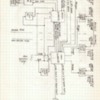
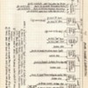
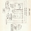
Just to add a little clarity as to what I'm dealing with, I have enclosed some block diagrams and a pic of one of the 2 controllers (the Bridge Controller).
Attachments
Always forget something.
When doing my testing, forgot that I had the switch track constant voltage pin power on. That meant switch track on either side of the bridge was powered. The 2 inputs/outputs shown on the update are switching controls. They operate solenoids to move the switch to one position or the other and are wired to operate in sync, so when one switches to inner loop position, it triggers the other to move to the same position. Thought this might be issue since those 2 lines are in same bundle as Bridge control status lines running across floor under Bridge span. Sooo, re-ran the test with switch power OFF. Bridge operated fine with no AC powered. Then just turned on the main power bus (transformers & DC power supplies ON, but no power to tracks or switches. The Bridge operation immediately got messed up.
Attachments
And for Leo. I apologize if asking too much from the forum, and please tell me to stop if that is case. But, in looking at your de-bounce routine, I realized I've never written a function that passed data. Mine were "void's"; did some stuff and went back to main program.Started to read about functions but brain hurt. So my question is: Can a general de-bounce function be written that will work for every input to be tested or does a separate one need to be written for each input to be tested (e.g., one for inner sensor1, one for outer sensor1, etc.)? In other words can you just pass the function whatever input value you are testing and then just return a T or F--so just one function instead of 10 or more similar functions.
@ken's trains posted:And for Leo. I apologize if asking too much from the forum, and please tell me to stop if that is case. But, in looking at your de-bounce routine, I realized I've never written a function that passed data. Mine were "void's"; did some stuff and went back to main program.Started to read about functions but brain hurt. So my question is: Can a general de-bounce function be written that will work for every input to be tested or does a separate one need to be written for each input to be tested (e.g., one for inner sensor1, one for outer sensor1, etc.)? In other words can you just pass the function whatever input value you are testing and then just return a T or F--so just one function instead of 10 or more similar functions.
Yes. The debounce function that I posted above will do that. To use it, you just tell it which sensor you want to read:
if (sensorTriggered(innerSensor1)) { . . .
Thank you Leo. Now I just need to learn how to properly implement it in my main program. i will do some reading in my Arduino programming book.
Well sorry for delay in updates, but I have been circling my you-know-what to chase down this problem. Finally received a scope from Banggood. I found the input lines to be very noisy. The setup was with the large DC supply and system/track ground to power the bridge circuits.
I took the simple approach and installed shielded cable on all input lines to arduinos. That dramatically reduced noise. I then applied a debounce function with analogReads and a low threshold (about 500mV for a LOW) to all of the inputs. Things worked ok until I ran a train. Then the program would jump to the wrong places if the trains ran too fast. I then powered the bridge circuits with a separate DC supply, using its' ground. Everything worked good 'most' of the time. What didn't make sense was, why only 'most', since the input lines looked pretty clean.
So I redid the program replacing the analogRead with digitalRead and simplified the debounce routines. This seemed to be bullet proof. So one more try with the large DC supply and system ground. Still worked good. But just as a final check, I ran an engine back and forth at high speeds without crossing a sensor--and of course the bridge went down as though I had broken a beam. Sooo back to the separate DC (walwart) supply. Ran the same test many times and no sensors were triggered.
I can only guess that at high speeds, the wheels bounce causing sparking and generates noise on the ground bus which affects the arduino inputs that are looking for a LOW (even though they are held HIGH with 10K resistors). With a ground that is separated from track ground, that does not seem to be happening.
All of this was just with the inner loop sensors installed. I am going to install the outer loop sensors and update the program to accomodate. Will see what happens next.
I guess noisy AC does not work well with ardinos.
Ken: When you're comfortable with posting your code again, please do so. I will review it and check out what you've done. It sounds to me like you are very close. Good work!
Hi Leo,
Added sensors on the outer loop, updated code, and ran train on each loop. Train on inner loop crossed sensor, bridge went down. At same time I ran train past outer loop sensor and it stopped waiting for power to be restored. With bridge down, inner loop power restored, train crossed bridge, and went past 2nd inner loop sensor. Then power was restored to outer loop, train crossed bridge, went past 2nd outer loop sensor, and bridge went up.
I was about to go downstairs for a celebratory beer, but decided to back trains up to initial points to make quick video. As I ran each train back, the program skipped a beat for each train crossing--noise, noise, noise; but why now??
At this point, I am kind of lost. Today I will do some more testing to try and isolate the problem. First thought is that the wires from the emitters/sensors to the control electronics are long and unshielded. I have 16 (8 sets of IR detectors) of those wires and they are about 18" long running past AC wires.
Ken


