
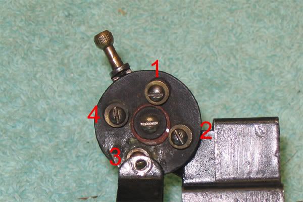
Can someone please help. I've searched the web and can't find anything to substantiate if this switch and lever are correct? Circa 1924. If it's not correct what should I be looking for??? It just seems odd to have two holes for the lever?

John

#153 reverse switch

Attachments

Images (1)
  • #153 reverse switch
Original Post

Replies sorted oldest to newest

Agree Ron, didn't have much luck with Olsen's either. Still haven't figured out the Lionel part number for the reverse unit- hopefully will never need it. Spring loaded ball bearings on one plate that make contact on other plate depending on position.  Basically a 150 humpback motor with second generation 152 brushes/holder and screw on the reverse unit and ya got a #153. Lionel knew how to market items in the day.

Just bought this piece and wanted to make sure it was authentic because of the above. Am no 100% guru but all indicators say I paid a fair price since the motor was serviced in a professional manner, having done a couple myself, it's easy to wrap up $ in parts. Probably the last one of the 150 series I'll tackle.

JHS

Thanks Joe,  the photo is great. Shows the switch from a different angle. But as Tin points out, the lever for a #153 worked differently is what I gather.

I did a mock up photo, by no means complete but might help others, as I get Tin's point. In this case, the lever needs to pass through the cab hole and is pulled or pushed in. JHS#153 reverse control mock up

Attachments

Images (1)
  • #153 reverse control mock up

I have (2) 153 locomotives.  The first two pictures show one of the 153's with the original reversing switch, original rod and screw on knob. 

The other two pictures show the other 153 with a prewar reversing switch that I modified to work.  I made the operating rod out of #12 copper wire and the knob is a round brass screw off of a light fixture which I soldered to the rod..  It works fine but some day I hope to find the correct switch, rod and knob.

Jim Lawson

Attachments

Images (4)
  • 001
  • 002
  • 006
  • 007

Great photos Jim, thanks!  One thing I notice on the original level is the bent angle of the rod,  supposed to stop it inside the cab...? Which makes sense.

On your modified version is interesting as it would seem to coincide with the photo Joe sent? Carefully bend the tab to accept your handmade lever..is what I gather.

Once I get a lever rod fab'd will be sure to post photos.

John


Thanks to all for the help so far. Photos are my attempt to fab a lever similar to original. Homegrown approach but ran through the paces and works fine. I didn't have a 4-40 NC die to run threads but the brass nut cuts it own on copper wire pretty well. Also found that a one gallon paint can handle is the right dia. but without being able to cut threads opted out. Would suggest making the copper lever first, use it for a template for final steel lever as bends/lengths can be touchy. Not perfect but might help some folks get started in the right direction.  The main drawback on the lever, and see no way around it no matter what linkage, is it protrudes in reverse mode. Several runs with cars attached, worked fine, but it looks odd. Probably why Lionel ditched this version...

Feel free to critique.  Johnlinkage on 153#153 reverse linkage drawing153 in reverse mode

Attachments

Images (3)
  • linkage on 153
  • #153 reverse linkage drawing
  • 153 in reverse mode

Add Reply

Post

OGR Publishing, Inc., 1310 Eastside Centre Ct, Suite 6, Mountain Home, AR 72653
800-980-OGRR (6477)
www.ogaugerr.com

×
×
×
×
Link copied to your clipboard.
×
×