Originally Posted by bbsfdl60:
John,
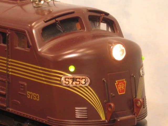
GGG told me that the board would need to be flashed with code for the board. THis engine has no marker lights just the molded spots where they should be. I might be overthinking this upgrade. I might just need to abandon the marker light idea.
Bill, To be clear I thought you were talking about MTH models that have Bi-Directional LEDs. Those that do, use a flash code to control them.
If your just talking about adding bi-dir to an engine, John's method can work, though you have an issue of only one direction light on at a time.
So I think what you are going to do is let the FWD light control return for the front LED Green side and the Rear LED Red side, while the REV light controls the Rear Green and FWD Red.
Your just going to have a lot of wires crossing the shell. Not sure why you just don't add the Green and Red like the production. G