Non-Contact Turnout Points Detector


Brief Description:

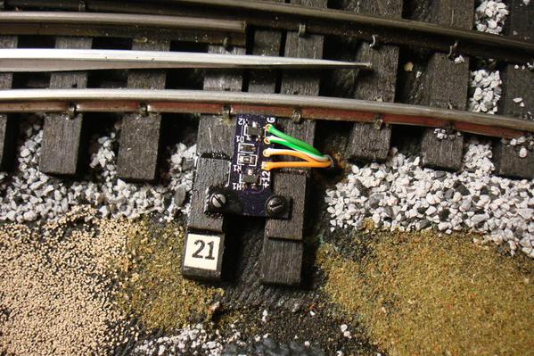
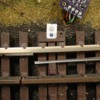
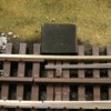
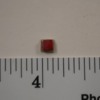
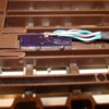
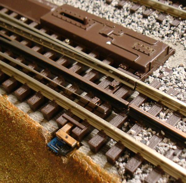
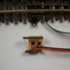
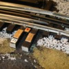
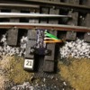
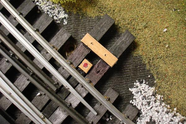
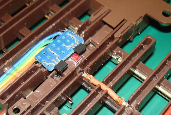
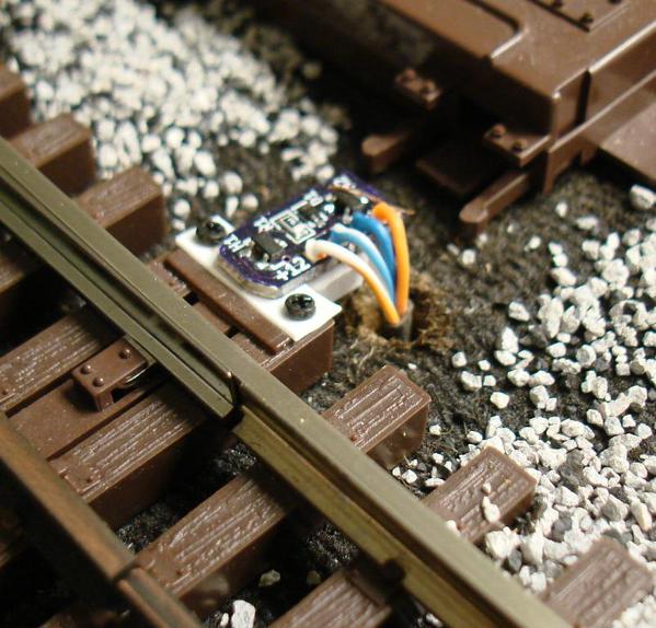
The detectors consist of a small magnet (Ø0.125” or 0.125” square) mounted on the throw bar, and a pair of hall-effect sensors mounted on the turnout ties, in close proximity to the magnet. The detectors (hall-effect sensors) do not come in contact with the magnet, throw bar, points, or any of the moving parts of the turnout, so they do not add any load.  The detectors do not rely and are in no way connected to the circuitry that operates the turnout machine. Instead, they sense the true and actual position of the throw bar, and hence, of the points.


I was going to wait a couple more months before posting this, but several questions have come up that are related to my subject.


As some of you know, I followed my provisional patent application of 2013 with a non-provisional application early this year, and I am waiting for it to be granted. A letter I received a few months ago indicated that the patent may be granted as soon as November 2014.


I have installed about 20 of the detectors already, both on single turnouts as well as on crossover turnout pairs, they work as intended, and are simply great. I have some of the annunciators (LED’s) mounted adjacent to the turnouts, and others (single, bicolor LED’s) mounted on the control panel.


At the prices I believe model railroaders would be willing to pay for the detectors, there wouldn’t be enough profit to justify the resources and effort required for me to advertise, sell, and provide adequate customer service. Therefore, I will offer what I have to anyone interested, and I will just cover my costs. I will be glad to consider providing any additional work, such as adding wire leads to the detectors, making the magnet holders, and providing LED’s and LED holders, at minimal cost.


Earlier this year I ordered pilot production runs of three models, and will be ordering more in a month or so. I will also order pilot production runs of the two ‘under’ models, and the RCS crossover model, as I described later.


My Non-Contact Turnout TRUE Position Detectors are available for the Atlas and RCS turnouts, and these are the various models.


Currently Available (in a few months):


• V5B Standard Atlas. Detector to be mounted on top of an Atlas turnout. Drives one turnout direction annunciator consisting of two LED’s (one green and one red) or a single, common anode bicolor (red-green) LED


• XVR Crossover Atlas. Detector to be mounted on top of one of the two Atlas turnouts in crossover arrangement, to be used together with a V5B on the other turnout. The V5B-XVR pair allows a single annunciator (two LED’s or single bicolor LED) to be used to indicate the direction of both turnouts in a crossover arrangement. If the points of either turnout are not fully thrown in the proper direction, the annunciator will be off.


• R5B Standard RCS. Same as the V5B but for RCS turnouts.


Coming Soon:


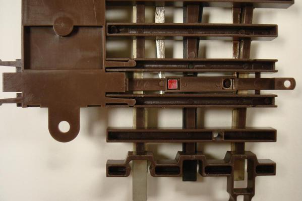
V5B-U Under Atlas. Same as the V5B, but to be mounted underneath an Atlas turnout.


• XVR-U Crossover Under Atlas. Same as the XVR, but to be mounted underneath an Atlas turnout.


• RXVR Crossover RCS. Same as the XVR but for RCS turnouts.


Note on the soon-to-be-available Under Mounted detectors, V5B-U and XVR-U.

Although these are the easiest to install and will be totally hidden when installed, since the detector and magnet are under the turnout, access to the magnet and detector may be more difficult later on.


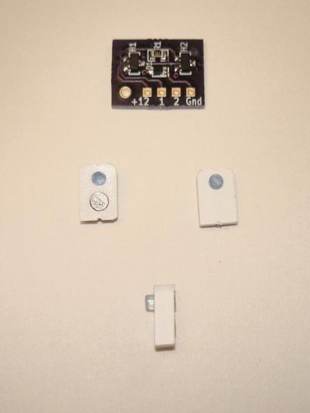
The Detectors:


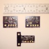
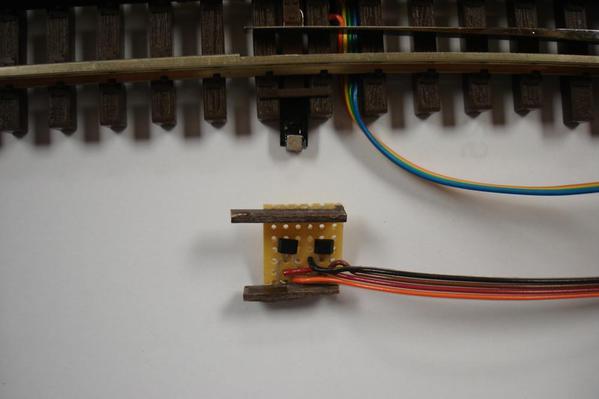
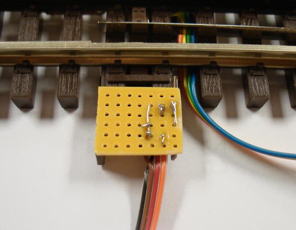
Detectors01 sm DSC08333


Magnet holder for Atlas V5B 


MagHldr01 sm DSC08338


Atlas V5B (or XVR) Installation

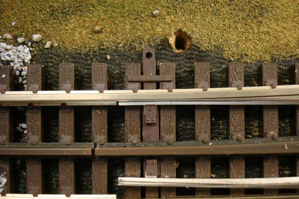
  1. Drill hole for wires

AtlSt01 sm DSC08307


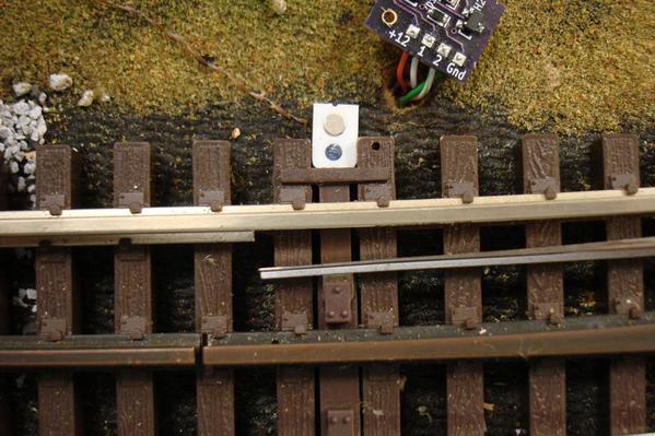
Mount magnet holder (easy snap on, add little adhesive)

AtlSt02 sm DSC08311


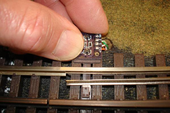
Hold detector in place to spot screw hole location

AtlSt03 sm DSC08313


Drill Ø3/64" hole for #0 x 1/4" screw 

AtlSt04 sm DSC08315


Secure detector with screw - Done!

AtlSt05 sm DSC08316


May add simple cover to hide detector

AtlSt06 sm DSC08320


RCS R5B Installation

Glue wood spacers on ties and magnet (on small wood carrier) on throw bar 

DSC08087


Secure detector in place with two screws - Done!

RCS02 sm DSC08092


Atlas V5B-U (or XVR-U) Installation

Magnet and spacer

 U00 sm DSC07951


Glue magnet with wood spacer in throw bar recess (a perfect fit!)

U01 sm DSC07978


Hold and mark detector location (to match magnet location)

U02 sm DSC07968


Press detector in place and add a little adhesive - Done!

U03 sm DSC07975


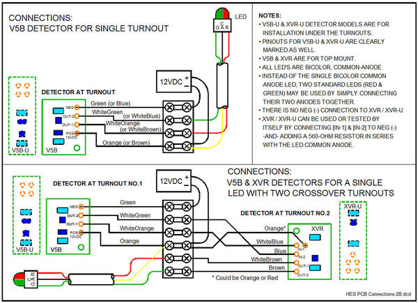
Now the detector(s) have to be wired. Here is how:


Wiring Diagram


HES PCB CONNECTIONS-2S


Thank you for reading this far!

If you have any questions, please don't hesitate to post them or to email me.


Alex

Attachments

Images (15)
  • Detectors01 sm DSC08333
  • MagHldr01 sm DSC08338
  • AtlSt01 sm DSC08307
  • AtlSt02 sm DSC08311
  • AtlSt03 sm DSC08313
  • AtlSt04 sm DSC08315
  • AtlSt05 sm DSC08316
  • AtlSt06 sm DSC08320
  • DSC08087
  • RCS02 sm DSC08092
  • U00 sm DSC07951
  • U01 sm DSC07978
  • U02 sm DSC07968
  • U03 sm DSC07975
  • HES PCB CONNECTIONS-2S
Last edited by Ingeniero No1
Original Post

Replies sorted oldest to newest

I had a couple of emails from forum members suggesting that this thread be over on the for sale/ trade forum.  Just a little history to help let others who don't know...Alex developed these detection devices initially for his layout.  As he shared his turnout problems and the development of how he was going to solve those problems with this idea he had, others expressed that they would be interested in having something like this installed on their turnouts since they had the same concerns as Alex.  To make a long story short, Alex wanted to make these available to a broad audience to help others since he had not planned on physically producing the detectors himself.  The patent process he has gone through at this point is to protect his "invention" and perhaps someday this can develop into more than what it is now.  My point being...Alex is not a business and not competing with anyone else.  He has no website or order center and is only making these available currently because he has shared the process here on the forum and forum members expressed their interest in purchasing these.  At the time when Alex actually has some to sell to forum members, he will post the appropriate thread in the for sale/trade forum.  I want to point out that this is a prime example of one of the advantages of being a member of the forum where other members make available knowledge and even sometimes products from which you as a forum member directly benefit.  Alex has been particularly generous in this regard as have many others!   Thanks Alex for bringing this ingenious detector to the membership!!
 

Alan

Paul,


According to the Atlas website, item number 0057 is an Illuminated Switch Control Box. It is a switch that controls a turnout, and it includes green and red lights or LED’s. 


However, if something such as a piece of ballast, rolling stock, or other electrical or mechanical malfunction prevents the points from throwing in the desired direction, the 0057’s green or red LED will still light up EVEN if the points did not throw properly.


My Non-Contact Detector, on the other hand, DOES NOT control the turnout; instead, it simply very accurately detects the true position of the throw bar and points, and its associated LED will indicate thus.


Not only will my detector indicate the true position of the points, but it will also detect a 0.020" or smaller gap between one point and the stock rail, and neither of the LED’s will light up at all. With my system, Green indicates fully thrown normal, Red indicates fully thrown reverse, and if both LED's are off, it means that the points are not fully thrown.


Therefore, not only will my non-contact detector help you prevent a train from going in the wrong direction, but will also help prevent derailments at the turnout.


Thank you for your interest!


Alan (OGR Ad Man) is 100% correct – I could not have said it better!

It is not feasible for me to try to make any money with this. If a company, such as Atlas or RCS were interested, they could, indeed.


When I determine how much it actually costs me to procure the detector PCB’s, how much it costs me to make the magnet holders for the Atlas top mount detectors, and perhaps the cost of procuring the various styles of LED’s, I will post a thread in the "For Sale" section of this forum, with the prices.


However, to be able to offer the detector PCB’s, I need to know if there is any interest so I can order a quantity of said PCB’s beyond what I need myself. If there is no interest, I will order just enough for my layout.


Thank You Alan for your post.


Alex
 

Two other advantages of my Non-Contact Detector system (*).


One. Since it is not connected or in any way linked to the ‘switch machine’, it is perfectly suited to be added to manually operated turnouts. It will detect and indicate the direction of the turnouts with LED's at the turnout locations, or at the control panel.


Two. If for any reason, anyone such as a visitor or an operator, manually throws, purposely or mistakenly, a remotely operated turnout, the Non-Contact Detector will detect that event, and the LED’s will indicate so accordingly.


(*) The ‘system’ is comprised of the detector PCB, the LED or LED’s, the 12VDC supply, and wiring.


Alex
Last edited by Ingeniero No1

Alex, Thanks for the quick reply and answer to my question. Now I am really interested in them. A few more questions if I may. I see that it is powered by a 12V battery system. I have a MTH Z4000 that has a 10V and 14V accessory hook-up. Would either of these work? Correct me if I am wrong, each switch would have a magnet, detector and a green/red LEDs. Where would the LEDs be located and how are they attached? You showed a cover for the detector, is that supplied also or are they scratch-built by owner? Have you thought about mounting the LEDs on a vertical pole to make it look like a real switch throw?

Here is a short video of the Non-Contact Detector in operation. Note that as soon as the throw bar starts to move away from its 'home' position, whether normal or reverse, the LED that was lit will go off.


'Non intended consequences': The LED's reflect on the Atlas switch machine and make it appear as though it has lights - it does not.


Let me know if I can answer any questions.


Thanks for watching!


Alex
Last edited by Ingeniero No1

This detector is unbelievable in action. Alex's video is great, as they always are, but to see this detector work in person is unbelievable. I visited Alex one weekend and he showed me this idea he had....Alex's smile was from ear to ear. He is quite the guy when it comes to electronics. Most of what I saw that first day, I did not understand. About 6 months later we went back to see his additions to his wonderful layout and he had some of these detectors working on his layout, they were flawless. I really wish that some of the guys that produce switches would take the time to look at this and add this little detector to their switches. It sure would make our hobby a little easier for some of us and would also be worth the $$$$. As they say, In My Humble Opinion.

Last edited by Roger Wasson

I like how close it monitors the switch position, we occasionally have an Atlas switch slightly open and that derails the next thing coming down the line.  Since the switch should always be one way or the other, another really neat feature would be a monitor that would tell you if the switch was in never-never land for more than a fraction of a second.  Imagine if the panel beeped to tell you a switch was not totally closed? 


Roger wrote:

"I really wish that some of the guys that produce switches would take the time to look at this and add this little detector to their switches. It sure would make our hobby a little easier for some of us and would also be worth the $$$$. As they say, In My Humble Opinion."


I couldn't agree more. It would cost the switch-track OEM very little (probably around a dollar) to add this feature to their products. Some say that their controls already do what my non-contact detector does, but that is just not so. My detector monitors the actual position of the throw bar and points.


John wrote:

"I like how close it monitors the switch position, we occasionally have an Atlas switch slightly open and that derails the next thing coming down the line.  Since the switch should always be one way or the other, another really neat feature would be a monitor that would tell you if the switch was in never-never land for more than a fraction of a second.  Imagine if the panel beeped to tell you a switch was not totally closed?"


Yes, a beeper  definitely would be nice, John, and it could easily be added and operated by the signal, or lack thereof, from the detector. What I do now is look to see if any of the indicators (LED’s) are not on (red or green), which would mean that something is not right. I tried illuminating both the red and the green to indicate a wrong-position, but that did not work well – it looked sort of like orange. BTW, I designed, built and tested some 20 different methods and versions before I reached the current design, which of course, ended up being the simplest.


And thank you Spence!


Alex

Last edited by Ingeniero No1

I am thinking it would be possible to have LED's at the switch and at the control panel, operated from the same detector board? I think that would be a good way to have them on my layout. I like the 2 LED setup just as you have in your video, for both panel and at the switch. Have to think about the single LED at the panel idea for a while, but that might be a good idea also. I also like the covers you have at the switch machines and would like to have those on my switches also.


Anyway, I am interested and will need at least 12 and probably end up needing 20 or so by the time all my switches are installed and layout is complete. I definitely would like to get at least 12 for now though, when ever you have them available. I think you have a great idea here. I am also using Atlas switches with Atlas switch machines.

It should be easy to create a buffer to add remote indicators.  Probably in most cases, the cost effective solution is to have a multi-LED buffer board to minimize the cost per switch.  The alarm I previously mentioned could also be a multi-indicator sensor.


The only reason I suggested the alarm is that if you have a busy panel with lots of indicators, noticing one that's not lit is not that obvious.  The absence of an indicator is not nearly as obvious as one that is perhaps blinking or an audio alert.


Alex, you'd done the hard part with the really neat sensor technology, I think you have a great product here!


Thanks Alex, I will be watching for more info. I'm not in a any big hurry, plenty left to do on the layout. Atlas won't have any more switches until late this year and I'm still a couple short for what I'm doing right now.  I like gunrunnerjohn's idea of an alarm also, along with the added LED's. Not sure what the buffer board would consist of, but I like the idea. That would definitely wake someone up if they were asleep at the switch so to speak.    You guys are going to end up as a model railroad electronics device manufacturing company. (Edit: I should add stan2004 to the new company also.)

Last edited by rtr12
Originally Posted by Ingeniero No1:

Roger wrote:

"I really wish that some of the guys that produce switches would take the time to look at this and add this little detector to their switches. It sure would make our hobby a little easier for some of us and would also be worth the $$$$. As they say, In My Humble Opinion."


I couldn't agree more. It would cost the switch-track OEM very little (probably around a dollar) to add this feature to their products. Some say that their controls already do what my non-contact detector does, but that is just not so. My detector monitors the actual position of the throw bar and points.


Alex wrote......BTW, I designed, built and tested some 20 different methods and versions before I reached the current design, which of course, ended up being the simplest.


Elegantly simple, the epitome of good design.  Pat B.

Originally Posted by Ingeniero No1:

Alex,


And thank you for suggesting it! Making a video had not crossed my mind, and your suggestion was all the motivation I needed.


If a picture is worth a 1000 words, how many pictures worth is a video?


Thx!!!!!!


Alex

The video was great Alex, it points out details that were not apparent in the stills or the descriptions.

Pat,

Yes - another example of the KISS principle. In this case, a rather involved initial approach, or approaches, evolved into the simplest solution.


John -

I agree. Since I am familiar with the operation of the detector, I was 'filling in the blanks' subconsciously with the missing details. What was obvious to me is not so obvious unless you see the system in operation.


Thank you both!


More Background - The 'Why'

One key element I failed to mention was the reason why I developed the true-points-position detector in the first place. Yes, the detector had to be non-contact because anything that comes in contact with any part of the turnout could potentially impede its operation, but why the need?


The main driving force behind my effort was computer control of the trains. I lucked out with my 100%-computer controlled HO layout (1988-1993) in that I never had a malfunction of any the Atlas turnouts. I could detect if a train was incorrectly routed, but that was only after the train was detected at the wrong track. But how to prevent a train from being routed incorrectly?


The design I finally settled on (the simplest) can not only provide the signals to illuminate the LED’s, but said signal can also be easily used by computer train control software to check whether the turnout command signals have thrown the points as desired, and done so fully. The software can also poll the appropriate turnouts ahead of a train in motion to insure that the route has remained as intended.


Alex


Last edited by Ingeniero No1

John wrote,

One question occurs to me.  How tricky is it to get the board and magnet exactly aligned so that you get the great performance you see in the video?  Specifically, I'm talking about sensing the switch is not fully thrown. I'm curious whether you can get that level of indication easily on every switch installation.


John, the desired degree of accuracy was part of the development. The distance the magnet travels, of course, is fixed by the throwbar travel. Fortunately, this distance is the same or very close for both Ross and Atlas. That left two variables to determine: the distance between the sensors, and the distance between the sensors and the magnet.


I played around with this for over a year and made many samples. I started with sensors right next to each other, until I had them too far apart to provide two signals. The distance I selected provides the level of accuracy you see.


The distance between the magnet and the sensors is not as critical because of the strength of the tiny neodymium magnet and the high sensitivity of that Hall-effect sensor. By the way, I tried many different types and brands of sensors.


Once I had the electronic design finished, the most difficult part was the attachment of the magnet to the throwbar, and of the sensor to the turnout ties. Again, after many trials, I came up with what I posted. The PCB rests on the two ties on either side of the throw bar, located by the small bar that is on top of these ties, and one screw holds it in place.


The magnet holder I make is located in place by the small hole in the Atlas throwbar, and it installs easily. The distance from that little hole in the throwbar and the magnet is critical, but I worked it out and is now fixed. The small hole in the throwbar is were the small peg on the magnet holder fits.


If the system is too sensitive, a small shim, say 0.02 between the PCB and the ties normally solves the problem, but I have not had to use it yet. I know it works because I tried it and it does decrease the sensitivity somewhat; i.e., the gap between the points and stock rail can be made wider.


This having being said, it is totally feasible to install the magnet any place on the throwbar and the detector PCB anywhere close to it, to suit individual requirements. Just take a look at a few of the many configurations I tried, all of which I tweaked, got them to work, and still are on my layout!


HES Early Version 1 med DSC06660

HES Early Version 2 med DSC06693

HES Early Version 3 med DSC07086

HES Early Version 4 med DSC07484

HES Early Version 5 med DSC07482

HES Early Version 6 med DSC07892

HES Early Version 7 med DSC08397


RTR

I made my own, it is a long story, but I’ll try to make it brief. For my senior design project at Purdue many years ago, I designed and built from scratch, at the component level,  a computer or programmable controller to run a train, and I programmed in its native machine language, Alex1. Back then I used reed switches and rather unsightly magnets glued under each car to keep track of the trains, and it worked fine. (Outstanding Senior Design Project of the Year at Purdue.)


Fast forward to 1988, when I built something similar but using a brand spanking new $3000 Compaq computer with a screaming 8086 running at 8MHz, 640KB of memory, dual 360KB 5-1/4 diskettes, and a whopping 10MB hard disc drive.  I wrote the control program in QuickBasic and assembly language. The system worked like a charm. I demonstrated it over 100 times and it never malfunctioned. I have a video of it, but it is in VHS.


I kept track of the trains with train location detectors, which were 48 Hall Effect sensors installed between the ties at strategic locations. I attached a small round Alnico (*) magnet on the bottom of each car and locomotive, and the number of cars and engines on each train was entered in the program, together with their ‘home’ locations. This system allowed me to keep track of each train consist, and even uncouple and couple cars with the Kadee couplers and their permanent magnet uncoupler. It was a joy to see in operation.


(*) Neodymium, actually NeFeB, magnets were just being developed and were way too expensive. Now, the much smaller and cheaper Neodymium magnets can be used for this.


Sorry for the long post . . .


Alex

Attachments

Images (7)
  • HES Early Version 1 med DSC06660
  • HES Early Version 2 med DSC06693
  • HES Early Version 3 med DSC07086
  • HES Early Version 4 med DSC07484
  • HES Early Version 5 med DSC07482
  • HES Early Version 6 med DSC07892
  • HES Early Version 7 med DSC08397
Originally Posted by SantaFeFan:

Nice, 


We are testing our LCS module that reads switch position information from Fastrack and Atlas non-derail boards.  Connect with us if you wish to determine if your design is useable with LCS, I think folks who use Atlas track would be happy with a solution that combines the technologies.


Hi Jon,


Thank you! I Just sent you an email.


Alex

Thanks Alex, I appreciate the detailed info and enjoyed the long post. Thanks for taking the time to post it. Sounds like a neat system. I have read a little about the JMRI software for folks managing their railroads. I think some are doing similar things with that. Sounds like something I would really like to try someday, but might be a bit too complex, and I have so many things planned already...


I started with my first computer slightly before you got your Compaq maybe 1986-87. Got a Xerox (same as AT&T's made by Olivetti). It was 8086 and I think it only had 256 or 512 kb memory and dual 5.25 floppies. I added a full height, 10 meg hard drive a year or so later. It took up 2 full 5.25 bays and weighed a ton.  I also used to program in Basic, Quick Basic and Microsoft Basic 7.  I still have Microsoft Basic 7, although it's probably no longer useable with the newer Windows versions. Assembly language was always above my level, but I did have an add on library for Basic 7 from Crescent software that was written in assembly. Think I still have that also. Then Windows took off with Visual Basic and C++, I fell behind, never to catch up. Ah, the good old days when computers were fun! 

Thanks Alex. Great thread and you provide a lot of useful information. This looks like a great product that solves a problem I am having at my train club now. I am definitely interested in some sensors for my club. We use Ross switches. The Ross switch does not have the crossbar that the Atlas switch does near the movable bar. Will this make it hard to align?

RTR12 -

Those were the days . . .

My Compaq was quite an improvement over the Pet, Apple-II, Radio Shack TRS80, Sinclair, Kaypro and others I had at home and at work. It is hard to believe that back in the Pet days (when you had to make your own cables), we thought it was great to be able to write a program that was 8KB long, and that it could be stored on audio tape in as little as 30 minutes time!


Pat,

The Ross switches are rather easy to do.What I have done that works best is to make a small magnet holder out of 1/16" x 1/4" wood strip, make an Ø1/8" hole for the magnet, and glue it on the throwbar. Then use the same strip to make small spacers for the detector PCB, align it (easy to do), and screw it down.


Like this: 


RCS01 sm DSC08087

RCS02 sm DSC08092


It does take a different detector PCB, but the cost will be the same. I'll order some of those as well.


Thx!


Alex

Attachments

Images (2)
  • RCS01 sm DSC08087
  • RCS02 sm DSC08092
Last edited by Ingeniero No1

Alex,


Just saw your reply to RTR12 so count me in as well. I really like my Ross switches, but this will take the points all the way to both sides and provide an additional level of assurance.


As several people said, the video helped a lot and your pictures above for Ross sealed it!


I'm in. Great product and can't wait to place an order!  Terry

Update:

I have a better approach to install the detector on the Ross turnouts and have the instructions for their installation about complete. I finished the instructions for the Atlas (four pages, 12 figures) and I am in the proof-reading phase right now. When done shortly, I will email the instructions to those who have expressed an interest. 


This is how the Ross will be installed now [until the next improvement, that is  ]


HES-RCS 04 med DSC08421

HES-RCS 06 med DSC08422


Back soon . . . 


Alex


PS. Thank you to those who have emailed me.

Attachments

Images (2)
  • HES-RCS 04 med DSC08421
  • HES-RCS 06 med DSC08422

A little setback, but nothing serious.


In my interest to make the turnout points True-Position, Non-Contact Detector as easy to install as possible, I tried to limit the current supplied by the detector to the LED’s within the detector circuitry. Unfortunately, this created a condition that can cause the red LED to turn on very dimly and very briefly when the green LED turns on.


Even though this aberrant, brief condition could be ignored, I don’t like it and I have a fix for it. To keep the cost of the detector still as slow as possible, however, the installation will now require that a resistor be added externally to the LED’s.


Whether a single bi-color (green-red) Common Anode LED is used, or two individual (green and red) LED’s are used, only one resistor will be required. The resistor, R1, will be connected in series with the anode lead of the Common Anode bi-color LED, or in series with the two appropriate leads of the individual LED’s – as shown below.


LED Connections


I have contacted my PCB manufacturer and have asked him to quote the change. I should have an answer shortly.


I had finished the installation instructions for both the Atlas and the RCS turnouts, and in the process of checking my own instructions, I found this obstacle. As soon as I have the new detector layout, which may well remain the same, I will update the instructions if necessary, and send them to those of you who have asked for them.


Thank you,


Alex

Attachments

Images (1)
  • LED Connections
Last edited by Ingeniero No1

Add Reply

Post

OGR Publishing, Inc., 1310 Eastside Centre Ct, Suite 6, Mountain Home, AR 72653
800-980-OGRR (6477)
www.ogaugerr.com

×
×
×
×
Link copied to your clipboard.
×
×