I want to improve the slow speed performance of this engine. If anyone has added ERR to this model, I would appreciate some advice. I am a first timer on adding ERR. Many thanks.
Attachments
Images (1)
Original Post


|
|
Replies sorted oldest to newest
I have this #505 K Line and run it in TMCC mode and am generally pleased with the slow speed performance, and performance at all speeds. I assume yours has TMCC? I run Legacy system, but run this engine in the TMCC mode.
Gun Runner may be your best help but will tell you that you will need to do a tether between the engine and the tender as that's where all your electronics will go ( in the tender. )
I bought a beautiful blue Lionel FE F3 diesel set (ABA) from a follow TCA member last year. It was made in the 1990's and was conventional with one powered A unit and railsounds II in the B unit.
I gave the set to my friend and follow forum member Dan LaPage (eingineerdan@yahoo.com). Dan installed TMCC in the A unit and built a tether to connect to the railsounds board in the B unit.
Dan either now has or is getting his Lionel Service Tech certificate. He is setting up to perform these conversions. You could contact him for advice / pricing if you like.
Joe
I believe Gunrunner John said that he did put a Cruise M in a 505 but had to tip the motor drive board over backwards somewhat and elongate the screw holes on the heatsink to get the boiler shell back on. I had tried it with the board vertical, the shell lacked about 1/8 inch of coming all the way down in the back. It looked slightly off horizontal when looking at the engine from the side. Another issue inside the engine was that the Cruse M board had parts in the way for a bundle of wires to rest as they did with the stock motor driver. I decided that I did not like it and instead bought the PRR 060 from Lionel which had just come out in Legacy for climbing hills. I put the K-Line back to stock TMCC...it's still a beautiful engine anyway.
It will be slightly more challanging for a first timer since most Cruise M installs just involve removing 4 screws from the power devices and swaping out the boards. In the B6 I elongated the 4 holes in the heat sink at an angle so the board could be tilted towards the top of the backhead. After that everything fit.
Remove the motor driver and place the Cruise M in the heat sink while mounted in the engine. Tilt the board as far as it will go to get an idea how much the holes need to be egged out.
Its worth the effort. The engine runs like a watch now.
Pete
Yep, the install in several small locomotives required modifying the mount as Pete describes. It's not that difficult, but it is a bit of mechanical fitting. I put them in some Camelbacks and I had to actually move connectors on the motherboard, what a PITA. ![]()
Thanks for all the replies. I have to think about this for a while. Fortunately, I have several other model projects to work on and this is not a critical need, just a pipe dream. I will keep all your comments in mind.
I recently renewed my research on this project and wondered if I could do it. I also contacted a local tech to see if he would do it if I chickened out. Well now that I am thinking about pulling the trigger on this project, I found out the ERR cruise commender M for steamers is not in stock. Fortunately, the loco does its job well enough, but I was really wanting to try it. BTW, because the R2LC is in the tender, I would need a separate connection between the engine and tender to connect the blue wire from the new board. I will check on line to see if Lional dealers have any in stock. Thanks for all your replies.
Do you have pictures of the innards of the tender and locomotive? Is the DCDR in the locomotive or in the tender? Other than upgrades, I haven't run across a factory installation with the R2LC in the tender...
I see the R2LC in the engine ![]()
CJACK: I sent photos to Ken at ERR and he said the R2LC was in the tender? I don't have the loco apart right now. When you removed the old board on your engine, did you see where you could remove the heat sink from the loco chasis to elongate the screw holes so the new board could be tilted backward.
Chuck, is correct. This is a standard B6 and the R2LC is in the engine. Its the board sitting horizontal over the motherboard. The DCDR motor driver is behind it sitting vertical. When replacing it with a Cruise M the holes in the heat sink will have to be ovaled at a slight angle so it fits top tilting towards the cab.
Pete
The boards in the engine is indeed the R2LC and the DCDR. I'm a bit surprised that Ken would say it was in the tender.
Hey thanks Pete. So that eliminates the need for another connection between the loco and tender. I have been reading your previous post over and over to get an idea of how you did it. Did you remove the heat sink from the chasis to elongate the holes? How severe of an elongation was it? If the new board is 1/8th of an inch longer so it sits 1/8th higher, then I I could give it a try myself. If I can find a CC-M.
Thanks John.
You just have to hold the board in there and tilt it until it'll fit, then figure out how to enlarge the holes. Depending on how close to the existing holes you are, you can either elongate the holes or drill new ones. I had to do some serious fitting to get the CC-M into the K-Line A-5, probably even a bit smaller than the B6. ![]()
Like John says, fit the new board in, tilt it, and estimate how much you have to lengthen the holes. After you estimate but before filing its probably better to remove the heat sink to keep the metal filings out of the engine. The idea of tilting it is to prevent the longer board from hitting the top of the boiler so it won't sit higher.
Pete
Thanks Pete. I was thinking along those lines. And using a file is good idea.
I had luck finding an ERR cruise command M today. Just ordered it. I think from all the posts and watching a youtube installation of the module on a different loco that I will give it a try. The only issue might be identifying the correct point on the R2LC board to solder the blue wire but I think I can do it. It's been a while since I soldered anything, but I will study up on that before I tackle the project.
It's easy to find the place for the serial data wire. I recommend you don't solder it to the R2LC, but rather to the R2LC socket. You can either solder to the base of the male header pin or on the back side of the motherboard. Below is the ID for the pins. The green arrow points to pin-1 of the R2LC, the red arrow points to pin-24 of the R2LC. Pin-1 of the R2LC has a square pad, all the other pins have round pads. You want to connect to the connector pin noted by the red arrow, pin-24.
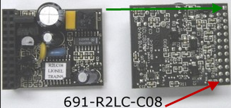

Print out this image for your records.

Pete
Thanks John and Pete. The CCM shipped today. I'll report my progress and any problems that come up.
The CCM arrived today. I started disassembling after dinner. Alignment of the unit was more than a challenge. It was 4 hours of on and off with the boiler shell. No matter how I oriented the board, the cab end was always about a 16th to an eigth high. Finally, I decided to cut groves on both sides of the heat sink so the board would sit lower. I also filed of 1/16th of an inch off the lower corners of the board sink connector flaps for clearance. That was my trick. Once the shell seated several times, I traced the location of the holes on the sink and drilled holes for the screws. I'm done for tonight since I don't yet have a soldering iron to connect the blue wire to the 24 pin. Tomorrow I may tackle that. I sure hope it works! In any case, thanks again for all your advice.
Pictures?
Well, we did tell you it would take a little doing. ![]() I recall hacking a couple of heatsinks to install these, but I don't recall the exact models.
I recall hacking a couple of heatsinks to install these, but I don't recall the exact models.
Pennsynut, did you get your K LIne B6 ERR conversion finished. How did it turn out and did it improve slow speed running?
I have one and have considered doing this (or having it done).
Access to this requires an OGR Forum Supporting Membership


