For those in the know this is a stupid question, please bear with me. I read on some site a single bridge rectifier can be used to drive multiple relays. I have used one with success and would like to add another signal to the track adjacent to the one currently in use. I understand how to link the MTH signal to the relay and how the common rail activates the coil, what I do not understand is how to power the coil on the additional relay using the same bridge rectifier. Can I just connect the (+) lead to the new relay and connect the isolated rail to the other side? The reason for the question is it will save me a bit of crawling around under the table and I have lost the local radio shack, parts are a bit harder to come by.
Replies sorted oldest to newest
Yes. It sounds like your diode bridge is a dc source of power in general, and can be used for any additional load up to its maximum current (amps).
How is the bridge rectifier hooked up right now (can you post a diagram)?
What is the (presumably AC) power source for the relay circuit?
If I understand your situation, the different isolated-rail sections must switch the "-" DC to the corresponding relays. When experimenting with a bridge-rectifier and relay for accessory activation, one typically starts out switching the "-" or common AC via the wheel axles to the isolated-rail section. Different animals. Hence my questions.
Fair question, not in a position to draw a diagram right now. Currently I have a bridge rectifier powered by the 14V fixed voltage terminal on the transformer. One leg is connected to the hot 14V terminal, the other leg is connected to an isolated rail. That connection powers the coil to change the signal from green to red when the block is occupied. The rectifier legs are all attached to a four (4) terminal block. The signal draws power from the same 14V terminal on the transformer but what I think really matters is the power connection to the coil. I think I can simply connect the (+) from the rectifier to the additional relay. Can I then connect the isolated rail directly to the new relay or does that also need to run through the rectifier. By my way of thinking that then will activate all relays connected in that group.
On my layout I use hundreds of relays powered by a Lionel 180 W brick. I run it to a bridge rectifier with a 4700 uf capacitor across the + and -. This gives me a filtered 24VDC output. The + of the bridge goes to all the relay coils. The minus shares a common with all the track transformers. (U on a ZW). The train wheels connect an outside insulated rail and completes the DC circuit to the 24VDC relay coils and timer modules. See this link if interested.
Dale H
Dale, thanks for chiming in, I was hoping you would. I have been on that link and remain stumped (dense?) What I am stuck on is this, where does the outside insulated rail connect to the relay? At the coil connection or to the rectifier? Looking at the very last diagram in your link the GREEN wire from the trolley transformer is labeled TRACK OUTER RAIL. Is that the outer rail for the track or insulated rail?
Fair question, not in a position to draw a diagram right now. Currently I have a bridge rectifier powered by the 14V fixed voltage terminal on the transformer. One leg is connected to the hot 14V terminal, the other leg is connected to an isolated rail. That connection powers the coil to change the signal from green to red when the block is occupied. The rectifier legs are all attached to a four (4) terminal block. The signal draws power from the same 14V terminal on the transformer but what I think really matters is the power connection to the coil. I think I can simply connect the (+) from the rectifier to the additional relay. Can I then connect the isolated rail directly to the new relay or does that also need to run through the rectifier. By my way of thinking that then will activate all relays connected in that group.
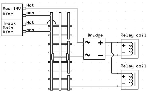
If I understand your description, your hookup is as follows and you're asking if the 2nd relay (lower one in the diagram below) will work to control a 2nd relay.
For the original (upper) relay, note that the wheel axles is passing the AC "com" when the train is present. That switched "com" goes thru the bridge to drive the DC relay coil. In the added (lower) relay circuit, the switched "com" does NOT go thru the bridge so the lower relay coil does not receive the benefit of the bridge. So it is a different configuration and will behave differently (for example the relay will probably just chatter or buzz).
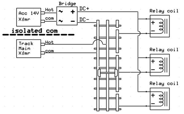
To elaborate on my earlier point, rather than switching AC "com" you can switch DC "-". This is illustrated below.
By moving the bridge rectifier before the isolated-rail sections, the wheel-axles now act to switch or pass DC "-" rather than AC "com". However, as the diagram clearly notes, the Accessory AC output and the Main AC track output can no longer share the same AC "com". Many train transformers with accessory outputs internally tie/share the AC "com" outputs. So to use this method, you need an isolated or separate AC transformer to generate the DC supply for the relay circuits. Alternatively, a DC-output wall wart can also serve as a source of isolated DC and would eliminate the bridge rectifier.
Dale's link has more details.
Attachments
To generate the red signal you would connect the insulated rail to the normally open contact. The normally closed contact would give you the green signal...
Marty
Dale, thanks for chiming in, I was hoping you would. I have been on that link and remain stumped (dense?) What I am stuck on is this, where does the outside insulated rail connect to the relay? At the coil connection or to the rectifier? Looking at the very last diagram in your link the GREEN wire from the trolley transformer is labeled TRACK OUTER RAIL. Is that the outer rail for the track or insulated rail?
Here is the diagram in question. Click to enlarge. All we are concerned with here is the coil circuit. The contacts I think reversed polarity on something like a trolley.
Note the relay transformer goes to a bridge rectifier. Not shown across the + and - you could put a capacitor. That will give filtered DC and boost voltage 41 percent,so 18 VAC becomes about 24VDC. That is a good voltage for the timers I use.
The + of the bridge goes to one lead of each of the 3 relay coils. It could be 3 or 300,whatever you need as long as you have enough transformer wattage. I use 24VDC coils so I have a 24 volt system. It powers every relay and timer on my layout.
The - of the bridge as shown goes to the ground or common of the track transformer. The common also goes to the outer rail of every loop of the layout.
An insulated outside rail can be made for each relay with 2 plastic pins. That insulated section wire goes to the other lead each relay coil. The insulated section should be long enough for at least a couple of cars to sit on. The metal train wheels connect the outside insulated rail to the ground rail that is already connected to the U. That completes the circuit and powers the relay coil. The relay stays on until the wheels leave the section and its respective capacitor discharges. Small value capacitors keep the relay from chattering when a train just enters the block. Large value capacitors can be used to create a delay off situation. Relay contacts do the switching required. Note this circuit is independent of the track center rail circuit and will even work when the train is not powered.
Note with this arrangement insulated rails can be combined,that is wired together and still kept separated electrically speaking with diodes. Suppose you had a triple crossing and wanted to activate a crossing gate or flasher. This can be done using only 1 relay,with a diode in series to each insulated rail. If on one of the 3 loops you wanted to also activate a block signal,specific for only that loop you can just add a relay for that insulated rail and switch the desired accessory and not effect the triple crossing. Current does not flow through opposing diodes. Say you want a trolley to stop in 4 places on a loop,the insulated outside rails can be wired together using a single relay.
You can also do direction logic. Here is a bi directional crossing gate for example. It also shows the relays powered with the DC- as the common.
Relays are so much cheaper and more flexible to use that IR detectors. Once you wire a few and see how it works, the get a lot easier to wire.
If when laying track you divide the outside rail up into small sections and run all the insulated outside rail wires to a barrier strip,you can now or later activate any track side accessory,easily by just adding the relay. Unused outside rails can be connected to common. Suppose you divide a loop into 12 sections for example like on the hour markings of a clock. If you want a flasher to operate on both sections 6 and 7,you can do it easily by using that wire and hooking it to a relay. If you want a train to stop on block 4,you can do that. You can make is it stop every time or every other time or make a random circuit where you can set the probability of it stopping. If only one train is run on a loop,you do not need an insulated center rail to do this. If section 2 is uphill,you can boost the voltage (conventional). If section 9 and 10 are downhill,you can reduce the voltage.
A starter set type transformer can power a lot of relays on an average layout. My layout is large so I use a 180W brick. Even 200 relays all activated at once is not a problem. My relays provide a complete train throttle.
To answer your question about the diagram,the green wire goes to common,the track outer rail that is not insulated. The other leads of the relay coil are connected to an outside insulated section. #22 wire is fine. COLOR code your wire or you will go insane.
Dale H
Attachments
Thanks all for the responses. What was bothering me was if I used the same power source for multiple relays each time the isolated rail closed the circuit for one relay all would be activated when in face I only wanted one to operate. What I desire in my particular instance is to operate two MTH 3 color block signals on 2 separate side by side tracks using 2 separate relays. I already have on working with a micro relay (your diagrams came in very handy for that particular install) and just want to power the other relay with the same bridge rectifier. Dale, I agree they are much easier to use and each one installed makes more sense.


