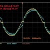
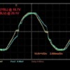
On 20 January I started a thread under the MTH DCS and PS2/PS3 forum regarding the use of a ZW-L transformer. I now have gathered additional information, as suggested by Chuck and John, which may be useful to others who do not necessarily run DCS, so I decided to post this thread here. I hope this is OK.


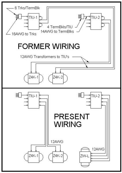
A couple of days ago I ran some tests while the DCS TIU’s were connected to the track, and with all the transformers set at 18 to 20 volts. I measured the voltage with several multimeters, and selected the one that read the closest to the transformer meters. These traces are toward the bottom of the images.


Today I ran tests on just the transformers. I used one of my two Z4000’s and the ZW-L without connecting them to the track. The multimeter I used is a Craftsman 82141, and the oscilloscope is a Rigol DS1052E.


For each test, I set the transformers so their output read the same on the multimeter, and then saved the scope trace. I noted the multimeter reading as well as what the transformer voltmeters read, and also the markings on the ZW-L handle.


NOTES:

• I could not get the Z4000 to provide voltage under 10volts as indicated by its voltmeter or as read by the multimeter.

• The four outputs of the ZW-L read the same on the multimeter when raised to the maximum. I used output A, the right-most handle of the ZW-L.

• Except at the vary low voltages, the peak voltage level of the ZW-L was around 26-27V throughout, but the 'duty cycle' varied.


(Please, click on the fotos to see actual waveform shapes)


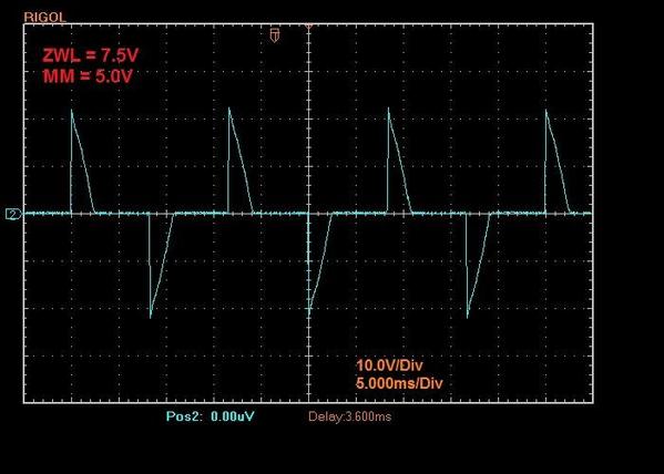
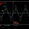
ZW-L set at 5V per the multimeter. 

The ZW-L voltmeter read about 7.5V and the handle almost at the 8V mark.

P0213-1 ZWL Alone - 5V Lbl


Both transformers set at 10V

The ZW-L voltmeter reading is noted as M12.5V and the handle position as H10.5V (Peak is about 26V)

The Z4000 voltnmeter read the same as the multimeter in every case. (Peak voltage at 14.1V as would be expected = 10 x SqRt of 2)

P0213-2 ZWL - Z4K Alone 10V Lbl


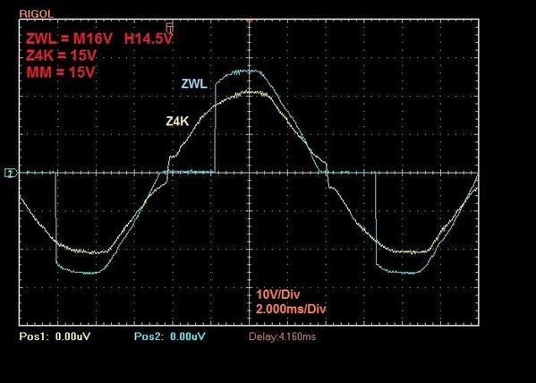
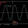
Transformers set at 15V per the multimeter

ZWL peak is about 26V and Z4K is 21 (again, = 15 x SqRt of 2)

P0213-3 ZWL - Z4K Alone 15V-1 Lbl


Same voltage setting (15V) but different time scale

P0213-4 ZWL - Z4K Alone 15V-2 Lbl


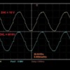
Transformers set at 19V per the multimeter

Now both peaks are close to 27V (= 19 x SqRt of 2)

P0213-5 ZWL - Z4K Alone 19V-1 Lbl


Same voltage setting (19V) but different time scale

NOTE: The Time Scale is 2.000ms/Div and not 5.000 (my mistake when noting it!)

P0213-6 ZWL - Z4K Alone 19V-2 Lbl

Above time scale should be 2.000ms/Div


Same voltage setting (19V) but different voltage scale and separate displays

P0213-7 ZWL - Z4K Alone 19V-3 Lbl


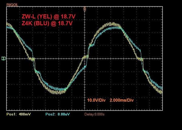
Transformers connected to the track while the TIU's also were connected and turned on.

The voltage readings per the multimeter. Note that the Z4K is a little shy of the ZWL here.

ZWL-Y187 and Z4K-B187 V set LBL


Raised the Z4K voltage about 1.4V to match the ZWL output level on the scope trace

ZWL-Y187 and Z4K-B201 V set LBL


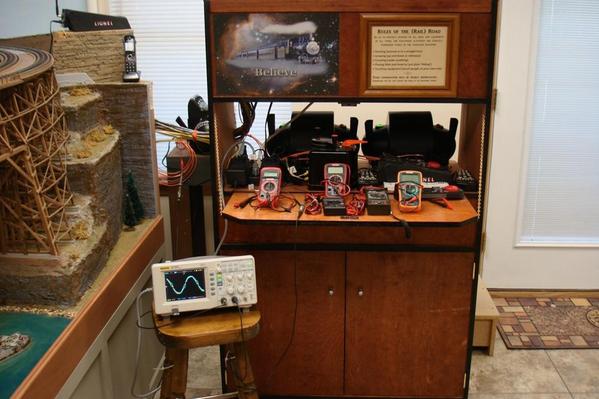
The three transfomers 

CONTROL CENTER DSC06718


Test equiment

CONTROL CENTER TEST EQUIP DSC06713


Old and new wiring of TIU's and transformers

ZWL with 2 Z4Ks


Thank you for looking!


Alex

Attachments

Images (12)
  • P0213-1 ZWL Alone - 5V Lbl
  • P0213-2 ZWL - Z4K Alone 10V Lbl
  • P0213-3 ZWL - Z4K Alone 15V-1 Lbl
  • P0213-4 ZWL - Z4K Alone 15V-2 Lbl
  • P0213-5 ZWL - Z4K Alone 19V-1 Lbl
  • P0213-6 ZWL - Z4K Alone 19V-2 Lbl
  • P0213-7 ZWL - Z4K Alone 19V-3 Lbl
  • ZWL-Y187 and Z4K-B187 V set LBL
  • ZWL-Y187 and Z4K-B201 V set LBL
  • CONTROL CENTER DSC06718
  • CONTROL CENTER TEST EQUIP DSC06713
  • ZWL with 2 Z4Ks
Last edited by Ingeniero No1
Original Post

Replies sorted oldest to newest

Thank you!  This is great.  Four of five years ago I took the Z4K to our lab and measured it and saw the slight "notchiness" around the zero crossing (the waveform departs on there from a real 60 cycle sine wave - it seems to hestiate and then plunge vertically across, etc.).  These do show why the ZW-L runs my conventional locos better though.


Again, thank, this is superb!

Originally Posted by Fec fan:

Cjack, if you are really curious, and have an hour or 2 to spend, read the Z4k patent: #6,281,606.

Thanks. I did/will look at it. It is clearly a pulse width modulated regulated supply. I'm not sure how it works in detail and I guess it doesn't really matter other than it looks cleverly done.

So in summary of my reading:


The ZW-L and Z4K at around 18v are very similar.  At lower voltages the Z-4000 maintains a closer sine wave, while the ZW-L clearly shows the pulsed power.  Both still runs trains very nicely, but newer trains may work better on a ZW-L at lower conventional voltages.


Thanks for taking the time to do the research and share.  Awesome post!


Jim

Here's the Lionel video guy in "Chop vs. Smooth Sine Wave".

Not being an EE, I gather these conclusions:

  1. Your smoke units and couplers work better when using chop when in conventional mode.(Lionel products)
  2. If you put either wave type through a TPC or a PM it comes out chop.

Is that the same for the TIU?


@Ingenerio No1-Did you test at the TIU or transformer?


Chopped or smooth may be good for some things, but if my train runs ok, I'm good.


Everyone - Thanks! Very glad to do it - as long as you find it helpful.


Moonman,

For the first set of tests I measured the voltages and connected the scope to the track - after the TIU's. Then I repeated the same tests at the transformer posts while they were connected to the TIU's and these were powered. There was no difference in the voltage levels or the traces. The traces I posted above (the last two, with the 'noisy' traces, were at the transformer posts.


The traces I obtained today were with the transformers not connected to anything.


Here is a bit more explanation on the scope traces for those interested.


The Z4K at 15V is close to a sine wave, so its peak value is the 15V times the Square Root of 2 (1.414) = 21.2V. The ZW-L is not a perfect sine wave at this voltage level.


P0213-3 ZWL - Z4K Alone 15V-1 expl


Thanks for looking.


Alex

Attachments

Images (1)
  • P0213-3 ZWL - Z4K Alone 15V-1 expl

Thanks, Ingenerio.

That helps me understand what the equipment is doing. Sorry I missed your earlier posts.

I appreciate your time and sharing the information.

Edit: I read your post with the first round of testing.

So, it would seem to me, that they are equal for DCS or Command operation. If you are running Conventionally, match the transformer and product manufacturer.


Last edited by Moonman
Originally Posted by Ingeniero No1:

Everyone - Thanks! Very glad to do it - as long as you find it helpful.


The traces I obtained today were with the transformers not connected to anything.


This is very helpful, Ingeniero No1.  It helps me understand how and why the ZW-L does so much better on controlling locos conventionally.


As to testing under load, for what is is worth, two data points.  Several weeks ago, John Zahornacky commented to a thread on the "voltage accuracy" of the ZW-L that that the throttle control ring is calibrated 0 to 20 at full throttle for hisotrical and legacy (small L) reasons, but that it was built to put out a maximum of around 18 volts RMS, so 20 = 18 volts RMS or thereabouts.  He said this would drop a bit - I recall the impress this meant 1/2 to 1 volt, no more, under load. 

    I measured voltage-drop-under-full load with a train that requires a full ten amps to run nicely (this is the Lionel Santa Fe Anniversary passenger set locos - ABBA set with four Pullmore motors, and in this case eight incadescent lighted cars).  At throttle setting 18 on the ZW-L the current flow starts the red light on the left side of the ZW-L blinking as the unit's voltage intervention kicks in (the second level of protection as described on the first two pages of the owner's manual).  At a throttle setting just below 18 - about 17.5 - the light is not blinking, the ZW-L's current meter says exactly 10 amps, while the unit's the voltage meter says 14.5 volts -- and a multimeter at the transformer terminals says 14.7.   At this exact setting with the no load the current meter of course says no current and the ZW-L's voltage meter says 15.5-16 volts RMS (can't read it any closer) and my multimeter says 15.8. 

Moonman, Lee –


Since I run only DCS and Legacy, I just move the handles of the ZW-L to the maximum since at this setting the voltage is around 19V and safe for the trains, as far as I know. (But I may be wrong )


On the other hand, I watch the Z4K voltmeters closely as depending on the load, the output could vary up to 22V or higher. Note that the actual Z4K voltage output can be 0.9V over the meter reading, so when the Z4K meter reads 18V, for instance, the actual voltage could be 18.0V to 18.9V. Very good meter indications, I would say.


During my testing I found that the meters on the Z4K’s closely matched the multimeter regardless of voltage level since the Z4K output is very close to a sine wave throughout. With the ZW-L, and was noted above, the output closely matches a sine wave only at the higher voltage levels, and some multimeters will not read correctly at the lower voltage levels.


Thx!


Alex


Originally Posted by Ingeniero No1:

Since I run only DCS and Legacy, I just move the handles of the ZW-L to the maximum since at this setting the voltage is around 19V and safe for the trains, as far as I know. (But I may be wrong )

I guess one could say that if 19V is a problem you will soon know.  I doubt it would although I never run any of my trains over an indicated 18V with the Z4K or ZW-L or a CW-80.


On the other hand, I watch the Z4K voltmeters closely as depending on the load, the output could vary up to 22V or higher.

I had a Z4K for years and mine also would go to 22V, not just no-load but even feeding a small load. Where I had installed it, I mounted wooden lugs bethind the throttle so it could not go past 19V no load (about 18V with a big load). 


During my testing I found that the meters on the Z4K’s closely matched the multimeter.

This was my experience, too.  The Z4K's digital read outs are more practical and useful than the ZW-Ls although the ZW-L's backlit dials look sexier to me.


With the ZW-L, and was noted above, the output closely matches a sine wave only at the higher voltage levels, and some multimeters will not read correctly at the lower voltage levels.

This is something all of us have to keep in mind and many seem unaware of.  Unless you get into realy expensive equipmment (Fluke, etc.), most inexpensive multimeters are designed with an assumptions they are looking at 60 cycle since waves, at low "voltages" (more correctly, throttle settings) the ZW-L is producing so many harmonics that they just don't see them correctly. 


Thx!


Alex


Thank you!  This is a very good and useful thread to me, and I am certain, to ma ny, many others!


Dave,

Thank you for reading it! I enjoy all of this stuff as well.


One point I wanted to reiterate is that I tried five different multimeters, and of these, three read the same or very close as the ZWL & Z4K voltmeters, but one read higher, and the other lower; and these differences varied according to the transformer voltage settings. The multimeters that read the same, or close, reflect the areas under the voltage curves, which are about the same for the Z4K’s and ZWL’s regardless of the peak voltage.


Thx!


Alex

Most voltmeters are calibrated for a sine wave. Anything else is likely to get an inaccurate reading.

   i watched the  Lionel sine / stepped video.  The smoke is a heating element. The heat is determined by the power no matter how you get that power. Also no mentioned is the fact that the stepped output, If not properly designed, can produce radio frequency interference. Don

Alex, Thanks for posting this. I had thought Z4Ks were also chopped sine wave. Obviously not.

Very good! Thanks for doing this. I wonder how MTH maintains a sine wave because I'm sure the voltage is electronically regulated.

From experience I can tell you Z4000s are not regulated. As the current draw increases from zero to 10 amps the voltage will drop. Also they are not regulated for input voltage either or if they are its over a very small range like 115-120 volts. Below 105 volts input it stops working. Not an issue for most here but our modular club sets up at a few venues (like local fairs) where power is a bit dodgey. Thats why we keep the trusty Post War ZWs on hand.


Pete

Well they are regulated, question is, how well? In addition to the droop of the internal connections and loose regulation, there are also voltage drops which contribute to the lowered voltage. For example, a 0.1 ohm resistance at an out put connector can contribute a 1 volt drop when going from 0 to 10 amps. In order to combat that, many high current power supplies bring out voltage sense leads to measure the voltage at the distant load rather than inside the power supply device.

I'm familiar with regulated power supplies. I have a number of them in my lab but by definition regulated means one of the components (voltage or current) remains within a small value of deviation over the rated range. I am going by the meters on the transformer itself. At zero current the voltmeter may read 22 volts with the handle at max rotation. At ten amps the voltmeter drops to 18 volts. In this case the meter readings have nothing to do with resistance outside the transformer.

I am open to "peer review". Anyone can try this experiment for themselves.


Pete

Pete, Russell -


I agree. And as far as the regulation goes, not all four channels of my two Z4K's exhibit the same degree of regulation, or lack of. One of the outputs remains between 19V-21V with currents from about 1A to 6A. But another output will vary 21V to 17V under similar load conditions.  The ZW-L appears to be better regulated.


Alex

The next phase of this should be a discussion of the theory of how this applies to PWM motor control and the different principles.  My understanding is the pulsing at high voltage has its advantages with initial torque for the motor.


Of course MTH and Lionel use two different approaches.  MTH converts this AC to DC at the fronted of the board and has the High DC Positive Voltage available at the motor, lights, coupler, smoke heater etc.., and regulates the return to DC ground to control the effective voltage down to 6V for lights, 12V? for motors.  I believe Lionel at least for TMCC stuff had the Ground available and pulsed the AC wave form going in to the motor, and for DC motor engine, convert the AC at the Motor Driver and still pulsed the positive DC.


So does the circuit design and algorithim for PWM determines which AC wave form is best for the as designed engine?   G

Post

OGR Publishing, Inc., 1310 Eastside Centre Ct, Suite 6, Mountain Home, AR 72653
800-980-OGRR (6477)
www.ogaugerr.com

×
×
×
×
Link copied to your clipboard.
×
×