I thought I’d post this info for anyone else who might find it useful.

A few months ago I purchased a new 6-85226 180 watt powerhouse from an authorized Lionel dealer. I intended to use it to provide power to a fixed channel on my TIU. Upon receiving it, to my great frustration, the circuit breaker would trip as soon as I turned it on EVERY TIME. I eliminated all the variables until I realized that The powerhouse didn’t even have to be connected to anything for the breaker to trip!

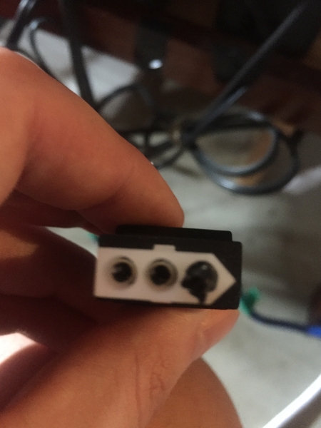
I was in the verge of returning it when I decided to stick both of the leads from my voltmeter into the molex connector plug and noticed it was registering high and low readings. Eventually, I decided to role up some electrical tape and put it in the molex plug hole that is “empty”, I.e. the hole that doesn’t have the connection through which the power would pass. Low and behold, the breaker stopped tripping when I would turn it on and it has both provided power and the circuit breaker has worked appropriately ever since. 

I have no idea why this occurred and unfortunatetly have forgot what caused me to think to put the electrical tape in the top hole but it has essentially served to fully/properly insulate something in the plug. Hope this solution may be prove useful to anyone else who may encounter this problem.

Original Post

Replies sorted oldest to newest

 It’s likely out of the time frame to return it to Gryzboski’s, with whom I’ve never had a problem(bought it early math or late February) but considering it was produced within the last 2 years I thought I’d be able to register it with Lionel- it’s still within warranty- but I was unable to do so on-line.

It’s worked completely fine every since I did the electrical tape thing, but considering that I have a pretty high opinion of both of you and your input now I’m a little concerned and think I’ll try to get this taken care of- whether through Gryzboski’s if possible or Lionel. Thank you for the input @gunrunnerjohn and @Adriatic

There's nothing wrong with the transformer. This was part of the redesign required for compliance. The transformer cannot have "live power" without the pin in that third position being pushed in. Per the manual, when connecting the transformer to something like a TIU, you have to install the included extra pin into the connector. Unfortunately there seem to be some transformers shipped without that pin included. If you call Customer Service, we can send that pin.

Or you can use electrical tape to replicate the pin 

@Dave Olson posted:

There's nothing wrong with the transformer. This was part of the redesign required for compliance. The transformer cannot have "live power" without the pin in that third position being pushed in. Per the manual, when connecting the transformer to something like a TIU, you have to install the included extra pin into the connector. Unfortunately there seem to be some transformers shipped without that pin included. If you call Customer Service, we can send that pin.

Or you can use electrical tape to replicate the pin 

I can honestly say that was abut the last thing I expected to read 🤔

But at least I read it 😋👍  

The breaker had me worried too.

Can you expand a little on that? Is it normal too?

@ Fellow Railroaders:

The code writers have actually given model railroaders a lot of consideration in the use of relatively high currents for train power, compared to the limitations placed on other low voltage circuits which can be found in residences.  Beyond that, we are trusted to devise our own acceptable practices to a certain extent.  We need to remain aware of the need to maintain that trust.  It is in that spirit I write on the safety aspects of the issue here.  I include no proprietary information, as I have none-- a life-long habit of not asking. 

I first posted on this subject 20 or 25 years ago, at the introduction of the 135 VA (volt-amperes) "power house" transformer (Lionel).  The problems of equipment damage occurred with cutting the special end connector off the PH (3-pin holes in house-roofed block as now).  Some users made conversion connectors to TUIs, avoiding PH changes (Note 1).

Damage occurred either to the PH or the TIU.  Information from users (85 cases of damage on OGR) was incomplete in key areas in most reports.  However, I could in two cases realize the two ways in which the 135 PH was being damaged.  I had opened my 135 PH (Note 2)-- its output to the track (21, to 18 volts at 10 A rated output passed thru a 10 A relay (Million Spot).  This relay had no published data as to whether it could be closed into a 10 A load, or open a 10 A load.  It was intended to do the latter at about 10.5 A according to others here.

I measured the maximum short circuit current this 135 PH could produce-- it is 105 A.  0r (Note 2, and if you contrive a dead short across the transformer in hopes of measuring 105 A you will destroy the PH.)

The two relays, of the 85 cases, had sufficient circuit and circumstance info  to say that obviously in one case, the relay contact had burned open, and in the other, had welded closed-- both at the users' layouts.  Some users identified the problem as a PH breaker defective at the factory.

For the 180 VA PH, I have been told it contains a 15 A relay.  I think short circuit current has been posted here (not necessarily proportional to the 135).  Still, I can say by inspection the relay can fail in the same way.  I have seen (it's been posted here) a diagram which at a glance I take to be an accurate time delay on the relay.  Some day I may confirm that and calculate the delay.  Or not.

At the time (of the 135 PH), the NEC code for Toy Transformers (see posts above) was changed, and a basic former requirement, that such transformer be able to interrupt any short circuit current it could produce, was simply dropped without explanation. 

There is a comment that the NEC is not intended to regulate the low voltage wiring downstream of such transformers, except (the transformer being 120v connected) that such transformers must provide all outputs arranged such that both all hot voltages and the common voltage  (usually the zero volts reference) be isolated from house, building, or other ground.  Further, the voltage difference at all times between any two outputs is limited to 30 volts (some parts of the NEC used 32 volts in past, but all now use 30).  (Note 3).

The  Toy Transformer code did not address the issue of powering a TIU with a PH because of the above policy.  However, there is a general policy that regulated equipment can only be used in accordance with the manufacturers instructions.  I can guess that there was a proposal by Lionel to provide "cascade" protection (for heavy shorts) downstream, as being less costly to the customer (you want to protect the first leads run from physical damage, and not lengthen it).  The unusual connectors tend to enforce this intent.

The 3rd contact on the unusual connectors appears either to have had a later phase-in, or was intended to be used if lack of the heavy short protection became a problem.  Most Lionel downstream equipment uses MOSFET chips to reduce track voltages (even if this feature is not used).  Such chips are very vulnerable to the high short currents of their PH source, to the extent that the MOSFETs must be self-protected-- the MOSFET itself is a most effective disconnect device, although in this application an adequate amount of heat sinking is very important.

There are still issues, however.  Most of the MOSFET control circuits I've seen here are set to interrupt only one side of the current sine wave, as the current zero is ending.  So there can be two full spikes of full current doing heat damage to wiring (at one time two pickup wires were joined within the engine-- the '54 Trainmaster being the first instance; I see it in recent post picture, altho I assume the board traces between are at last beefed for one full cycle.

There is still the question of voltage spikes.  Some chips in household devices have built-in protection for about 400 volts on a 120-volt circuit.  These are fairly common (meaning I've actually seen lines ring with whole trains of such spikes).  Here, the quickness of operation of the MOSFETs can result in spikes.  The current foldback circuits may help with this; or they may only deal with the 10 A limitation (which had a 60-second limitation last I looked years ago, meaning a motor starting current could be accommodated.  MTH used 24-seconds, and now in this GW that interval is 3-seconds.

So, with a connection to a TIU, there is the fuse I had said was necessary.  However, this is a 20-ampere automotive fuse not readily accessible.  There is a lot of saying this is a quick-blow fuse (ads?), but automotive fuses are actually slow-blow, as can be seen from the flat-ribbon fuse element.  So adding quick-acting magnetic breaker is indicated here as a minimum.  It may be inadequate in some conditions where the MOSFETs would not be.

The use of the Lionel trackside shed relay may be more appropriate in cases where a constant full voltage on the track is not a problem, and the TIU connected in the arrangement where it only injects the DCS signal to the track.  This limits the variety of engines which can be used, altho as to heat damage, the Lionel relay in the shed would operate subcycle based on its size (in my opinion only) unless it is deliberately delayed.  I've not seen any published data on this.  It is however, a compliant use of the equipment, IMHO.  (Note 4.)

You'll realize that operating in a mandatory insurance situation, such as a public show, some care in these issues is necessary.  This is particulary true in Minnesota.

--Frank M

Note 1:  Work-arounds will also be non-compliant when not in the instructions or otherwise permitted by the manufacturer.  To me this would mean you want to get the pin from Lionel and forget the tape. 

Note 2:  Do not open transformers or wire them except according to instructions (or ask advice). Leave this to qualified repair technicians.

Note 3:  This 30-volt limit is the maximum touch voltage for personal safety.  The issue arises when two or more transformers are used.  It is important that they all be properly phased (search posts re this).  IMO all the commons (only these) should be connected together.  Certain transformers require instructions or advice re common post.  Note that use of 12v dc on an AC layout creates a phase problem, suggesting a connected common to the dc circuit should not be used; that both dc conductors need isolation, insulation &protection.

Note 4:  For local users, the NEC is what the local inspector says it is.  (He is the authority having jurisdiction; or, his supervisor is.) END

Gunrunner-- Sorry to be so long in reply... I see that late Saturday night seems to be the only time I have to spend on the computer except for chores like taxes and today my wife cannot renew her car registration on line (our DMV requires reservation) because in 1967 she did not obtain a passcode.

So I see a certain time parallel in this to the two Lionel "brick" transformers, 135 va and 180 va.  You are quite right that the 180-watt unit has an elaborate control circuit, while the earlier 135-w unit did not have anything near this elaborate.  However, it did have a rudimentary circuit to open its 10 A (rated) relay (not a breaker).

This circuit required a short length of ni-chrome resistance wire in one of the low voltage output legs.  Reaching the rated 7 A output (apparently somewhat more as built and reported here) caused a sufficient voltage drop across this wire to cause the relay contacts to be opened.  A detection trace on a small board (1-inch square?} was run to the far end of the ni-chrome.  Measuring this time delay is not easy, but delay must occur when a downstream breaker needs open.

The contemporary downstream TMCC-optional "Power Controller" had similar ni-chrome wires. (But some had mis-wiring which negated the protection needed by the triac pairs used to create the partial waveforms for speed control, much discussed on an earlier board.)  I had one of these unit open to verify withstand over 1 cycle.

I have to correct my measurement of maximum possible short-circuit amperage output (105 A) as being that of the 135-w "brick".  I now remember it was measured on the 180-w unit much later.  By proration. max s/c would be about 75 A for the 135-w.  I believe you had a figure of about 100 A for the 180-w.

For other readers, the postwar ZW had deliberate leakage reactance and resistive coil rollers, so its volt-amperes (va)  ran rather higher than its useful watts output, and max s/c was about 45 A.  That is not the case with the current "brick" transformers, and faster short interruption is necessary but must be time-delayed for the first device in the Lionel cascade protection arrangement.

 I did not open the Lionel 180-w "brick" as I already had the circuit diagram for its control wiring.  I'll have to find that again, and see if Lionel has revised instructions on-line to show delay time as for GW.

I made an assumption that the two circuits I saw in the older 180-w were both timers, one on the plus phase and one on the negative phase.  Now I think I should look more carefully at them--possibly only one was a timer, and revise the previous post.         --Frank M

@F Maguire posted:

Gunrunner-- Sorry to be so long in reply... I see that late Saturday night seems to be the only time I have to spend on the computer except for chores like taxes and today my wife cannot renew her car registration on line (our DMV requires reservation) because in 1967 she did not obtain a passcode.

Tell me which state that is, because I never want to move there.   In PA we just go on-line and enter the VIN number of the car and we can renew our registration.  I never had a passcode, and I never needed one.

@F Maguire posted:

So I see a certain time parallel in this to the two Lionel "brick" transformers, 135 va and 180 va.  You are quite right that the 180-watt unit has an elaborate control circuit, while the earlier 135-w unit did not have anything near this elaborate.  However, it did have a rudimentary circuit to open its 10 A (rated) relay (not a breaker).

Too bad I sold my PH135's, because I had one open and it had nothing but the circuit breaker, it was an ordinary thermal breaker.  I saw no PCB of any kind in there.  I have no idea the vintage of the ones I had, I bought them well used.  However, I didn't like the poor circuit protection and I sold them.

@F Maguire posted:
I made an assumption that the two circuits I saw in the older 180-w were both timers, one on the plus phase and one on the negative phase.  Now I think I should look more carefully at them--possibly only one was a timer, and revise the previous post.         --Frank M

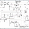
The PH180 circuit has two sensing circuits for the overload.  One reacts to a sudden spike in current and will cause an immediate trip, the other has a longer delay to allow the transformer to ride out a temporary power surge, say starting up a couple of MU'ed dual Pulmore motored locomotives.  You can actually demonstrate this on the bench if you have the proper equipment.  I use a huge heater for an industrial oven as a resistive load to test transformers.  On an immediate overcurrent of around 12 amps or more, the PH180 will trip instantly.  However, if you ramp up the overcurrent slowly, it'll give you several seconds before it trips. 

The late Dale Manquen actually posted this years ago, and it explains the operation as well as I've ever seen elsewhere.

In the schematic, both U1b and U1c are amplifying the current sense signal.  U1c, the "overload" detector, has a gain of 148, but it is slowed down by the resistor and capacitor on its output.  The time constant (RxC) is 2.6 seconds.  Multiple short hits to this RC combination would charge it up until it trips the relay latch. 

U1b has a gain of 37, which means it requires 4 times as much current, but it acts instantaneously for "dead short" situations.

Lionel Powerhouse 180 Schematic

Attachments

Images (1)
  • Lionel Powerhouse 180 Schematic

Quick update- purchased another ph-180, same sku from the same store and it had the same problem...and of course the same solution! I’ve started running my layout in passive mode ever since I bought a TPC 300 And TPC 400 over the summer. And @gunrunnerjohn , before you tell me I should’ve just bought the Legacy powermaster- the TPCs were $30 and $20 respectively. That said, Legacy PM is on my list down the road. Anyway, the circuit breaker protection in the PH-180s is amazing. The PH-180s are connected to the TPCs, the TPCs connect to MTH terminal blocks(TVs on each block) and I run an in-line fuse between the TPCs and the terminal blocks(1 for each). I use ATC, ATM and AGC fast-acting fuses- preferably 5amps but sometimes at 10. That said, when I use the 10amp fuses and there’s a short- the Powerhouse circuit breaker trips first 90% of the time. I don’t know if that’s how it should work, I’d assume that the in-line fuse would blow first, however that’s what happens. Regardless, point is that the tape trick worked again.

Last edited by StevefromPA

Add Reply

Post

OGR Publishing, Inc., 1310 Eastside Centre Ct, Suite 6, Mountain Home, AR 72653
800-980-OGRR (6477)
www.ogaugerr.com

×
×
×
×
Link copied to your clipboard.
×
×