
richs09 posted:

 Jerry - again, your work is really well done.  I'm curious about how you cut the shells - obviously the cuts need to be square and with minimal ragged edge.  I also see in your earlier post to this thread that you've added a thin piece of styrene to made sure all of the spaces between the windows are uniform.  What glue did you use?  Are the chassis done the same way -- cutting the original Gilbert chassis?


Rich,

I"ll try to be brief.  The shells were cut with a Zona type saw using a machinist square as a guide:

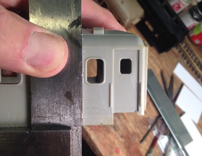
The other side was cut the same way using the square to make the cut.  Then a piece of tape to guide the saw on the roof:

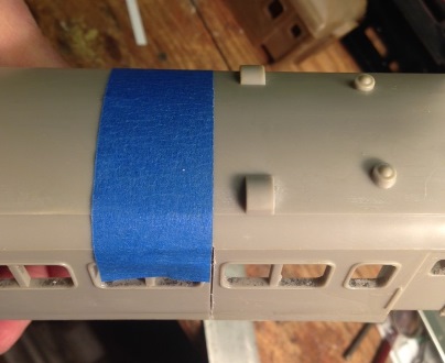
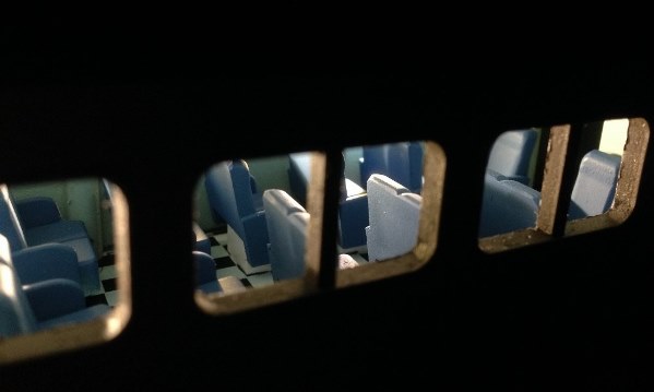
The piece of styrene to take the place of the saw width was cemented with MEK.  A thin piece of styrene sheet was also cemented on the inside for added strength.  When assembling the pieces, the car was trued up on a flat piece of glass to make sure it was straight in all directions.  A bit of filing may be necessary to keep it perfectly straight.  Then when dry, the gap and the filler piece was undercut slightly with a triangular jeweler's file and the resulting "gouge" filled with a mixture of styrene dissolved in MEK.  I used scrap pieces of the cars cut into small pieces then put in an airtight bottle with a little MEK.  After a few days, I stirred it with a metal spatula, either adding more plastic or MEK until the paste was the consistency of toothpaste.  It was liberally troweled into the gouge and allowed to dry for a week or more.  It will shrink, but after a week or more, it's completely dry and solid.  It then can be treated like the rest of the car since it was basically "welded" together.  A caution, howeverMEK is highly flammable and dangerous, so I did the mixing, etc. outside in the nice weather.  Lacquer thinner would work too.

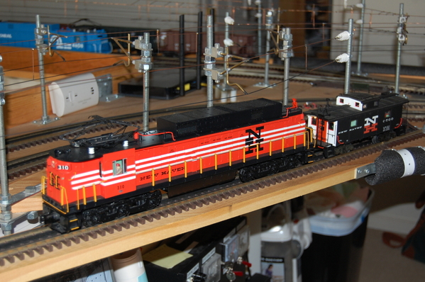
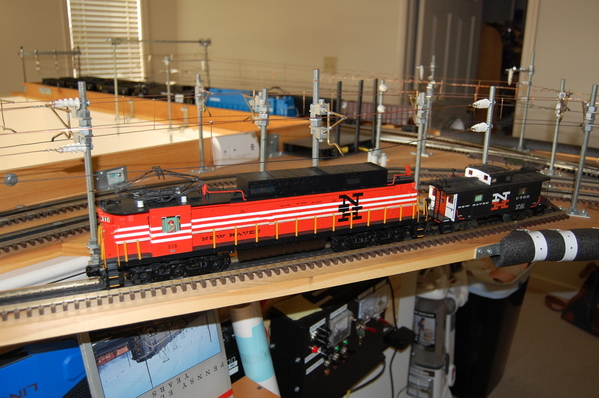
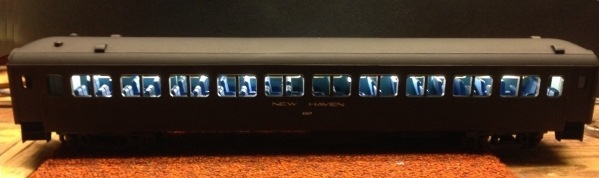
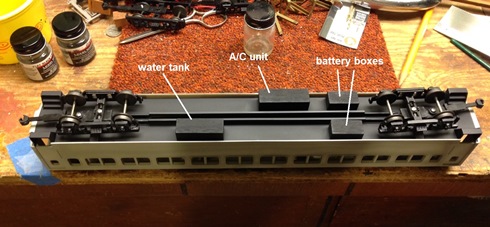
As to the frames, since the originals are either sheet metal or die cast, it was easier to make new frames from .060" styrene sheets with styrene channels for the frame rails and bars for the bolsters.  I added wooden blocks to simulate the battery boxes, water tanks and A/C unit.  After all, I was just trying to simulate a "what if", not a contest model.  As I said before, sometimes close enough is good enough:

And thanks for the link to the circuitry.  It will come in handy.  I have dozens of LEDs taken from an on-sale, after Christmas light string.  Hey, I'm cheap!  I usually use a Gilbert transformer and the LEDs are 3V max.

Sorry for being long winded again.  Maybe others can use some of my suggestions.  Isn't this what this forum is about?

Attachments

Images (3)
  • blobid0
  • blobid1
  • blobid2
richs09 posted:


In terms of lighting, as I suspect you know, there are a number of posts about circuits and wiring up LED strips.  One of the more recent is here, which is a reference to GRJ's constant current circuit. f

I tried to find a way to contact you directly, but couldn't find your email.  The circuit described is too large to fit anywhere.  Besides, the vestibules on the cars are open.  Thanks anyway.  I guess I'll simply use a small diode bridge and resistor.

Seacoast posted:

Melgar,

I like how simple the layout tack plan is, and it’s very highly detailed! Outstanding work!

The track plan had to be just an oval because I wanted a minimum of O-54 curves and the table is five feet (60 inches) wide. With the scenery items that I wanted to include (town, bridges, factories, creek, tunnel/hill) and the ten foot table length, there wasn't even room for a siding.

MELGAR

Last edited by MELGAR
Seacoast posted:

Melgar will you be expanding or is the layout finished. Again a Well done layout!

I'm considering a four-foot extension at the town end. The layout is modular, built on two five-foot by five-foot pieces of plywood covered by up to five inches of extruded pink foam. It is designed to be lightweight and transportable. The plywood/scenery can be lifted off the benchwork and the buildings, bridges and even the tunnel/hill can be lifted right off the layout if it has to be moved. The benchwork is modular (by Mianne) and can be disassembled with a screwdriver. The modularity will be maintained if I add the extension.

MELGAR

MELGAR_2019_0508_01_10X5_OVERVIEWMELGAR_2019_0509_03_NORTH_SIDE

Attachments

Images (2)
  • MELGAR_2019_0508_01_10X5_OVERVIEW
  • MELGAR_2019_0509_03_NORTH_SIDE

Although I live in CA, I became a life long NH fan as a child visiting my grandparents in Fairfield, CT.  They took me to my first baseball game (Brooklyn Dodgers vs. St. Louis (?), first Broadway play, etc., on the NH.  My grandparents were big Dodger fans and hated those Yankees.  They became Mets fans after the Dodgers moved to LA.  For some reason they never liked the Yankees.  

I went to the TCA convention in Warwick, RI a couple of years ago.   I rented a car and drove to Fairfield to see our old family home and visit my grandparent's graves in Bridgeport.   I took these photos of the Fairfield station during that trip.  Much has changed and much is the  same.  Many of my childhood greatest adventures and memories started in the buildings shown below.  NH Joe

DSCN0862


The NH railroad (now Metro North) runs east and west along the shore line of Long Island Sound.  This is the station building on the north side of the tracks.  We would take the train from this side to ride a west bound commuter train to New York.  Note the salt box design of the station.  I don't recall seeing any models of these salt box stations buildings although it was a very common design on the NH.   The building is in much better shape now than in my grandparents day.  This parking lot was dirt then.  We had to wade through snow and mud to catch a train during bad weather.

DSCN0905


Here is another view of the north station taken from across the tracks.  Note the high level platforms.  All the platforms were at track level in the NH days.  

DSCN0866


Here is another view of the of the north station looking down the tracks toward New York.  Note that the 100 plus year old NH catenary towers are still being used.  The NH triangle wire has been replaced by a modern wire system.  Only one of the four tracks on the mainline has concrete ties.  This route is used daily by Amtrak Acela trains.  I don't know what the speed limit is in this area.  I remember seeing NH expresses roaring through here.  They always seemed to me, as a young boy, to be going faster than a speeding bullet.

DSCN0873


Here is a photo of the south station building.  It is brick.  People would catch the train on this side of the tracks to go east to Bridgeport, New Haven and Boston.  The building had a taxi company and a pizza parlor inside when this photo was taken.

DSCN0860

Here is another view of the south side station building.  The entrance to the pizza parlor is under the sign on the right.

DSCN0883

Here is a track side view of the building as seen from across the tracks.

DSCN0885

Here is one of the trains that I saw that day.  It is heading west toward New York.  This is the end of the train.

DSCN0890

Here is a view of the tracks looking east toward New Haven and Boston.  Note the pedestrian bridge.  That bridge was a very shaky wooden structure back in the day.  I have crossed it many times.

DSCN0867

Here is a view of the tracks looking west toward New York.  Note the large radius curve for high speed running.  It was a thrill to see an EP-5 towing the Merchants Limited racing along these tracks.  

DSCN0865

Here are a few photos of the interior of the north side station building.  Back in the day, this interior was smoky and dingy. It has been beautifully restored.  The restoration may be better than it was when new.

DSCN0902

DSCN0911

DSCN0898

DSCN0899


Attachments

Images (15)
  • DSCN0860
  • DSCN0862
  • DSCN0864
  • DSCN0865
  • DSCN0866
  • DSCN0867
  • DSCN0873
  • DSCN0883
  • DSCN0885
  • DSCN0890
  • DSCN0898
  • DSCN0899
  • DSCN0902
  • DSCN0905
  • DSCN0911
Last edited by New Haven Joe

With the Holidays here, trains are on the proverbial back burner.  However, I was able to finish up all six cars' seats and am in the process of interior lighting.  LED strips will be on the ceiling, but for now, I wanted to see what it would look like.  So I put the LED strip on the side  to light up the interior.  I'm not sure if I'll apply the LED strip directly to the inside of the roof, or put a wooden strip up first and then affix the LED strip to the wooden one.   Either way, there's not a lot of room for fancy electronics.

Attachments

Images (3)
  • blobid1
  • blobid2
  • blobid3

Add Reply

Post

OGR Publishing, Inc., 1310 Eastside Centre Ct, Suite 6, Mountain Home, AR 72653
800-980-OGRR (6477)
www.ogaugerr.com

×
×
×
×
Link copied to your clipboard.
×
×