Have owned since new in 2000.  Tried running it in conventional mode years ago.  As I recall it moved but after a short bit of running, quit.  It was on complex switchwork, so a short could have happened even though I don't recall sparks or tripping a breaker.  Did not try DCS at the time.  Has been on the shelf since then, because it wasn't a priority for running at the time.

Today, placed on my DCS test track with confirmed good signal using another PS2 loco just before.  On powering up track, engine remains dark and silent.  When trying to set up in DCS remote, allowed one minute for BCR to charge, then tried to "add MTH engine."  The error message is "no engine found".  18 volts at track, freshly cleaned track, just nothing.  It has a BCR1 that I installed in place of the 8.4v battery years ago before sitting on shelf, meaning it has the older 5 volt board, I gather.  Cannot remember whether BCR1 went in before or after the brief conventional test run.  I know I had not charged its battery before running, if it still had the battery.  Have added multiple other PS2 and PS3 engines to this same TIU and remote recently with no problems.

What's next to evaluate? Thanks

Original Post

Replies sorted oldest to newest

As with any MTH engine- monitor current draw when powering.

Most likely it's dead, just like the dozens and dozens of others for sale on ebay and so forth. This is a well known failure.

Again, basic testing, any engine really.

You power up on a conventional only track, no DCS and check for current draw. Either really high or really low- more like none at powering on. If you have none- it's already burned out so badly the circuit is open.

Be careful recommending the PS32 board, it may be a tight fit.  Also, at least one of the harnesses may have to be lengthened to reach the connectors.  I just put a 3V board I had in my MTH Q2, I looked at the PS32 board, but it was going to be a significant PITA to fit it in there.  The 484 is a smaller boiler, so it could be problematic.

Yip, I recall wires had to be extended, board mounting different too.  Not a show stopper.

Jim

Thanks for the responses.  On conventional test track at 16v, current draw is absolutely zero.  So, dead.  I read the PS3 conversion kit installation instructions online this morning.  Even for someone experienced with careful attention to details around electronics and a few TMCC conversions done, the opportunities for something to damage the board are notable.  Cost for professional installation plus shipping are considerable.

The ERRCo conversion to TMCC with Cruise Commander board and Heavy Steam sounds looks like a good match, and I know that work already.  Thoughts on that choice?

Unless you're willing to dispense with chuffing smoke, you'll have to spend additional money and time for the full TMCC upgrade over the PS/3 upgrade.  You need a chuff switch, and for chuffing smoke, you need to add a controller to manage that.

Obviously, if you go TMCC, I'd recommend my products for the chuff and smoke control, the Chuff-Generator and the Super-Chuffer II.

As long as your module comes with instructions (suspect it does), would prefer yours along with your Chuff-Generator.  How do I order? I happen to have the ERRCo boards in hand, turns out the heavy steam is not suitable for the engine I had it for but perfect for the UP 844.

Do all ERRCo steam boards need additional hardware to control chuffs per revolution?  If so I might need more of your items. Thanks

If you don't have a chuff switch, then the ERR stuff requires you add one.  You can do that in a variety of ways, however I personally found the other methods unsatisfactory and less reliable.  I used to put four magnets on a driver with a reed switch, but that sometimes was difficult, in an extreme case, I had to drill countersunk holes for the magnets to clear the frame.  You can also put a magnet on a tender wheel and a reed switch on the truck to generate the chuffs.  For Lionel with 2-chuffs, some folks have 3D printed a cam to make the chuff switch generate 4 chuffs.  However, I chose to go another way and design the Chuff-Generator.

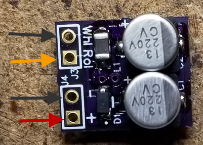
My little power supply isn't a "stock" item, but I can sell you a couple.  I don't actually have instructions for it, but it's so simple that I never saw the need.

AC-DC 5V 100ma Power Module Annotated

Frame ground is the black arrow, and that's common with the negative output of the supply.  Since TMCC chuff signals are frame ground referenced, it's mandatory for the negative DC output voltage also be frame ground referenced.

The orange arrow is the track center roller input power.

The red arrow is the 5VDC output.

The DC outputs go to the power inputs of the Chuff-Generator, the chuff output of the Chuff-Generator replaces the mechanical chuff switch.  The chuff Generator only has three connections to the locomotive, 5VDC power, ground, and the chuff output.  In the graphic below, the red is the power, green is the chuff output, and the blue is ground.

Attachments

Images (2)
  • AC-DC 5V 100ma Power Module Annotated
  • mceclip0
Last edited by gunrunnerjohn
@cnwdon posted:

Very clear, thank you.  Where should I go to order the chuff generator and power modules?

You can get them from me.

@GGG posted:

Know unit to fail.  I have put plenty of PS-32 in the shell to retain all functions.  It can be done.  G

Since George has MS-32 boards, that's the cheapest way to go and restore full function.  It's also a lot less work, even if you do it yourself.

Thank you both.  Have sent George an email requesting info re: PS 3/2 board.  

GRJ, I will need your chuff generator and p 5v power module for two other locos I’m doing with ERRCo.  Maybe three or four, if they can be added to any of the oldest TMCC locos that only have one chuff per revolution.  I see the chuff generator on the Hennings/JW&A website.  

How should I go about paying you for the power modules, 2 (or more as above) of them?

Also I see two different TMCC battery replacements.  They look like capacitor packs, as I would assume they would be.  What are the applications for the “regular” and “lite” versions?  And do they help with chuff “drop-out” as happens even with clean track and no apparent reason?  A charming little behavior that I would love to do without.

Lots of questions, as usual Thanks

Don

Like I said, drop me an email and we'll fix you up with the stuff you need.

As for the batteries, they are identical in function, the only difference is one has the 9V battery clip, and the other has the mating connector for the RS-Lite board used in Legacy equipment, and also used with the ERR RailSounds Commander.  The one with the 9V battery clip is used for TMCC and early Legacy applications that have the 9V battery cable.

The whole purpose of the YLB is precisely what you stated, especially for TMCC/Legacy steamers with the wireless drawbar.

Add Reply

Post
The DCS Forum is sponsored by

OGR Publishing, Inc., 1310 Eastside Centre Ct, Suite 6, Mountain Home, AR 72653
800-980-OGRR (6477)
www.ogaugerr.com

×
×
×
×
Link copied to your clipboard.
×
×