
This stared out in a discussion on the LionChief forum that got pretty far away from the original topic being discussed.  I thought it best to start a new topic to post what I've "discovered".  The original thread can be found HERE.

Anyway,it came up that the manual for LionChief Plus engines states hat they should be powered by no more than 18.0 volts or they could be damaged.  This was a non issue as the engine's owner was planning to use a Lionel transformer that would supply only 18 volts, however I commented that if higher voltages could damage the electronics of the engine, then caution should be taken with other manufacturer's transformers that are capable of supplying higher voltages.

The premise is that with a so-called chopped wave transformer, the electronics of the engine will 'see' the full output voltage even when the throttle is set to a lower level.  Because of this, electronics that could be damaged by higher than recommended voltages could be damaged even if the track RMS voltage is set to a lower level than the recommended voltage limit, because they would still see the full level that the transformer is capable of supplying.  

For my test here, I used a Z1000 with Zcontroller as my supply source.  (As a side note, under even a tiny load this transformer would reach only 18.5VAC at full throttle, but without a load it reached 19.5VAC.)  I constructed a simple circuit to mimic the circuit at work in almost all devices that convert AC power into DC.  After opening up my LionChief Plus NW2 I can confirm that this engine used the same setup.  

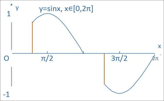
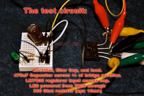
AC from the transformer is passed through a bridge rectifier which converts it into a DC current of varying voltage that rises and falls in time with the cycle of the incoming AC.  A 470uF capacitor was then placed across the output of the rectifier to filter this pulsating current into a smooth, steady DC current.  ( I can again confirm that the LC+ NW2 uses this same bridge and filter capacitor to produce the DC on which it operates.  The NW2 uses a 1000uF capacitor.)  From here I used an LM7805, an LED, and a 330 Ohm resistor to build a tiny load to drain the filter capacitor so that I could get better readings.  

To measure and collect data I used two volt meters.  I used my reasonably good quality meter to measure the AC voltage coming out of the Zcontroller.  This meter measures true RMS, unlike the free meter I used for the DC measurement.  A free meter from Harbor Freight was used to measure the DC voltage across the filter capacitor.  This meter is not very good, but when compared to my good meter it reported DC voltages within 0.1 volt of the assumed true value,  good enough to prove the concept here.  

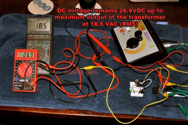
Here is the test setup:  

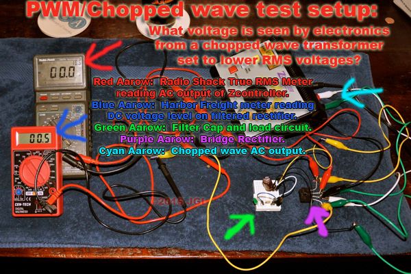
This setup fairly accurately mimics the bridge set-up inside my LC+ NW2.  I repeated this test probing the connections on the engine's circuit board and found nearly the same results.  The voltage reading were within 0.5 volts of what they are in the sample circuit.  I tried to take some video of the actual engine being tested, but could not hold the probes on the board, adjust the transformer throttle and film at the same time.  Suffice to say that the electronics inside that engine see similar voltages with the Zcontroller set to the same levels.  

The experiment started by nudging the throttle up until any voltage was read on the transformer's output.  It appears the Zcontroller kicks on at about 2.5 volts (AC RMS).  Here at this bare minimum voltage from the controller we already read well over 14 volts DC being supplied.  

The DC voltage rises with the AC voltage up to about 10 volts (AC RMS).  I suspect it is really closer to 9.75 volts, the half way point of the controller's full, no load, output.  At 10 VAC the DC has reached 26.9 volts. After this point the DC voltage will rise no further.  The filter capacitor is receiving a full half of the AC cycle, effectively receiving the same energy it would with a single diode under half-wave rectification.  

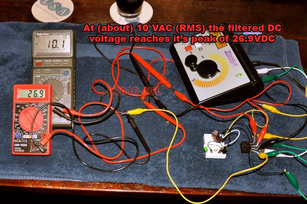
The DC voltage remains 26.9 volts as the controller is turned up to its maximum level of 18.5 VAC.  

Here we have it in real time, a short, poorly lit video of the voltage readings as the throttle as it is turned up and back down.  Aside from simply watching the meters, you can see that the green LED turns on the moment the Zcontroller is turned above zero and remains on until the controller is zeroed again.  This is only of note because the 7805 regulator that powers it requires 7 volts DC to turn on.  

The conclusion that can be reached is that the electronics running off of DC power inside your engines are going to see a significantly higher voltage than the RMS voltage of the AC would suggest.  further, at anything past half throttle they will see the full, peak voltage the transformer is capable of providing.  This means that the electronics must be capable of handling this peak voltage if you use a chopped wave transformer.  A chopped wave transformer that is just turned down will still apply full voltage to the electronics.  

As a side note, this is why I believe early ProtoSound locomotives do not work correctly on these 'chopped wave' transformers.  They are designed to read track voltage with a simple AC to DC converter like this, and as such will never see low enough voltages to start up, the electronics read as if the throttle is at full when it is only barely turned up.  

As a second note, I've been tracing out the boards of my NW2, and so far I've found nothing that could be damaged by less than 24 volts of full wave AC power. When I have a bit more information on that I'll post it over on the LionChief board.    I am pretty sure that the electronics in any engine from one of the major manufactures will be just fine with 24 volts or less of full wave power ( < 35VDC peak voltage).

JGL

Original Post

Replies sorted oldest to newest

By "chopped", I assume you are talking about what some call "shark fin", in which case, I agree.

The RMS voltage of a full wave rectified power supply = The AC RMS voltage - voltage drop in the bridge rectifier (typically 1.4V)

The peak voltage = 1.414 x the RMS value (of the bridge output).

The shark fin controller will hit maximum peak value at the theoretical half throttle position.

There is another factor that will help to hold down the DC voltage; that is the source resistance of the transformer. The peak current that occurs twice on every AC cycle can be quite high, so the peak output voltage of the DC supply will be reduced.

However, if there is little to no loading of the DC circuit, this reduction will be insignificant.

A general "rule of thumb" for this type of power supply is to multiply the above peak voltage by .85 or .90

So peak voltage = 0.9 X (18-1.4) x  1.414

This type of power supply will have a few of volts of ripple on the DC output. If you set your true RMS meter to AC volts, you can measure it.

I could go on, but I'll stop here.

JohnGaltLine posted:

snip...

The conclusion that can be reached is that the electronics running off of DC power inside your engines are going to see a significantly higher voltage than the RMS voltage of the AC would suggest.  further, at anything past half throttle they will see the full, peak voltage the transformer is capable of providing.  This means that the electronics must be capable of handling this peak voltage if you use a chopped wave transformer.  A chopped wave transformer that is just turned down will still apply full voltage to the electronics.  

As a side note, this is why I believe early ProtoSound locomotives do not work correctly on these 'chopped wave' transformers.  They are designed to read track voltage with a simple AC to DC converter like this, and as such will never see low enough voltages to start up, the electronics read as if the throttle is at full when it is only barely turned up.  

As a second note, I've been tracing out the boards of my NW2, and so far I've found nothing that could be damaged by less than 24 volts of full wave AC power. When I have a bit more information on that I'll post it over on the LionChief board.    I am pretty sure that the electronics in any engine from one of the major manufactures will be just fine with 24 volts or less of full wave power ( < 35VDC peak voltage).

JGL

Excellent.

JohnGaltLine posted:


Anyway,it came up that the manual for LionChief Plus engines states hat they should be powered by no more than 18.0 volts or they could be damaged.  

Hi John -

You analysis is sound and about what I would expect, but, to further your point, my Lionchief Plus manuals do not make any statement similar to the dire warning quoted above. Indeed, some of the Lionchief RTR set manuals tell you to push the throttle all the way up when using a transformer instead of the included power pack. They mention 18 VAC in parentheses, but there is no warning of any sort about exceeding that value. I have not read each and every manual but have made a representative sampling. 


It is a little hard to believe that a manufacturer of a consumer product would design anything so "tender," but it is possible I suppose. Did Lionel actually state this 18.0 volt absolute limit, or is this "tribal wisdom" run amok?

Last edited by PLCProf
PLCProf posted:
It is a little hard to believe that a manufacturer of a consumer product would design anything so "tender," but it is possible I suppose. Did Lionel actually state this 18.0 volt absolute limit, or is this "tribal wisdom" run amok?

Look in the manual.  TMCC and Legacy state 19V maximum.

From an LC+ manual.

You may choose to control your LionChief Plus locomotive with the included LionChief remote (using a transformer or power supply capable of supplying a constant 18 VAC or 18 VDC to the track) or using a conventional three-rail AC transformer with a throttle and whistle/horn and bell button.

Sounds like Lionel thinks you need 18V.

gunrunnerjohn posted:
PLCProf posted:
It is a little hard to believe that a manufacturer of a consumer product would design anything so "tender," but it is possible I suppose. Did Lionel actually state this 18.0 volt absolute limit, or is this "tribal wisdom" run amok?

Look in the manual.  TMCC and Legacy state 19V maximum.

I trust you on that. But I want to see the 18.0  volt maximum for LC+, cited as the basis for this thread.

From an LC+ manual.

You may choose to control your LionChief Plus locomotive with the included LionChief remote (using a transformer or power supply capable of supplying a constant 18 VAC or 18 VDC to the track) or using a conventional three-rail AC transformer with a throttle and whistle/horn and bell button.

Sounds like Lionel thinks you need 18V.

Yes, I wouldn't run them on 24 or 30 or anything like that. But I take that statement to mean a nominal 18, maybe plus or minus 10 or 15 percent. The concept that   18.5 or 19.0 is going to be the end of the world is very difficult for me to accept. 

Putting my money where my mouth is, I am running my LC+ stuff on an LW turned all the way up. Just for giggles, the throttle handle markings say max out is 20 volts, but the fixed voltage tap calls the same voltage 18 volts, and the service manual shows a total of 19 volts at that point! Same electrical point, but Lionel has 3 different voltages on it!  In actuality, it varies from a little over 20 at no load to something less than 17 at full load. We will see what happens, but I am not concerned! No TMCC or Legacy on this one, however.


Lets see, in order of posts:

OMAN, By chopped I'm meaning the typical waveform created by electronically controlled train transformers whether they use FETs or Triacs to pulse the output.  I'm sure there are slight varnations in the actual waveform among the various types.  I think that the over-all shape of the wave will have little effect on the filtered DC level with any waveform we are likely to see from a transformer capable of supplying enough energy to operate an engine.  Here's the first image I could find on the net showing a typical 'chopped' ac waveform:  

Your math is pretty much in line with what I expect as well.  I found that the DC load, however, had little to no effect on the voltage across the output of the bridge, even when testing on an actual engine with the load of the electronics, sound system and motor running.  

Dale Manquen,   Right you are, the 7805 will give erratic output at various levels until about 7v is applied, This ma be enough to turn on the LED even when less than 7VDC is applied.  I din't really think it through all the way, mostly because in this test the regulator never saw less than 14 volts to it's input, even at the Zcontrollers lowest possible setting above zero.  

PLCPROF, it seems you are correct.  As it turns out I based the premise on other folks providing correct information in the other thread.  Looking over that manuals for my LC+ engines as well as a couple of others online I can find no such warning not to exceed 18V.  If I recall some ERR or TMCC products do warn not to exceed 19VAC, so the same logic would apply.  I suppose over all this topic has less to do with the actual engine in question in the other thread, but is more of a general information sort of post, as lots of folks don't really understand what is going on with these sorts of transformers.  

GRJ/PLCPROF,  My guess is that Lionel wants to sell Lionel transformers which provide 18 volts.  With as much of the LC+ NW2 board figured out as I do at this time, the limiting factor I see is a 35v 1000uF capacitor. every other part on the LC+ electronics that receives unregulated power appears to be rated for 40VDC or higher.  Worth noting that the smoke unit also receives the unregulated DC supply, so if there is anything there that can be damaged by high voltages it may be a limiting factor as well. I've not looked at the smoke unit's design as of yet.  

Unregulated DC is supplied to the HEXFETs for the motor drive, the smoke unit, to a switching regulator set to 5.5 volts, and to a voltage divider that feeds voltage information to the processor for conventional control.  The voltage divider appears to be clamped with a zener diode to prevent over-voltage to the processor.  

To all, Thanks so far for the interesting discussion, which is what we're all after here, I think.  

JGL

 
Last edited by JohnGaltLine

So we can conclude every Train circuit board uses a FWBR for all board power.  All Transformers use Shark Fin or Z-1000 circuitry and therefore....???

I have not reverse engineered a LC/LC+ board.  So I can't fully speak to any limitations.  But John, why don't you get a 24VAC transformer and do an endurance run on you NW-2 LC+  See if it can handle the 24VAC long term.  Maybe operate some accessories so you can generate some voltage spikes from the 24VAC RMS start point.  That can help confirm or debunk the LC+ Limit.  Then you can try it with a Legacy Engine since they are all the same.

Now, I have reverse engineered MTH PS-2 boards.  Here is what happens when you use a Z-4000 as input to a PS-2 3V Power Supply board and Measure the PV (Positive Voltage) DC output.  Here is the caveated though.  The FBWR IS NOT the power Source for the Circuit board Electronics.  You could clip it off and still run the electronics. So I guess all circuit boards are not the same.

So where does DC Voltage come for the circuits?  Old LCRU used a single Diode to drive a VR.  MTH uses a dual Diode to drive a VR, I have seen boards with multiple DC VR Driving many different components.

For MTH PS-2 PV Only drives Motors, Couplers, Smoke Heat, and Lights. This is what I am going to measure since it mirrors your assumption of the FWBR.

Anyway, the Z-4000 kicks in about 9.4 VAC and you measure 14VDC.  At 12VAC your 14.5VDC, and 14VAC your about 16.8 VDC and at 18VAC you get to about 22.5VDC, when I push up to 24VAC I got about 30VDC.  So for some reason the result is not the same as yours.   At lower throttle settings and actual Train Power Supply board did not do the same as your Bridge Rectifier circuit with a Z-1000.

Could it be those Zener diodes on the output of the DC regulated circuit?  Could it be the Z-4000 AC Output behaves differently than the Z-1000 based on throttle input?   Weird stuff.

If a Post War Transformer is used and you set the throttle to 12VAC RMS Output do you still see peak 24VAC?

Have you tried a Z-1000 that has a 24VAC output brick?  Does that controller regulate the same?

I do believe Lionel transformers Chop providing peak voltages, part of their design, but they do limit the Transformer AC input to 18VAC.  Which was the original premise in the other post.  I think you just need to be careful with your assumptions.  Not every board or transformer design is the same.   G


GGG,  

I have to ignore any readings taken with a Z4000 as the power source, as this transformer is NOT a chopped wave output.  The Z4000 is a unique beast in that it provides what can best be described as a stepped sine wave.  If you look closely enough at the wave form, it is a series of steps that roughly imitate the shape of a sine wave.  in effect, this transformer's output behaves pretty much the same as a true, pure, sine wave transformer.  The peak to peak output voltage of the Z4000 actually varies just like a post-war transformer does, so any DC filter can only charge to that peak voltage.  What this means is just that using a Z4000 is useless to this discussion as it does not suffer from the issue of full output peak voltages.  For all practical purposes the Z4000 behaves as a post-war transformer, not a 'chopped wave' transformer. 


As for running my LC engines at higher voltages, I'm not opposed to doing this once I finish seeing what's going on, as stated above the limit appears to be 35VDC, though I need to insure that the smoke unit can handle that voltage.  Honestly, however, I have no need to do so.  Understanding component level electronics I know that the motor driver can handle up to 55VDC and has clamping diodes in place to protect from back emf.  I can also see that the unregulated DC makes it's first stop at a switching regulator that is rated at 40VDC max input.  I can also follow the trace for conventional voltage detection and see that a zener diode is in place to clamp the voltage there to protect the electrons from excessive voltage.  The electro-couplers do in fact have their own rectification to power them independently from the bridge used for the rest of the engine.  

Basiclly I think there are two sorts of folks when it comes to electronics… those that can follow a recipe, and those that don't need one to cook.  if you understand electronics at a component level, where you are capable of designing a board that can mimic the functionality of those in our train engines, you should be able to follow this post quite well, and understand how a low-pass filter works, and what output you would expect to see from one with various inputs applied.  

Now, I am open to the idea that some board or other may use some method other than a simple rectifier and capacitor to filter AC into DC, but I'm unsure why such a method would ever be used.  It really makes no difference if a bridge or a single diode is used, the result is pulsing DC.  Capacitors are cheap and easy, and do the job of filtering this pulsing current perfectly (or good enough for it not to matter if they have a bit of ripple).  If there is a board you are aware of that uses some other method to convert pulsed, rectified DC into filtered, constant DC I'd like to see it.  


As for accessories and transient voltages, I think this falls outside of the scope of transformer output.  These voltages are much higher than any provided by a transformer, and have nothing to do with the transformer, but rather with collapsing magnetic fields in the switches and accessories.  These can occur no matter what rms or peak voltage is applied to the track, and the best solution, as I'm sure you're aware, is to place TVS diodes about your layout, and/or inside the engines themselves.  

JGL
 
Edit:  upon thinking further the HEXFETs in use for the motor driver may not like voltages over 25vdc.  They are rated for a 20v gate to source voltage difference, so may be damaged if input voltage is too high.  Need to do a bit more research on this still.  
Last edited by JohnGaltLine
JohnGaltLine posted:

GGG,  

I have to ignore any readings taken with a Z4000 as the power source, as this transformer is NOT a chopped wave output.  The Z4000 is a unique beast in that it provides what can best be described as a stepped sine wave.  If you look closely enough at the wave form, it is a series of steps that roughly imitate the shape of a sine wave.  in effect, this transformer's output behaves pretty much the same as a true, pure, sine wave transformer.  The peak to peak output voltage of the Z4000 actually varies just like a post-war transformer does, so any DC filter can only charge to that peak voltage.  What this means is just that using a Z4000 is useless to this discussion as it does not suffer from the issue of full output peak voltages.  For all practical purposes the Z4000 behaves as a post-war transformer, not a 'chopped wave' transformer. 


I have not used a Z-4000, but I have read the applicable patents cover to cover.

According to the patents, the Z-4000 basically passes the raw AC to the output, so it maintains the phase and frequency relationship with the power line, but applies PWM along the way, so the output is a sine wave interrupted several thousand times a second. The duty cycle of the interruptions determines the effective output voltage. There is no DC stage and the output is not synthesized. 

There is a great deal more nicety to it, the pulses and interruptions are smoothed  by some inductive/flyback filtering in the style of a forward converter in a computer power supply, but that's the crux of it, or so the patent says... Completely different from a Z-1000 or CW-80

So what is the point of all this?  I thought the original premise or thesis JGL posed was all transformers are the same and all Circuit boards use basic filter FWBR DC.  Therefor all circuits see Peak Voltage at lower voltage settings anyway; therefor these manufacture posted limits don't matter?

Or are we just proving that a capacitor can see the peak voltage passed and store energy at that level?  As long as the load is not such that it drains before the next peak is applied?  Or are we proving a single silicon diode drops .7V and a pair drops 1.4V?

I find this all useless to the application of running trains and solving problem when applied in a generic way.

We have merge the topics of what is the voltage limit on Lionel products (purely based on Failure criteria of a component vice circuit not working as designed, or reduction of life), how transformer chop input and how circuit boards work into one topic summarized as a conclusion based on a single replica Circuit, and a Z-1000.  My use of a different power supply/circuit board (a real one used in a real train circuit) and a different transformer are thrown out because they don't give the same results.  Would this pass any Advance High School Science project criteria? 

Pick a single well explained thesis (applicable to our trains) and then run the experiment to prove your conclusions.   G 

GGG posted:

So what is the point of all this?  I thought the original premise or thesis JGL posed was all transformers are the same and all Circuit boards use basic filter FWBR DC.  Therefor all circuits see Peak Voltage at lower voltage settings anyway; therefor these manufacture posted limits don't matter?

Not at all.  The premise is that chopped wave and 'pure' wave transformers are very different in the regard to the voltage that they supply to the DC powered circuits inside our engines.  A proper sine wave of varying amplitude, such as that provided by a post-war style transformer (or more or less by a Z4000) will produce a corresponding varying voltage level to the filtered DC supply. The DC voltage will be approximately 1.4141 times the RMS value of the AC, minus losses from the rectifiers of about 0.6 volts per diode, and a bit of ripple as the capacitor is discharged.  On the other hand the voltage on the DC supply from a chopped waveform AC supply will be much higher, and will be the same as the transformer's maximum output even with the RMS voltage at the half way point.  My premise, or thesis is that chopped wave transformers provide much higher voltage to DC electronics than their pure wave counterparts.  The only real effects of this are that things powered off of that DC supply may work better at lower throttle settings, hence Lionel's claim that smoke units run better on these types of transformers.   The second effect is that if you have a chopped wave transformer that has a full throttle voltage that could damage the electronics in an engine, it should probably not be used to power that engine, as anywhere from half throttle on up any filtered DC part of the circuit will see that full throttle voltage.  For example if your transformer can supply 22VAC RMS, and you use a chopped wave controller to bring the RMS voltage down to 18VAC, it has no effect on the voltage across the DC part of the circuit.  

Or are we just proving that a capacitor can see the peak voltage passed and store energy at that level?  As long as the load is not such that it drains before the next peak is applied?  Or are we proving a single silicon diode drops .7V and a pair drops 1.4V?

I find this all useless to the application of running trains and solving problem when applied in a generic way.

In effect, there is little that will actually matter here, it is just basic theory on the difference in the two types of transformers.  Some people like to learn things, even if they may not have a direct effect.  The only practical effect this experiment proves is why the claim that smoke units will perform better on chopped wave transformed has merit. The information also clearly refutes claims that only the RMS AC value matters, and that setting the throttle to some value less than full power produces the same effect as doing so on a pure sine wave transformer.  In point of fact, any of the transformers currently sold that I am aware of are unlikely to cause any damage to our trains, as even a 22VAC transformer will not be enough to damage the electronics that I've tested, however it is possible that such a transformer could damage more sensitive boards than what I've looked at.  

We have merge the topics of what is the voltage limit on Lionel products (purely based on Failure criteria of a component vice circuit not working as designed, or reduction of life) (When you look at how these things actually work, at least for the LC+ board I'm disecting, they will work exactly as designed all the way up to the point of failure.  Well, they will work a while at the first over-voltage limit as it will take a little while for a capacitor to fail from over-voltage.  The second limit, that of the switching regulator is probably not nearly so flexible.  I've not yet been able to confirm the voltage limit for the third limiting factor, the HEXFETs. I'm sure it is equally east to follow the path of incoming power on other boards in other types of systems to see what the limiting factors are.  I expect them to be similar, but not necessarily the same. Someone with lots of experience with these other boards should be able to look at the regulation and filtering circuit and determine what voltage it can handle.) , how transformer chop input and how circuit boards work into one topic summarized as a conclusion based on a single replica Circuit, and a Z-1000.  My use of a different power supply/circuit board (a real one used in a real train circuit) and a different transformer are thrown out because they don't give the same results.  Would this pass any Advance High School Science project criteria? 

As was mentioned in the original post of this topic, the experiment was duplicated with the real board in my NW2 engine with practically identical results, which is to be expected as you have practically identical circuits at work.  The real board uses a 1000uF filter capacitor where as all I had on hand was 470uF, so the real board is likely to have less ripple.  

The reason that your use of a different power source must be thrown out is that, for all practical purposes in this experiment, it is the same as the 'control' group of a pure sine wave transformer.  The values read from it should be (about) 1.4141 times RMS as the amplitude of the sine wave is being varied, UNLIKE the test group of the experiment in which the amplitude remains the same and the duty cycle of the wave form is being varied.  It has nothing to do with having different results, only that what you tested is not the same thing as what I tested.  I'm sure if you use a cw80, ZW-C, Zcontroller, or any other chopped waveform controller you'll see similar results to what I've reported, whereas if you use a Z4000, post war ZW, KW, 1033, etc, you will see the results that you found, 1.4141*RMS.  This is the entire point of this thread, that pure sine wave transformers produce a different effect on electronics than chopped wave transformers do.  Using a (more or less) full sine wave transformer for a test to see what effect a chopped waveform has makes absolutely no sense to me.  Sort of like saying I want to find out how fast a minivan can go around a corner without rolling over, then using a GT40 for the testing.  The test is invalid because you did not use the one thing required, a minivan.  


Pick a single well explained thesis (applicable to our trains) and then run the experiment to prove your conclusions.   G 

Thesis: Chopped wave transformers provide a higher potential energy, than their pure sine wave counterparts do to the DC parts of the electronics in our trains.  In fact they provide their full output level at anything over half throttle.  This may lead to damage to sensitive electronics, but may also help provide more power to devices such as motors and smoke units at lower RMS track voltages. 

 If needed I can repeat the experiment with a proper control and test group, however I expect that anyone following an in depth technical thread such as this understands that you will see a filtered DC voltage of 1.4141 times AC RMS voltage from a pure sine wave, minus losses from the rectifier diodes, and with some ripple under load, and that such a demonstration should not be needed for anyone with an understanding of basic theory here.  I can also try filming the live test on the engine again if one refutes my claim that the results were similar to the test circuit shown.  I'll have to enlist the help of an assistant to do so as it is impossible for me to hold 4 probes to the board and adjust the transformer's throttle at the same time.  

As far as mingling topics, there is not much I can do on this front, this topic came directly from the discussion in another one, and is connected to a third yet to be started on the design of the LC+ circuits.  At this point I do not believe that any of the mainstream transformers offered will cause damage to LC+ electronics, but I would be just slightly concerned if you run anything with a warning not to exceed some defined voltage, if you use a transformer that can exceed that voltage.  In these cases I would familiarize myself with how such electronics packages work and find out what the limiting factor is, noting if it would be harmed by higher than recommended filtered DC voltages.  

In the end the post is simply my attempt to explain how chopped wave output varies from pure sine wave output and what little effect it may have on the electronics package in various locomotives.  

JGL

JGL,

I am enjoying this thread and also your experiment(s). I have watched the Lionel video on chopped vs pure sinewave comparison, but seeing it actually happen on your meters explained it much better, at least to me. Especially the fact that you have full output to the device at only half throttle. Very interesting and well presented. Also learned about the Z4000 from this thread. Seeing GRJ's waveforms were interesting as well as learning a little about the internal workings.

I am also learning (or at least trying to) and this has helped with that as well. Thanks for taking the time to do the experiment and then explaining it in detail. Now if the old brain will just retain it all (or at least some of it anyway)...

Add Reply

Post

OGR Publishing, Inc., 1310 Eastside Centre Ct, Suite 6, Mountain Home, AR 72653
800-980-OGRR (6477)
www.ogaugerr.com

×
×
×
×
Link copied to your clipboard.
×
×