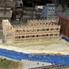
All of the drawing and design tasks are done including all the 3D printing development. I'm waiting on some specific answers from the First Build people on the actual, exact thicknesses of their available stock and the detailed program specs on their laser cutter software. My previous suppliers used line thickness in the Coreldraw drawings to determine if it was cut or engraved. The First Build machine uses that plus line color. I need to know what these specifics are before I can bring my drawings downtown and produce parts.

The stock thickness is necessary for the fit of the floors, roof, trusses, etc. It's nominally 1/4", but it's more like .218" or .228".

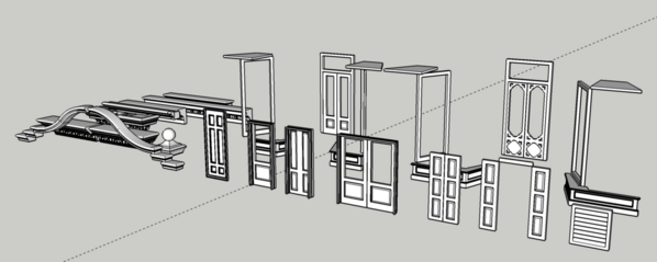
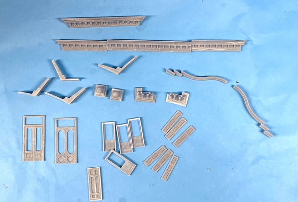
Here's the drawing showing all the pieces that are going to be 3D printed in my shop. The store show windows, while shown here, I'll probably scratch-build them out of styrene stock.

NHH 3D Printed Parts Set

The cut drawings consist of four sets based on the material thickness:

  • thick stock for walls and floors (nominal 1/4")
  • 1/8" for roof panels
  • 1/16" ply for brick overlays (pilasters, upper pediment work)
  • RC Board (a laser cut product) that self-adhesive for all windows and stone lintel and details.

Here's the thick stuff not including the floors which are boring. I need to stop, but I edit it later. Hi… I'm back… if you don't post it times out and you have to start over. It's easier to just post it and go back and edit.

Here's the thick stuff:

Placing the bricks is simply complex (or complex, but simple). I start with a couple of rows of bricks consisting of a few long mortar lines and short brick lines. I then copy and paste this once, then select both and copy and paste again. Then I select all of this and do it again. Then I select and paste downwards. So in a matter of a few minutes I go from twenty or thirty lines to 35,000 lines. In this project the real brickwork had a bonding layer every 10 courses. I used my Bronx Victorian brick work as a starting point so even that didn't need to be reinvented.

NHH Heavy Stock 1

That's the simple part! The complex part is when I "Power Clip Inside" the building outline all the bricks. This is down with a copy and then a click inside the object and POOF! the bricks are nicely inside the image. If I was just doing a drawing for drawing's sake, I would be done. But I'm not! The laser cutter cuts on .3 pt lines and engraves on .7 Pt. lines. So any place that a brick line interferes with a cut line, the cutting would cease and it would be engraved instead. So I have to go through the entire drawing and find any of these overlaps and edit the bricks to clear the cut line from any interference. This is done with the "EDIT POWER CLIP CONTENTS" choice. It's not difficult, but it is painstaking and time consuming.

NHH Heavy Stock 2

There are two more pages, but they're just inside floors and are boring.

NHH Heavy Stock 3

Here's the ply parts. These represent all the interesting brick overlays. The pilasters are four layers to set up that brick stair-step pattern from bottom to top of the openings. I have a set of doors and shutters for cutting as a back up. I'm also 3D printing all of them to make the relief panels in 3D. They're my provisional parts. I'm also printing doubles of the long brick dentil molding and pediment overlays just in case. I'm not paying by the cut. At First Build, it's a flat fee for the machine and you pay for materials. More parts in this case does NOT equate to more material, just more cutting time.

NHH 1:16 Ply Parts

The next batch are the RC Board self-adhesive parts. I always cut extras of these since they can break during fret removal and assembly. I use clear styrene for glazing.

NHH RC Board Parts 1

The little gaps you see are put in after the parts are drawn. They are tabs that hold the cut parts in place during cutting and handling. I've learned to put the notches in very quickly since I've now draw SOOOOO many windows.

NHH RC Board Parts 2NHH RC Board Parts 3

Once I find out those specs, I'll put the final touches on parts affected by the thickness and start producing parts. Meanwhile, work continues apace on the helicopter.

Stay tuned...

Attachments

Images (8)
  • NHH 3D Printed Parts Set
  • NHH Heavy Stock 1
  • NHH Heavy Stock 2
  • NHH Heavy Stock 3
  • NHH 1:16 Ply Parts
  • NHH RC Board Parts 1
  • NHH RC Board Parts 2
  • NHH RC Board Parts 3
Last edited by Trainman2001

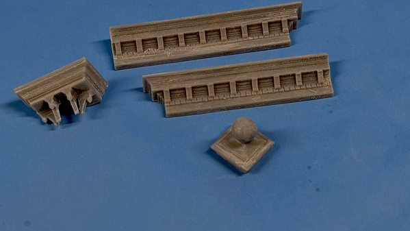
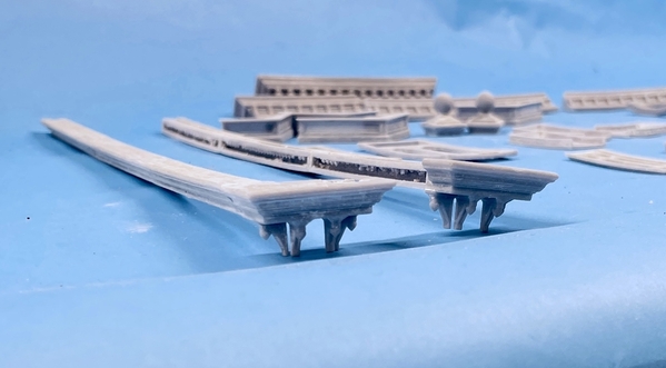
Two things happened today! First I got the first successful prints off the machine. The lower cornice that goes over the store fronts is three-parts due to the small capacity of my Elegoo Mars printer. I printed the two ends and they came out great. The other print was 50/50. One corner cornice with corbels came out perfectly. It's mate failed to actualize. The other was one of the caps of the corner towers. It too was perfect and its mate failed mid-print. I've surmised that either the surface grip on the left side of the Fulament build plate was less than the right and/or the bed may not have been level. I leveled it and gave the build surface a light sanding to break any glaze that formed.

NHH First Prints

The coolest thing was I drew the cornice's corbels to be open on their inside and the printer reproduced that exactly.

NHH First Print CU

The second good thing that happened was getting the data I needed on the laser cutting. I took my grandson to the airport (he's going skiing with his other grandfather in California) and then stopped 1st Build to see if they were open, and, if so, that I could get some stock measurements and the laser cutting parameters. They were open. Not only did I get the data I wanted there, but I was able to go on the Web and find the operator's manual for their laser. I'm going to learn it before I go and cut anything.

It's really reasonable. The ply I'm going to use is $1.30/Ft sq. My material costs will be well under $100. And it costs $2.00 per job which equates to about two bucks for each sheet I cut. I have 10 sheets total so my cutting costs will be $20. Any way you cut it, it's a good deal. I'll probably have to make a couple of trips since their only open to the public for a couple of hours per day.

This is the laser. They have two and their big.

1B Laser 1

This is the cutting sample you can use to determine the speed and power. I think 100% power and between 50% and 70% speed.

For cutting the 1/8" (.200") ply 100% power and 2.% speed and 300 PPI (pulses per inch).

1B Lasser Settings

Stay tuned. Things are going to get good.

Attachments

Images (4)
  • NHH First Prints
  • NHH First Print CU
  • 1B Laser 1
  • 1B Lasser Settings

Thanks Mark! But wait… there's more!

More 3D printing success. I was having failures only on the left side of the build plate. That could be a leveling problem, so I re-leveled the build plate and re-sanded its surface to give it more tooth. This did the trick. All the prints since then have been perfect with no separation from the plate. I printed the long center section of the store front cornice, the serpentine molding that tops the pediment brick work, and the complex 2-part top cornice that sits on the pediment. The last thing that came off the machine is the left storefront door, the mid-door and one of the four pieces of the store window bases. I didn't take a pic of that last one… it's still hanging on the machine.

NHH Store Front Cornice

This one printed beautifully right on the plate with no supports. It had a solid back and no overhangs that needed any supports. These are attached to the Fulament removable, flexible build plate. It sticks to the machine with a broad 3M adhesive magnet sheet that firmly attached to the existing aluminum plate on the machine. You just pop it off, bend it, and the parts detach. Small parts don't break loose so I use a razor scraper to remove them.

NHH Upper Trim Success

This part gets joined in the middle to make one large part. Can you imagine making this part "old school"? I wouldn't no where to start. By being able to draw it in SketchUp, the curves are all true ogee, the corbels actually have roundels on the flanks that reproduced correctly. With this complexity, I probably wouldn't even consider building it at all.

NHH Top Pediment

The architectural parts printing is going faster than I expected. I'm doing two to three loads a day with the printer running all night. Unlike a string printer, when this little guy is lined out, you can leave it alone and it just does its thing. It's always exciting coming down in the morning and seeing some nice new parts hanging there waiting for you.

I will probably do the laser cutting early next year after the holidays. I woke up thinking about the changes I need to make on the laser drawings now that I know the true thicknesses. I might go the same way I did with the Woodbourne Gallery; beveling the corners so the brick lines would line up correctly in the corners. This makes building harder, but it looks pretty good. I kept the 45° sanding fixture so there's that. I'm wondering if I can use it in conjunction with my 4" belt sander. I could rough the bevel on the belt sander and do the finish work with the bevel fixture and a piece of sand paper attached to my granite surface plate as I did the last time.

Attachments

Images (3)
  • NHH Store Front Cornice
  • NHH Upper Trim Success
  • NHH Top Pediment

Thanks guys! I just noticed… this thread has reached the 100 page milestone.

The printer is running full out and producing parts without defect. The fixes I did (leveling and sanding the build plate) solved the adhesion issue. It printed all last night, then another load this morning and lastly one finished this evening. At this rate, all the parts prints will be done next week. That said, if I do any interior stuff and don't just use photos, then printing will continue. I'm designing the build so the interior will be reachable even when finished.

Here's more parts. They're sanded and post-cured. After the pic added some filler to the top cornice joint. It will be almost invisible. The single upper-story back doors are hanging on the machine now and are perfect. I still have the long eaves cornice (6 parts) and reprinting the corner cornice and ball tower that failed earlier, and the lower back doors and the shutters. Lastly I have the right main door and three more store front bases.

NHH Print Progress

I bought a piece of 1/16 ply at the hobby shop for those laser print parts.

I decided to use the mitered corner method and changed the CorelDraw laser drawings to reflect this and I also adjust any lengths affected by the thinner wall thickness. I'm not changing the floor sizes since I want some play in them. I'm going to make it so the floors load from the bottom. I drew some roof trusses that will also be cut out of the thick stock. I had room on the sheet so it won't add any cost, just a little more cutting time.\

For any of you who have access to SketchUp, I've just uploaded this model into their 3D Warehouse. It's the complete file and is in full-scale size. All my SU drawings are done in 1:1 scale and then scaled when I either load parts into CorelDraw or shrunk to make 3D parts STL files. Most of my other notable projects are on the warehouse also.

Attachments

Images (1)
  • NHH Print Progress
Last edited by Trainman2001

More printing and a few more problems. Sometimes things fail with no apparent reason. I'm almost done the printing part of the job (exterior only). I was going to take more pictures of the interior when me made our New Years trip back East, but we cancelled due to the increased COVID risk. It wasn't just the risk. It was the insecurity of the trip itself. What would be open? Hotels, etc. I may ask the proprietor to take the pictures for me.

I have 10 shutters printed and need 10. There's one window that has the shutters closed making 12, but the closed back is just flat so I can use styrene for that one. So that's done. All that's left is the long cornice running front to back on both sides. I'm printing that in 6 pieces. I changed the FEP recently, but it's been sticky in some places. Here's an example.

This was yesterday's second shutter run. I re-designed the support scheme since the supports failed on two on the previous run. In this case here's what happened. This is the job hanging upside down right on the machine. It's on my removable, flexible build plate. Four printed perfectly. One has only a base without supports, and the other has nothing… nada… bupkis! What's missing is a blob stuck to the teflon at the bottom of the vat. It means removing the vat, emptying the content through a fine-filter funnel into a bottle, cleaning the resin and somehow removing the remnants without destroying the FEP in the process and putting it all back together. All in all it kills 15 minutes. And I don't like doing it.

NHH A Print Mess

So here's current production without the four shutters not yet off the machine and the long cornice parts.

SHH Even more prints

Attachments

Images (2)
  • NHH A Print Mess
  • SHH Even more prints

That could work! Apparently, there is a "Clean Vat" selection on the Elegoo Mars. I will try it the next time it happens. This time, I popped off the pieces using a very carefully applied razor scraper. But the FEP was already damaged so I replaced it. I also did some more research on adhesion issues and, based on what I found, reduced the number of layers on the raft level while increasing the exposure time of same. I also changed the geometry settings for the raft. The changes worked perfectly and I printed 6 pieces of long wall cornice in two 3-piece batches.

I cleaned these parts along with the remaining shutters. I then glued all the long cornice pieces together so they're done except for a final wash and painting. To that end, all the 3D printed exterior details are completed. I'm holding off going down to U of L to do the laser cutting until this Omicron spike burns itself out. It was a good decision staying put during the holidays. It was low-stress for us and we're still well as of this moment.

Here's the long wall cornices all glued up. They're bit warped, but my resin mix has some give in it and I will make sure it's straight when glued on the wall.

NHH Long Wall Conices

I also glued the over-the-store cornice together so all of them are in their final form. Here's all the parts waiting for further processing. The way these parts are sitting there kind of shows the over foot print of the future building with the over-the-store cornice being almost the full width and the long cornice giving the depth.

NHH Ext Parts Complete

I will do a final clean and spray the parts with primer. I can also paint the colored parts at this time. Meanwhile, work continues on the Seahawk and I have another building to construct, the Korber Power and Light Office building that I got in trade for some 3D printing I did. It's a 6-story office building that I'm going to build for the open space between the tracks in back. I'll rename it "Pennsylvania & Pacific RR" headquarters building.

Attachments

Images (2)
  • NHH Long Wall Conices
  • NHH Ext Parts Complete

Been a while since I posted due to:

A) working feverishly to complete the Kitty Hawk 1:35 Seahawk SH-60B model. I posted this blow-by-blow on four plastic model forums and was able to detail it beyond my imagination because one of the readers is a Seahawk Naval pilot.

B) U of L's Makery was closed to the public due to COVID. It finally opened again this week and I am ready to laser cut all the parts for the Hardware store project. And when I do, all y'all will be privy to the agony and ecstasy of the build.

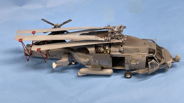
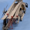
Here's the Seahawk: This, believe it or not, was the most challenging model aircraft I've ever tackled. This was based on several factors. The Kitty Hawk instructions were ambiguous sometimes and missing things other times. The styrene was somewhat brittle and broke at the worst possible times requiring drilling tiny holes and pinning things with Phosphor-bronze wires. The ResKit add-ons (Main Rotor, Tail Rotor, starboard side GE T700 turbo-shaft engine and the detailed swinging tail boom hinge area) added immense complexity both in building them outright and integrating them with the existing plastic parts. Lastly, making it in the stored position was a huge change. Interestingly, folding the rotors and tail boom in real life are also a big pain in the butt requiring lots of steps, even though the blades are folded by remote control. What struck me throughout was just how much more complex the naval version of the machine versus the Army Blackhawk on which its based. The "B" model is obsolete. The newer versions do not use the sonobuoys that are ejected from the dispensers you see in the first image below. They now use towed dipping sonar for this purpose. The model has a complete interior including the sonarman's console and the ejector rack.

SH-60B Final Port 3SH-60B Final Port Side 2SH-60B Final 3-4 ViewSH-60B Final NoseSH-60B Overhead

The braces that hold the folded blades broke at least three times.

SH-60B Final OverheadSH-60B Final Strbd TopSH-60B Final Strbd Side

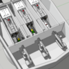
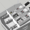
Another project is consuming me is building the Missouri turret offered by Takom with a full interior extending down into the barbette. The model is just an empty box. I'm drawing all of the machinery inside and it's the most challenging SketchUp project I've ever attempted on many levels. Just finding out how big things are and how they relate to each other is a big jigsaw puzzle. Here's what I've done so far. Remember: the externals will be in the kit, everything else will be 3D printed or scratch-built in some combination.

Screen Shot 2022-02-10 at 7.48.06 PMScreen Shot 2022-02-10 at 7.52.17 PM

Mo Gun~~ 2022-02-09 15480300000

I have a puzzle to solve. Perhaps one of you guys has the answer. There are 8 compartments in the turret forward part: 1 on each side housing the manual aiming stations, 3 gun rooms and 3 compartments that lie between the guns where the powder hoist operator sits. But… there are only 6 doors/hatches in the rear bulkhead wall. So… how do the guys get into two of the gun rooms?

16 inch Gun House Looking Fwd

The two smaller doors left of center and the to right of center are the entrances to the powder hoist control area. The two doors at the extremes go to the manual aiming stations. The center larger door goes to the center gun room. So… how do you enter the left and right ones? I'm working with the curator of the USS New Jersey battleship museum and am going to ask him. He's committed to having the model displayed there when it's done.

Till next time.

Attachments

Images (12)
  • SH-60B Final Port 3
  • SH-60B Final Port Side 2
  • SH-60B Final 3-4 View
  • SH-60B Final Nose
  • SH-60B Overhead
  • SH-60B Final Overhead
  • SH-60B Final Strbd Top
  • SH-60B Final Strbd Side
  • Screen Shot 2022-02-10 at 7.48.06 PM
  • Screen Shot 2022-02-10 at 7.52.17 PM
  • Mo Gun~~ 2022-02-09 15480300000
  • 16 inch Gun House Looking Fwd

Myles, I knew you were still with us since I saw a few posts of the Seahawk build over the last while on Facebook.  It does look extremely complex and delicate as you told us.  Superb looking.

I'm glad the Covid restriction has been lifted so you can get in and get the parts for the hardware house cut soon.  We are here when you get started.  Welcome back!

Glad to please Mark!

I got the answer to my question from Ryan the curator of the USS NJ museum. The two side gun rooms are open on their outer flank. The doors at the end of the bulkhead lead to them AND to another compartment more forward which houses the manual aiming stations. It was hard to see this on the floor plan drawing I have. I think I'm going to do the landscaping on the Rick house site today…. finally! I've had the tracks near it covered in masking tape for months and want to run some trains.

Actually worked on train stuff today. Several things. First I repaired the nickel silver trim on the front of my 3rd Rail Pennsy S-1. This appliqué had broken loose before and I tried fixing it through non-solder means. It didn't hold. I ground away the surface to get new brass, clamped the very-springy piece back into position and soldered it with the RSU. I then found a brand-new bottle of acrylic Pennsy Brunswick green, masked the trim and air brushed to finish it.

Pennsy S-1 Trim Solder

I then backfilled the foundation area on the rick house in preparation for ground cover. I again use Sculptamold mixed with some W-S earth tint. I dampened the dry STM so the new wouldn't have all it's moisture sucked out before it set. I had previously wrapped the entire building base with Press n'Seal to I wouldn't get wrecked during the landscaping activity.

RH Back Fill

Lastly, I was given a Korber kit in payment for some of the 3D printing I did for a friend at the hobby shop. It's their General Power and Light office building.

P&PRR Office Box

I'm going to make it the Pennsylvania and Pacific Railroad's main office with appropriate signage on the roof. It's not a particularly sophisticated kit, and I'm using it as a time-filler until I get all the stuff done for the hardware store. I needed to pick a spot for it. There are three possibles.

P&PRR Office Loc 1P&PRR Office Loc 2P&PRR Office Loc 3

The walls are a tad warped and I'm reinforcing them with some serious Plastruct "steel".

P&PRR Office Straighening

Till next time.

Attachments

Images (7)
  • Pennsy S-1 Trim Solder
  • RH Back Fill
  • P&PRR Office Loc 1
  • P&PRR Office Loc 2
  • P&PRR Office Loc 3
  • P&PRR Office Box
  • P&PRR Office Straighening

You are absolutely right. My first bought was to put in the space between the tracks in the back. that's where it will go. It will need an access road, and instead of running the road across a series of switches all set at an oblique angle to the proposed road, I think I'll just cut a highway tunnel under the high line and make a short road with a nice 90 degree RR crossing over a single track. having the RR's main office between the rails makes sense in a "model railroading" sort of way.

On second look, I may not have to do the tunnel. It's only one oblique track that needs a grade crossing. I can bend the road so it comes in at a more 90 degree angle (like prototype RRs do) so the crossing will look more natural.

I got the ground cover on the Rick House site yesterday. I used some beigey paint that I had mixed for a wall repair. It was a light earth color. I then sprinkled a mix of W-S brown fine ballast and light turf, giving a less brown raw dirt look.

RH Ground Cover 1

After pulling all the tape this is what it looked like. Not too bad. Some STM needed trimming where is bled under the building when being applied.

RH Ground Cover 2

It needs some TLC on the slopes near the tracks such as some weeds and long grass. I can add most of this from the aisle edge of the layout. The area near the street can only be reached by scooting under the layout and coming up in the open space between the bridges.

An aside: My physical in November had my weight up to 184, my blood sugar at 104 for the first time in my life, so my internist suggested that I lose some weight. He said, maybe 175 was a good weight for me. I didn't like my weight! Clothes weren't fitting anymore and it was just unhealthy. I went on my kind of diet. I analyzed what I was doing differently that added the weight. When we moved to Louisville in 2009 I was at 193. I was FAT! It was years of business travel and lunches in the corporate cafeteria, plus, plus… I went on a diet and went down to 175. It held for a while, but over the last four years, it was just creeping up. Every trip back East added 3-4 pounds, and I'd lose two, and there as a new set point. It was caused by these factors: portion size, seconds, too many little deserts, more wine, and more lunch than I needed.

So without changing WHAT I ate, I adjusted how much I ate. I reduced my portion size about 30%, cut out seconds, stopped eating carbs at lunch, limited my wine to one modest glass, and have much, much less desert. I'm now at 174 and I want to go further. I'm technically overweight by the BMI until 169. I haven't weighed 169 since the early 80s. I'd be happy at the low 170s.

So why am I wasting your time with this drivel? Here's why! I was dreading going under and on top of the layout because it was getting harder to do. I thought it was my AGE. It wasn't! It was that extra 10 pounds around my waste. Yesterday, getting under by sitting on my scooter and climbing up to layout height was easy. It felt really good! Another benefit. I just put my belt on the fourth hole holding up my jeans. I've never had that belt on that hole since I bought it years ago. It had gone from the 3rd hole to the 2nd which was the wrong direction. It's now going in the right direction. I still exercise regularly on the recumbent bike and elliptical. So eat less move more! A diet plan in one sentence. I have not changed what I eat. I was already eating pretty healthy, but I reduced how much of it goes in. It's chemistry.

Now, back to the Rick house.

I put the building back in its slot. Needed some adjustment, but not bad from the viewer's side of the layout.

RH Ground Cover Fin 1

It needed some added STM around the loading dock and the rear facing the fire house.

RH Ground Cover Fillin 1RH Ground Cover Fillin 2

There is a problem! When I checked out the street side, the building is not sitting down to ground level and I'm not sure why.

RH Ground Cover Problem

You can see it  looking up the street from the layout's front, but not easily. Not sure what to do about this. I'm going to wait until the newly applied STM is cured, pull the building and see if I can find what's lift it. Stay tuned.

I'm debating building a chain link fence to surround the construction site. Not sure if it will add or detract from the scene. I have a the big billboard to install and will put a light on it. I also need to add some wood piles, and make a batch to hang from the crane's hook. I have to add some construction workers around the site to liven it up. End is in sight.


The

Attachments

Images (6)
  • RH Ground Cover 1
  • RH Ground Cover 2
  • RH Ground Cover Fin 1
  • RH Ground Cover Fillin 1
  • RH Ground Cover Fillin 2
  • RH Ground Cover Problem

Myles, the 90 degree turn in the road sounds good.  You are right, it is quite common near railroads.  I occasionally drive through an area that has two 90 degree turns, between two railroads with a grade crossing over one and a one lane underpass onset the other.  There is a bridge over the creek that flows between the two tracks that the road parallels for 100 feet. It would be a neat scene to model.

Congratulations on the weight loss.  My story is similar, and I am 10 to 15 pounds over where I was 10 years ago when I lost 35 pounds.  I have been working on more exercise and less food.

Mark, we all know that losing isn't really the battle. It's keeping it off. The percentage of people who maintain their weight is quite small. The problem with reducing intake is you're no longer as satisfied (full) as you used to be so you add a little here and there and Poof! you up 10 pounds. We have a dear friend who is very, very overweight. It's affecting her health with orthopedic breakdown. She needs to lose 100 pounds. It seems so daunting, but I would be if she reduced her intake by 20% a day, she'd slowly start to lose. It would take a couple of years. Her weight prevents her from exercising which creates a vicious circle. Move more eat less. If you can't move more then you even have to less than less.

I got rick house to settle down more so the gaps on the street side are now decent. I touched up some of the areas missing ground cover, planted the sign and brought in the rental crane. Those deals are expensive so you have to keep them working. Still have more details to add which I will be doing from time to time. Forgive the soft focus...

RH Getting There

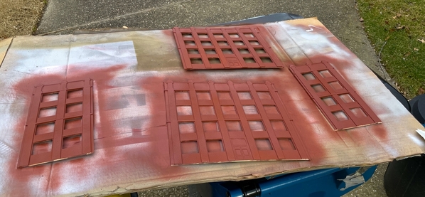
I did more work on the P&PRR office building. You have to file off all the flash on the resin casting. I also had to re-scribe the end bricks on the big walls since these are on the outside of the corner joint and show up. I'm going to 3D print a sign to go over the front door. I took it outside and repainted the walls since the cleanup exposed a lot of bare resin on the various edges. I use my go-to Rust Oleum Red Oxide Primer. I still have to grout all the brick lines. The weather was great today for an outside spray activity with a light breeze and 66 degree temp.

P&PRR Ofc Paint

The brick lines on the end were very shallow to start with so I used a triangular diamond-coated needle file to rebuild them.

P&PRR Ofc Scribing Bricks

Attachments

Images (3)
  • RH Getting There
  • P&PRR Ofc Paint
  • P&PRR Ofc Scribing Bricks

@Former Member  Just found this post. Work looks good. I have the Korber building and have thought about putting it together. For sure on my next layout, but mine has a lot of warp to the walls. Did you heat it up to flatten out or just use backers to straighten the walls. I also have the lack of brick lines in places and will probably have to file the ends out like you are doing.

Oops - just saw the I-beams you are using to flatten the walls.

Last edited by ScoutingDad

Yes! I’m going to put lumber stacks and make a sling of some and hang it in the hook. Got some construction guys to decorate the place. Still on the fence ( no pun intended) about making chain link for the site. The figures were intended for the machine shop and would have needed repainting. Since they’re actually supposed to be construction workers I can use as is.

and yes! As you saw, using stiffeners to straighten walls. Adding a bases plate between the walls and a Masonite (instead of cardboard) roof will help also. Maybe a floor or two as well.

Yesterday's work...
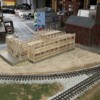
prepped the walls by scribing where the joints would fall and where all the reinforcing 1/4" wood would go, and scraped off the paint so the CA would be sticking to resin and not paint which isn't so hot. I glued the roof ledges on, more stiffeners to take out the remaining warpage, and started gluing the sides together.

I marked a place for a first floor plate too. This was to take out the warp and provide a light block so I can illuminate the lobby floor independently from the rest of the building. I'm going to selectively block out various windows so it's not just a four-story building with all the lights on. I'm going to use some strip LEDS that I bought last year for this job.

I have an ancient Dunlap picture framing clamps that was my dad's that held the bottom corner square and a corner clamp that held the top, and then used various quickie clamps to squeeze the remaining joint into contact. I pushed and pulled the mating edges so they were in perfect alignment before applying any thin CA. I pretreated the area with CA Accelerator so it would cure quickly.

I glued the opposing corners together. Next session I will glue the adjacent sides together forming the full building.

Joint areas prepped for gluing;P&PRR Prep Walls for Braces

Adding the 1st floor ledge again using some serious Plastruct H-beam that will serve double-duty: straightening a warp and providing a place for the floor plate to sit. I glued the roof ledges in before joining the walls, but held off adding the corner reinforcement until after they were joined. I couldn't be certain of how the corner joint was going to fall if I glued the blocking in early. After gluing the corners I added the blocking with more CA.

P&PRR More Bracing

The two wall sets are ready for glue up on Monday. Adding floors also helps remove any additional warpage.

P&PRR Wall Progress

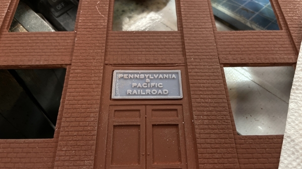
I 3D printed a raised-letter plaque for over the front doors. It fits into the recess that already molded in. Being so thin it only took 17 minutes to print. If I upgrade my Elegoo Mars original to the new Mars 3, I could print in 4 minutes.

P&PRR 3D Printed Sign

First coat was some Pennsy Tuscan red. I will go over all the raised areas with gold. I have a gold Sharpie marker that should pick out the raised areas pretty well. I may have to pre-coat with clear lacquer so the alcohol-based marker won't dissolve the acrylic base paint. Took 10 minutes to draw this on SketchUp.

P&PRR Signs Painted

Attachments

Images (5)
  • P&PRR Prep Walls for Braces
  • P&PRR More Bracing
  • P&PRR Wall Progress
  • P&PRR 3D Printed Sign
  • P&PRR Signs Painted

Work continues on the P&PRR HQ building. Got the rest of the floor ledges installed, cut the various plates for the floors, etc., and put the lighting together. As complex as my other projects have been, this one is pretty simple with very few embellishments. I may spend some time on the roof and some big signage, but that's all post-building.

The kit's roof plate is a piece of cardboard. I don't like that. I'm making it out of Masonite along with the base plate and the 2nd floor. This is the bottom. I have trouble cutting nice square pieces of sheet stock because I don't have a table saw and am too lazy to set up fences and use my circular saw. I laid out the lines and cut it with the saber saw. Unfortunately, the edge that I was measuring from (which I assumed was square) was not square so I have to so some creative sanding on the belt sander to make it reasonable. The bottom plate came out really well.

P&PRR HQ Bottom Plate

The building was not yet glued together in the above.

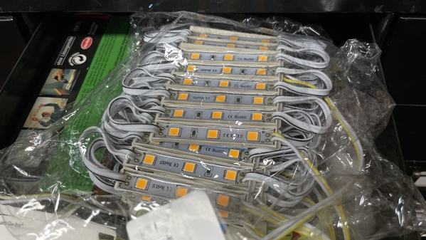
For Lighting, again, I'm going easy. I have these sheets of 12VDC LED lights that I get from Amazon that are used to light outdoor signage. They're in series and need no current adjustment. Just pump 12VDC into them. They're very cheap. The already have double-sides foam tape on their backs so mounting is a snap.

These put out a very yellow light. I bought them as "Warm White", but they look really warm to me. I don't care. It will resemble lighting in an old incandescent office building like back in the day. The yellow lead is +.

Lotsa Lights

After soldering I use some shrink tubing to protect the connections. I'm using some old light-gauge zip-cord that's really old. The copper is degraded and took a longer time than normal to tin. Most folks don't know this, but copper conductors can oxidize even inside the insulation jacket. The jackets are gas permeable over time. Silicon insulation is better, but vinyl/rubber doesn't hold up forever.

P&PRR Light Build

Here's what the light looks like on the first floor test.

P&PRR HQ Light Test 1

And here's the lights looking directly at them.

P&PRR HQ Light Test 2

At the end of the session I got the building glued together. I also painted the text on the raised letting signage for the front door. Next up is building all those window sets.

IMG_1609 2

Attachments

Images (6)
  • P&PRR HQ Bottom Plate
  • Lotsa Lights
  • P&PRR Light Build
  • P&PRR HQ Light Test 1
  • P&PRR HQ Light Test 2
  • IMG_1609 2

In a shortened session, I did get started on building up all the windows. They are installed as assembled pairs.

Here's what it looked like at the start.

There was a little flash on the upper edge on about 50% of the plastic (Grandt Line?) parts.

P&PRR HQ Windows to Build

To build the double window, first I had to remove the little bit of window sill on the mating surfaces. I cut them off with the #11 blade and then sanded them square on the precision Sander. I chose to do this one assembly at a time to avoid more boredom. It's an assembly line kind of job and not very creative.

P&PRR HQ Window Mod

Progress at the end of the session. I will probably finish this today. I use the steel weights to hold the assembled frames flat while they cure. All of these will be painted and glazed BEFORE installing in the building. When the frames are done and while the paint is drying I'll be applying the grouting to the brick work. Some of the windows will be randomly blacked-out so it looks like some are at work and some are not. (maybe working virtually due to COVID ). I'm assembling the frames on the bare Corian which is dead flat and unaffected by the solvent cement. My cutting pad's getting a bit worn and has all kind of lumps stuck to it making it no longer flat.

P&PRR HQ Window WIP

Attachments

Images (3)
  • P&PRR HQ Windows to Build
  • P&PRR HQ Window Mod
  • P&PRR HQ Window WIP

There are 54 of them to be exact at 110 singles. There are exactly the right amount which is troubling because one of them was molded funny and I would have tossed it, but I need it. Any funky windows (for whatever reason) will be on the back wall facing nobody. I made a big dent today, again having a late start because of running errands and quitting early since it was "Cocktails Friday". My wife and I established this tradition during COVID lockdown when I learned to make a mean Vodka Gimlet, Lemon drop martini and a great Old Fashioned. Couldn't go the bar so I brought the bar home.

P&PRR HQ Windows Almost there

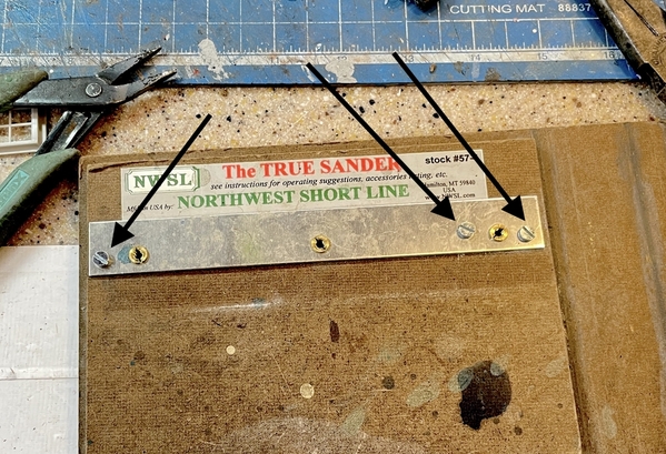
During today's work I had to do a repair to my True Sander. Fighting the thumb screws were pulling the permanently mounted fence upward. This created a gap under which the movable fence was moving putting it out of square. I couldn't tighten the screws any more and tightening them was the cause of the problem in the first place. I drilled and put in three metric machine screws, nuts and washers pulling the bar down tight and in the right place. I had to counter-bore the back since a) my screws weren't very long and b) they needed to be recessed anyway.

True Sander FIxTrue Sander Fix 2

This finally fixed an annoying defect in this product. This is my 2nd True Sander, but the first one didn't have this problem.

Everyone have a nice weekend. The temp in Louisville is going to go to almost 80. We'll pay for that. I can imagine some significant weather as a result.

Attachments

Images (3)
  • P&PRR HQ Windows Almost there
  • True Sander FIx
  • True Sander Fix 2

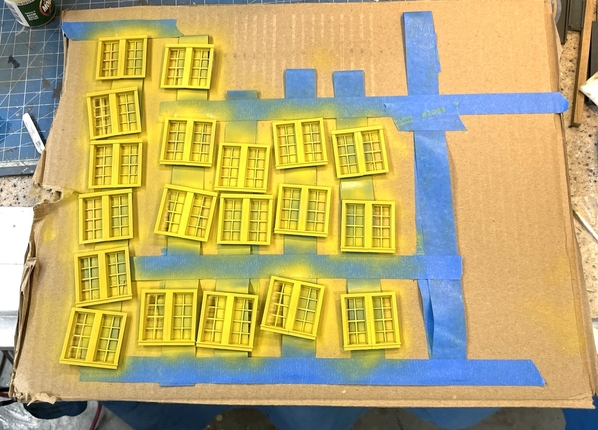
All the windows are assembled and painted. I used Badger Model Tech paint UP Armor Yellow in keeping with the overall theme of the RR. I stuck them all to some corrugated and used the airbrush. Took two coats. We're going on a two-day trip to Champagne IL to visit #1 grandson at U of IL and will be back in the shop on Thursday.

P&PRR HQ Windows Paint 2P&PRR HQ Windows Paint 1

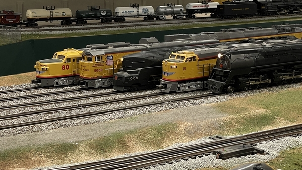
I took a beauty shot of some equipment in preparation to make the billboard.

P&PRR HQ BillBoard Shot 1

I removed the Background to enable me to substitute something.

P&PRR HQ BillBoard Shot 1

Attachments

Images (4)
  • P&PRR HQ Windows Paint 2
  • P&PRR HQ Windows Paint 1
  • P&PRR HQ BillBoard Shot 1
  • P&PRR HQ BillBoard Shot 1

It took over an hour to pose them. Some of them haven't been run in over a year. I had to replace three traction tires, use contact cleaner on the rollers and clean some track. Then I had to jostle them around to free up track. I only had to carry two of them. O'gauge trains are more forgiving regarding dirty track than our DC operating brethren, but there is a limit.

Back from visiting U of IL's campus and grandson. It's a vast place like Michigan State's is. All these land grant colleges tend to have enormous campuses. The engineering campus alone was bigger than most smaller colleges. He's doing quite well and has a nice apartment just off campus sharing with four roommates. It's in a high rise, is a two-story affair with two bedrooms downstairs and two up. Each has their own bathroom. Not like it was in the old days. Nothing on a college campuses today was like it was in the old days. They're pampered! His building has a gym, pool tables, movie theater and a BOWLING ALLEY (two lanes to be exact). Yeah! That's just like it was when I went to MSU… not!

Last edited by Trainman2001

Back to work. I got to exercising a bit earlier today which gave me a full work session too. Got the windows glazed. The kit came with 6 sheets of acetate that needed slicing and dicing. I measured the assembled frame and used the digital caliper as a marking gauge. I cut the long strips with a #11 and long steel rule.

P&PRR HQ Acetate Strips

The glazing pieces were square so I set up the Chopper 2 for the short side cuts. I wanted to gang cut them five at a time, but the Masonite Chopper base is bowed downward, so the middle strips were moving all over the place. I added a piece of illustration board to the fence's underside thinking it would fill the gap better, but it didn't work well. I ended up cutting two at time holding the strips on each end. I also found that the left side barrier is no longer square to the cutting clamp while the is okay. I'm making sure to put the sliding fence at that edge.

I cut a lot of these suckers.

P&PRR HQ Window Panes

I used MicroMark Pressure Sensitive Adhesive (PSA) to secure the glazing to the frames. I talked about this stuff before, but it's so useful in these applications that it's worth repeating it. It's water-soluble when liquid, but when cured really only comes off with Goo Gone. It dries clear, tends to stay where you put it, and lets you glue glazing in with very little fuss. It does not cloud or attach styrene or acetate. It works best when the liquid dries and loses any white color. Once it's clear you're ready to go.

I put a thin film on the glazing surfaces on the frames doing them five at a time. By the time I coated the last piece, the first was ready for the acetate. In this example you can still see some white liquid indicating it's not quite ready for the glazing. I you glaze too soon, you run the risk of the adhesive to ooze out onto the viewing surface and it's not as strong.

P&PRR HQ PSA on Frames

Here are all the windows with glazing. A ton of windows. I'm glad the building wasn't any deeper or taller. It gets boring...

P&PRR HQ Windows Glazed

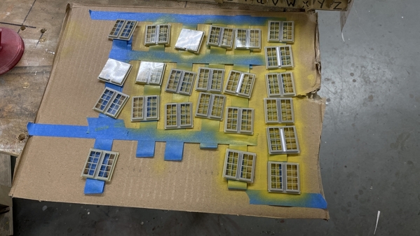
I'm going to airbrush the inside of the glazing with some flat clear so they're opaque. I'm not planning on doing any interior details since it's 12 feet from the viewer, so frosted windows are called for. I'll do that tomorrow. I used the same taped boards to re-attach the windows for the flat coat. The white styrene strips in some of the frames serve to reinforce questionable joints and help to flatten some that had too much bend when they cured.

P&PRR HQ Ready for Flat Spray

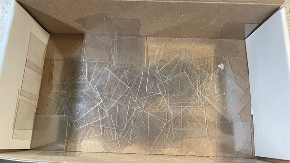
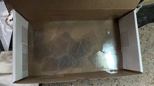
I didn't need all the glazing that I cut. Here's what was left over (enough for another building it looks like).

P&PRR HQ Glazing Surplus

I didn't toss these. Acetate is hard to come by and you can always find a use for more window glazing.

Till next time.

Attachments

Images (6)
  • P&PRR HQ Acetate Strips
  • P&PRR HQ Window Panes
  • P&PRR HQ PSA on Frames
  • P&PRR HQ Windows Glazed
  • P&PRR HQ Ready for Flat Spray
  • P&PRR HQ Glazing Surplus

Add Reply

Post

OGR Publishing, Inc., 1310 Eastside Centre Ct, Suite 6, Mountain Home, AR 72653
800-980-OGRR (6477)
www.ogaugerr.com

×
×
×
×
Link copied to your clipboard.
×
×