Hi folks,

I'm working on a new layout, and I'm planning to power switches from an auxiliary power source; this will be a first for me, as I've only ever powered RealTrax and Lionel Tubular Remote switches before using track power. I'm starting out with RealTrax and Lionel Tubular Remote switches again this time around and will be adding Z-Stuff motors to some Atlas and Ross switches on other parts of the layout down the road.

I understand, in principle, how auxiliary switch power works between a transformer and a single switch. But what's the best way to power multiple switches off of one transformer? Can I daisy chain the hot and common leads from switch to switch in series? Or do I need to use a terminal block and power the switches in parallel? What's the best gauge wire to use?

Also, I'll be using a Z-4000; my understanding is that I should use the 14V accessory output as opposed to the 10V. Would that be enough to power 13 RealTrax switches and 4 Lionel tubular remote switches?

Thanks guys!!

Rafi

Last edited by Rafi
Original Post

Replies sorted oldest to newest

I just finished wiring all of my switches into the control panel. I used the constant power pin for them all. 10, tubular switches, 4 O22 and 6 O72.  yes use the 14V output and run it to a terminal block and then from this block run to all your switches. sometimes the old switches like 18V but i gave mine a good cleaning and they work great at 14V.  i used 16 gauge wire, and these terminal blocks:


https://www.amazon.com/gp/prod...00?ie=UTF8&psc=1

Last edited by C_Murley

022 switches are power hogs with the original 1445 and 642 bulbs. They use up to .4 amps each with these bulbs. Highly recommended to switch to led replacements such as those offered by Town and Country Hobbies. There are other sources as well.

Both 10 and 14 volt outputs on the Z4K are limited to about 40 VA output I believe, so they will overload quickly. Dont know what the realtrax switches draw, check the specs.

Rod

Great advice, as always. Thanks guys. Good to know I can do serial or parallel (I'll likely daisy chain/serial since it'll save wire and be lower profile). Also great advice on power draw, Rod--thank you. I suspect the RealTrax switches draw a similar amount to the 022's since they're also incandescent. Thanks for the advice on LED replacements. I'll send a note to the T&C folks to see what they recommend for replacement LED's for both the 022's and possibly RealTrax.

Thanks again!!

See this recent OGR thread re T&C LED replacement for Realtrax.

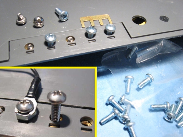
As for the daisy-chain approach, this tapping "as-you-go" is how the internally/track-powered method using the jumper-bar works!  As for low-profile daisy-chaining, it has come up before as to the short terminal screws on the switch terminals - difficult if not impossible to securely attach 2 wires.  I dug up this photo proposing using longer #4-40 machine-screw hardware bottom-up rather than top-down coming from under the layout space permitting - would allow stacking crimped terminals to effect daisy-chaining.  Not sure if this method is frowned-upon by Realtrax police?

realtrax screw terminal conundrum

Attachments

Images (1)
  • realtrax screw terminal conundrum

I used mostly single direct wiring on my track switches. My switches are Marx 1590, powered by a separate transformer and are not wired for automatic operation.  All 31 track switches were wired to a common ground.  Another wire from each track switch went to a mini push button switch on the control panel. 

A separate 5 amp 14 volt transformer supplied the power and was wired to each mini push button switch.  One wire from the transformer was sent to the control panel and short wires were run from that to each track switch mini push button switch often several can be wired in a star to close mini push button switches.  The other wire from the 14 volt transformer was wired to the common ground.

One track switch is operated at a time.  But mini push button switches can be pushed at the same time, operating in parallel. 

The are four pairs of track switches that must both be thrown as a pair for operation.  The pair are both wired to one mini push button switch for each direction and thus these two are operated in parallel.  That is the push button switch provides both track switches with 14 v and they each draw their amp or so current.  The current load on the push button switch is twice as much as it was working only one track switch.

Two of these paired track switches are shown below on the couple of switches that move a pair of track switches that allow the train to move from the inner loop to the outer loop and are shown at the bottom of the track plan control panel.  One pair of track switches in parallel is the two mini push buttons at the bottom left corner, red and green.

Train Complete 1-17-2015 152

Charlie

Last edited by Choo Choo Charlie

On 0-22, 0-72 switches, they will get U post connection from the rail. For power you will need just one wire that goes from switch to switch. If you do not use the rail as the U post return the non derailing features will not work.  Powering the switches is easy. It is the control wires that use up all the wire with two wires from each switch back to the control panel. I am not familiar with fastrack, it may be the same way. 

Just to be clear on our electrical terms here, when you "daisy-chain" the power from switch to switch, you are connecting all the hot sides together and all the ground sides together. Done this way, you will be wiring the power to your switches in PARALLEL, not SERIES.

You would never  power multiple switches and/or accessories by wiring the power to them in series. It would not work.

Last edited by Rich Melvin
@Rich Melvin posted:

Just to be clear on our electrical terms here, when you "daisy-chain" the power from switch to switch, you are connecting all the hot sides together and all the ground sides together. Done this way, you will be wiring the power to your switches in PARALLEL, not SERIES.

You would never  power multiple switches and/or accessories by wiring the power to them in series. It would not work.

I was thinking the same exact thing. I didn't say anything because I thought i was  missing something.  😀

Last edited by Rich Melvin

If you wired in series you'd have to turn one sw. on, to turn on one item, plus/or power the switch(s) next to it.  E.g. "safety lockout switches"  use series among other tricks to kill power behind certain hvac access doors.

Using a parallel daisy chain is basically mimicking a terminal block... a convenient item, not a necessity.

Mostly you only run one leg of polarity towards switches anyhow, the other bypasses most switch banks unless direction or lights on switches are involved or the latter is switched opposed for some odd reason.

Old design did a lot of switching on the "hot" wire ac/dc.  Modern electronics tend to be designed with triggers that wait for a ground (dc) to turn on, even if the "points" deliver something else.   They are just smaller switches/relays to me. 

Hi folks,

I just wanted to chime in and again thank everyone for the great suggestions and information. I'm also sorry for conflating series and parallel/daisy chaining terminology. I should have looked up the terms first to make sure my impulse was correct--a good reminder to always double-check before posting. In hindsight, I should have titled the thread "daisy chain or terminal block?"

It's been educational, regardless, however! 

Thanks again for the great info. Had I not started this thread, not only would I not have been reassured that daisy chaining would work, but I also would have probably found out the hard way that my incandescent switch lights, some of which will be a pain to access once the layout is up, would need to be converted to LED. Now I can get that all done ahead of time, thanks to this thread. 

Thanks guys!

Rafi

Add Reply

Post

OGR Publishing, Inc., 1310 Eastside Centre Ct, Suite 6, Mountain Home, AR 72653
800-980-OGRR (6477)
www.ogaugerr.com

×
×
×
×
Link copied to your clipboard.
×
×