I'm working up the courage to replace some of the incandescent  bulbs in my engines which I have upgrades to TMCC with boards from ERR. I've watched several videos on you tube, but I'm still concerned I'll fry a board or mess something up and render the engine useless.  I am planning to buy 3mm and 5mm LEDs with a positive rating of 20ma. I'm assuming the ERR board terminal for lights is 12 volts DC. According to a table on the page of the led calculator the voltage drop is between 3.0 and 3.5.  The results calculator results is showing  I need to insert a 430 ohm resistor in the circuit.

If someone would confirm the above and or correct the items which are wrong, I would appreciate it. Please remember I'm taking baby steps here, so please try to keep your responses as simple as possible.

Original Post

Replies sorted oldest to newest

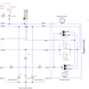
A 470 ohm resistor is a good choice for the job, you can use any value greater than the computed minimum, the LED's just won't be quite as bright.  For plain TMCC stuff, you will also need a .01uf capacitor directly across the lighting outputs of the TMCC board.  This is required to provide a load for the lighting triacs to fire.  Finally, I recommend a series diode as well in the lighting circuit, this protects the LED from reverse voltage.

Attachments

Images (1)
  • mceclip0
Last edited by gunrunnerjohn

Well John, I guess I should feel honored.  I really appreciate all your numerous contributions to the wealth of  great information on this forum.  Actually, for what it's worth, after reading many of your posts, you and others inspired me to join and also try to help answer questions here.  So what I'm saying is thank you.

To Fivenehocs, if you don't already know this: when looking at an electrical schematic diagram, where you see a diode or LED represented by a triangle pointing into a perpendicular line, that line represents the cathode/negative end of the diode/LED.   On a diode in the physical world, the stripe around it at one end is the cathode.  Similarly on an LED the lead next the flat spot on the side of the case is the cathode.  If the LED leads are uncut, its also the shorter lead.  On John's schematic you'll notice that the diode and LED both have their cathodes electrically oriented in the same direction, towards the TMCC Light Output.

I have used LEDs with many of the TMCC conversions that I have performed. I have not had good success with powering the LEDs directly from outputs 4 or 5 on the ERR board. It appeared to me that that voltage level varied too much for consistent lighting of the LED. After my initial trials I started using the small boards that ROYZ Trains provides for either single or dual light operation. The boards are about $10 and they work great. Roy is also very helpful when it comes to questions regarding the application or installation. The website is https://royztrains.com. I hope that this helps with your projects. Feel free to contact me if you have any questions.

I have installed hundreds of LED's into TMCC upgrades and existing locomotives, I've never had any issue with consistent lighting.  Here's an extreme example of what you can do with the lighting outputs of the TMCC RxLC boards.

Cruise Commander Lite Beta Test, Part Deux

BEEP TMCC Lighting

I did an RMT BEEP with the then new ERR Cruise Commander Lite board, the RailSounds Commander, and custom lighting.

This BEEP got the full treatment.  Dual directional headlights, bi-color markers, separate number board lighting, strobe light, and separate controls for the cab light.  The only limit is your imagination.

Attachments

Images (2)
  • BEEP TMCC Lighting
  • mceclip0

Thanks for the reply regarding the LEDs use with ERR boards. You are correct that LEDs can be directly powered from the ERR board. However those outputs on the ERR board were designed to power an incandescent bulb and the output is not a fixed voltage.  As shown in your diagrams you need more components than just the LED and a resistor namely you show a capacitor and an additional diode. I assume that these are to provide a capacitive load to for the board.

The board that ROYZ Trains sells has similar components and has a constant voltage output. It is also very convenient to use since one only has to connect the two wires to pins 4 and 6 or 5 and 6.

Paul, you'd have a LOT of $10 boards tied up in the lighting for the locomotive I illustrated.  While I'm sure those boards work, not everyone wants to spend that much extra money for simple wiring with five cent components.  The only caps I needed was for the blinking LED for the strobe and my custom cab light control board.  Also, the bi-color LED's might be more of a challenge with the ROYZ boards.  Finally, the bulk of multiple ROYZ boards can be an issue as well, it certainly would have been in that BEEP!  For MARS lights, I use the top notch http://www.ngineering.com MARS light simulator board, I haven't found anything that does a better simulation for anything close to the price.

One size doesn't fit all, that's all I'm saying.

Always interesting when GRJ gets in with his comments.  I'll bet his approach cost a lot more than a few 5 cent components!   Just the board production blows that way out of the water!  Besides Paul is just trying to get the job done with minimal fuss and he found a way.  Just because it isn't GRJ's approach doesn't mean there is anything wrong with it!  Especially since it worked for Paul.

@K4s-RRA posted:

Always interesting when GRJ gets in with his comments.  I'll bet his approach cost a lot more than a few 5 cent components!   Just the board production blows that way out of the water!  Besides Paul is just trying to get the job done with minimal fuss and he found a way.  Just because it isn't GRJ's approach doesn't mean there is anything wrong with it!  Especially since it worked for Paul.

Au contraire.  I don't use a board, I do indeed just solder the components together, and everything does indeed cost way less than $1.  The four components suggested for the headlight LED in any sort of quantity are less than a quarter.

Also note that we weren't addressing Paul's job, but rather suggesting approaches to the original poster.  I indeed make a comment about the boards and their costs, if you're putting a bunch of lights in, you could easily have $40-50 tied up in a few components that with a very little soldering you could have done for a couple bucks.  I don't know about you, but I think that's worth pointing out.

Add Reply

Post

OGR Publishing, Inc., 1310 Eastside Centre Ct, Suite 6, Mountain Home, AR 72653
800-980-OGRR (6477)
www.ogaugerr.com

×
×
×
×
Link copied to your clipboard.
×
×