I am converting a Lionel SD40T-2 no. 6-28255 (engine no. 4551) to TMCC using a ERR Cruse Commander 4.1 board. The SD40T-2 was conventional but has smoke, directional LED lighting and sound. I will be using the ERR Railsounds board for sound. I have wired the SD40T-2 up already and forward and reverse movement is working fine. My question is can I use the existing light system with the ERR board. The ERR board has only a one wire input for front light in, rear light in and common. The light system has three wires going to both the front and rear PCB light boards. The wires are as follows:

Front Lights:

Brown wire w/black stripe

Solid Brown wire

Black wire w/white stripe

Rear Lights:

Brown wire w/black stripe

Brown wire w/red stripe

Black wire w white stripe

I am not that technical when it comes to circuitry, so please be kind with your replies and keep it simple if you can.

Thanks,

Ed Kempf


Last edited by ehkempf
Original Post

Replies sorted oldest to newest

Yes, but you need to see specifically what they have going on at the PCB for the lights.  Typically, three wires because one set is the Head lights, but another is a jumper to run the rear marker as red when in forward, and vice versa when in reverse.  Front markers come on in Reverse.

Or it could be a different scheme.  How did the lights work before conversion?

It can be done, with a current limiting resistor, but you will need to get into the details of what is on the PCB.  G

GGG posted:

Yes, but you need to see specifically what they have going on at the PCB for the lights.  Typically, three wires because one set is the Head lights, but another is a jumper to run the rear marker as red when in forward, and vice versa when in reverse.  Front markers come on in Reverse.

Or it could be a different scheme.  How did the lights work before conversion?

It can be done, with a current limiting resistor, but you will need to get into the details of what is on the PCB.  G

I do know how the lights worked before the conversion. Since this was a conventional engine, the only one I owned, I had no way to run it. I am hoping that someone on this forum has done this conversion before.

Thanks,

Ed

Since I have not gotten any replies I did some testing using an 18V power supply. The wires going to the front: black w/white stripe = common, brown w/black stripe = headlight, and solid brown= marker lights, cab interior and number boards. The wires going to the rear: black w/white stipe = common, brown w/black stripe = headlight, and brown w/red stripe = marker lights.

I assume that the Cruse commander board will drive the headlights (front and rear) using the boards front, rear, and common connections. The marker lights, number boards and cab interior will have to be tied to the center rail wire and will always be on. That is the way that Lionel 6-28540 (UP 4004) TMCC works as far as the lights are concerned, only the headlights change with direction, all others are always on. Does this seem like a proper way for hookup?

Ed

Sure, that is the issue with TMCC, not enough outputs to run typical engine features.  Of course if smoke is not important, you can run cab and markers off the smoke output and code 6 for Cab light vice smoke.  Then your Aux1 8 and 9 can toggle those lights. 

I was not being a smart ___ when I asked the lighting question, you just need to figure it out on your own.  Many typical TMCC engines also run rear markers off Front HL and vice versa.  That way when moving forward with HL on, the rear markers are on as red.  Reverse is the opposite.  So that is another option and light the cab light off track power.  G

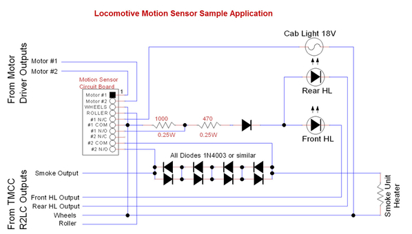
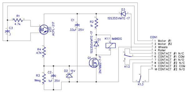
If you're up to building a board from a parts kit, I offered these a while back.  This is a module that simply detects when the motor(s) are running and closes a relay.  With that you can do a number of things, the sample application illustrates automatic cab lighting, Rule-17 headlight feature, and two-level smoke, reduced when stopped.

mceclip0

Sample Application wiring.

Locomotive Motion Sensor Sample Application

Circuit Schematic.

Locomotive Motion Sensor Rev. 4 Schematic

Attachments

Images (3)
  • mceclip0
  • Locomotive Motion Sensor Sample Application
  • Locomotive Motion Sensor Rev. 4 Schematic

Ed, I’m just a couple weeks behind you on the same project.   Working on a 3 Unit power (2 powered TMCC and 1 dummy).  I haven’t pulled the trigger on the ERR Cruise Commander and Railsounds boards just yet.  Another option I’m considering is picking up another UP TMCC Sd40T-2 and swapping cabs.   Now that you have done the ERR and know what the limitations are, any suggestions? 

Last edited by Steims
Steims posted:

Ed, I’m just a couple weeks behind you on the same project.   Working on a 3 Unit power (2 powered TMCC and 1 sunny).  I haven’t pulled the trigger on the ERR Cruise Commander and Railsounds boards just yet.  Another option I’m considering is picking up another UP TMCC Sd40T-2 and swapping cabs.   Now that you have done the ERR and know what the limitations are, any suggestions? 

The problem with two of the exact same SD40t-2's (same internal but different shells) is that you will get shutdown sound from both engines since both have the exact same railsounds board. Even with them programmed to different engine id's. I have the UP 6-28540 (4004) and now the UP 6-28255 (4551). The 4004 is TMCC and now the 4551 has been converted to TMCC. Once I got past the figuring out how the lights worked the rest was easy. Both engines work great together.

Ed

Add Reply

Post

OGR Publishing, Inc., 1310 Eastside Centre Ct, Suite 6, Mountain Home, AR 72653
800-980-OGRR (6477)
www.ogaugerr.com

×
×
×
×
Link copied to your clipboard.
×
×