
I'm building a control panel and I want to use LED's to indicate turnout position. I'm using Tortoise Switch Machines controlled with DPDT toggles mounted on the panel, powered by a 12V wall wart.  Couple questions:


1. Can I get Bi-Color LEDs Green/Yellow or are they only Red/Green?


2. Do I need to use resistors or can I wire direct to the LEDs?


3. Source part # for the Bi-Color LED's?


4. Simple wiring diagram how to wire the toggles to the LEDs? (Something I don't need to be an electrical engineer to understand)


5.  If I can't get Yellow/Green Bi-Color LEDs, and I use seperate Yellow and Green LEDs, hows does that change the wiring?


Original Post

Replies sorted oldest to newest

Good morning,

  I have bought my green/red LED's from this source:  http://www.mpja.com.  It was part number 17136 OP.  They also have 3mm yellow green number 18037 OP.  These are 3 mm - 3 lead common cathode.  If you want 5mm they only have the 2 lead ones which is part number 17142 OP.  I will be using SPDT Mom - Off - Mom switches (5009 SW) with diodes (1n4001) on the outer leads with a 100 ohm 1/4 watt resister on the cathode.  I am of course running these off of AC for the Lionel 022 switches.  My Ross switches will use NO push button switches also purchased from MPJA (5019 SW) with the yellow and green wires connected directly to the outside leads without diodes but a single resistor again on the common cathode.  If you do a search on my user name, you will come up with the topic where I asked how to do this.  I included a drawing for simple hookup which the major electrical gurus all said looked correct and would work.  Hope this helps.


Jared

Interesting to note that DZ 1002 switch(turnout) control buttons have the LED's installed. The red and green led's plug-in and can be reversed in either the switch motor or the push buttons.  Atlas has a switch motor controller that also has LED indication. Please note that both these parts are components of a remote switching system.  You should review the complete system, either DZ or Atlas, and the wiring diagrams.  I've use both systems extensively. The Atlas system with the 6924 relay boards.  I have never mixed component parts.


Last edited by Mike CT

What are the Pros/Cons in using a 3 lead LED versus a 2 lead LED?


I found this link with a very simple wiring diagram which I understand.

http://www.sierrascalemodels.com/Art_Lighted.htm


If I use a 12V LED, do I still need to use a resistor?


I'm ready to drill for the toggles and LED's but haven't decided whether to use 3mm or 5 mm LED's.


IMG_0551

Attachments

Images (1)
  • IMG_0551
Last edited by Former Member

"What are the Pros/Cons in using a 3 lead LED versus a 2 lead LED?"


Two-lead LED:

One color per LED; e.g., Green, Red, Yellow, etc.

If you want to have a Green and a Red indication, it would require two LED's; one for each color.


Three-lead LED:

Two colors per LED; e.g., Green & Red.

If you want to have a Green and a Red indication, it would require just one LED. This means half as many holes in the control panel.


Whether using two, single-color LED's, or one bi-color LED, the wiring would be the same; i.e., one common wire, and one wire each for Green and for Red.


Hope this helps,


Alex

Bipolar LED's are one color for one polarity, and another color for the reverse polarity
Note the marker lights on the front of this Weaver E-8 model. Same LED, reverse the polarity and the color changes.  These LED's are not 12 volt.   The attached wiring diagram was provided by TAS (Train America Studio) for the upgrade to add the lights to their EOB system at the time.

Last edited by Mike CT

OK Thanks Alex, thanks makes sense. The 3 lead LED is center comon, then 1 leg for each color. I would really rather have a yellow/green LED but just cant find them so I guess I'll go with the Red/Green Bi-color.


David I been looking on Ebay and it looks like thats where I'll get them from and the plastic holders. Seem mounting them and swapping them out is much easier with the holders.


I guess my final question is do I HAVE TO have a resistor wired in there or can I just hook the LEDs directly to the switch toggle? I see many of the LED's on Ebay say 12V, and I am using a 12V wall wart for power. I thought I read somewhere in one of Matts post that their club layout is using LED's with their Tortise machines direct with NO resistors.

OK I found this instruction note on the Tortoise site. It shows exactly how to wire my Tortoise and 2 seperate LEds to my panel. Very straight forward and I can understand it. I think this is what Matt was referring to in another thread about this same thing.


The question is: How do I change the wiring for a single Bi-Color LED? and is this for a SPST or can I still use my DPDT toggles?


Attachments

Files (1)
Last edited by Former Member

Hey Alex, I checked out that site earlier after you posted it, and I saw that orange/green LED. I did find a yellow/green LED on a site that Jared posted above, but they were only 3mm instead of 5mm. I know...now I'm really being picky! I'm going to have to run to Radio Shack in the morning just to pick up a cpl different samples and sizes to play with I guess. I'm sure I'll pop a cpl of them while experimenting.


I really like that wiring diagram that I posted from the Totoise site, but I gotta figure out how to wire it with 1 bi-color LED instead of the 2 different ones as they show. Also figure out whether that diagram is for a SPST or DPDT toggle.  

Thanks Jared.


After a quick trip to radio Shack to get a few different LEDs and resistors I came back home and played around a bit. I don't know why I was making it so much harder than it really is. I used the Tortoise wiring diagram and substituted 1 Bi-Color LED with 2 leads, instead of 2 different LEDS as they were showing. Works like a champ and didn't need any resistors running it through the Tortoise itself.


Now I need to look for a Bi-Color LED Green/Yellow with only 2 leads instead of 3 leads. Then go drill a bunch of holes!


wiring-leds_7

Attachments

Images (1)
  • wiring-leds_7
Last edited by Former Member
Originally Posted by Carl Tuveson:

Here is what I used on My control panel.


Carl

Umm, there might be a slight problem and maybe Gunrunner can verify.  The tortise motor resistance acts as a ballest resistor to current limit one LED/diode set which lights accordingly.  However, If using a second or third indicator sets, you would need  to place a 100 ohm resistor just before or after every LED/diode combinations. Otherwise I believe one LED/diode set will light and the other set(s) dim or not at all.  Reason is LEDs/diode forward drops may not draw equal current, so one or other LED/diode set gets all the current (current hogging) and lights brightly, while "starving" the other set(s).  So you might get one set to light red but not other but then second set lights green but now first set green fails to light which to leads to great hair loss (see my avatar picture for verification)!  :0

Well I found the Bi-Polar Yellow/Green 5mm LEd's for 20 cents here: I ordered 50 of them for our panel.


http://www.elexp.com/opt_3362.htm


I wanted the Yellow/Green because thats what I see in our yards at BNSF and the UP. Every switch has a 1 light, Yellow/Green, thats right at the switch motor. Obviously Green indicates normal position (that does not always mean straight) and the Yellow indicates the "Alternate" route. Our layout has several switches that normal position is NOT straight, so even though the switch is thrown for the curve, it will show green as lined for "normal" position.


The Bi-Polar LED allows me to wire them as the Toroise instructions show. Very easy, even for me, and less wiring because I'm only using 1 LED.  

Laidoffsick,


Looks like you got your answer.  I basically used color LEDs each with a diode and resistor.  I will be using them for a few 022 switches, a few DZ1000s and as an indicator for track sections that are out of sight. 


BTW your control panel looks great. However, can you tell me what you used to build your panel and the track schematic.


Thanks

Thanks Anthony. It's a piece of plexiglass that was 20" x 32". I used RR Tracks software to design the layout, so I just resized the track plan using PhotoShop and took the file to my local Office Depot to print it out full size.


This is the full size printout I had done at Office Depot. Just take them a PSD, BMP or JPG file and they can resize it for you if you don't know how.

IMG_0529


 Here I cut the track plan out to fit my 20" x 32" piece of plexiglass. I left the protective film on the back and taped the track plan to the back of the plexiglass.

IMG_0532


 Stopped by the Auto Parts Store and got some 1/8" and 1/4" wide pin striping in various colors.

IMG_0534


 Then just pick your colors and lay the pin striping down. Take your time and the tape will curve nicely following along the track lines of your printout.

IMG_0538


 After your lines have been traced with the pin stripping, remove the track plan printout from the back, and tape off the front side to protect your stripes and the clear plexiglass so you cant paint the back of the panel.

IMG_0543


 I spray painted the back of the plexiglass with white spray paint after removing the protective film. Several light coats, and then spayed with silver just to protective the finish from scratches. It doesn't have to be silver, thats just what I had.

IMG_0551


IMG_0552


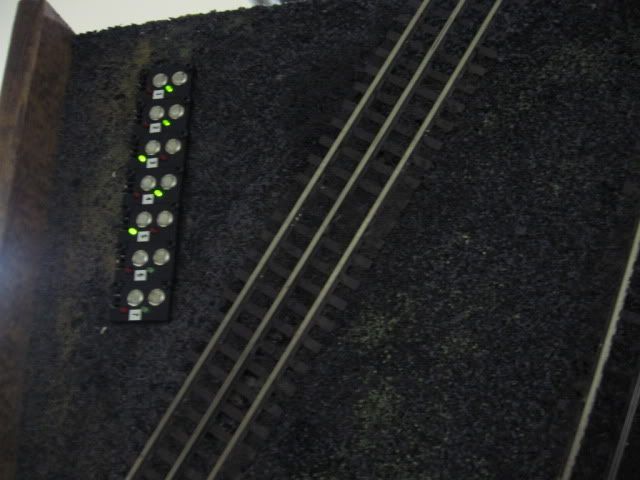
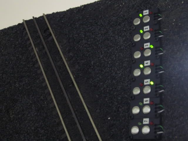
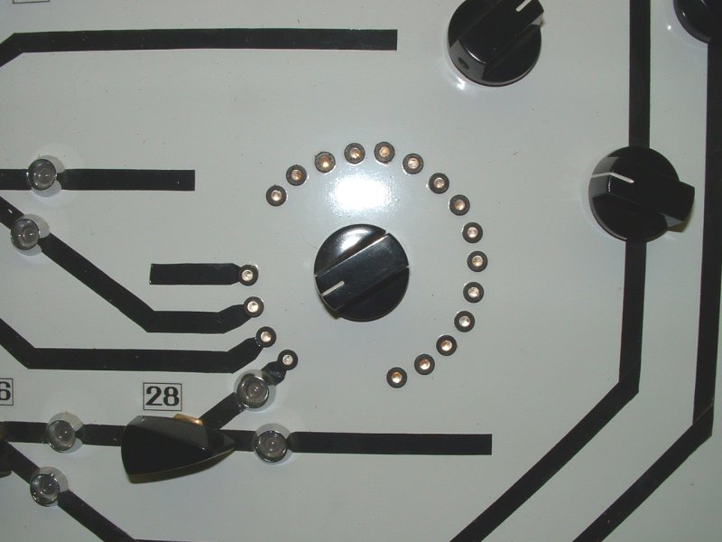
 Switch toggles installed. We havent completed the track work so only the tracks that have been installed were laid out on the panel. We will add the other tracks later. Also need to add the toggles for the track blocks, build a frame to hold this panel, and build the box to attach it to. More to come later.

IMG_0556


When drilling these 1/4" holes for the toggles, I used 4 different size drill bits to prevent cracking the plexiglass. Drill a small pilot hole, move up a couple sizes in drill bits and drill again. Take your time and don't use a lot of pressure or dull bits because you will crack it. 

Attachments

Images (8)
  • IMG_0529
  • IMG_0532
  • IMG_0534
  • IMG_0538
  • IMG_0543
  • IMG_0551
  • IMG_0552
  • IMG_0556
Last edited by Former Member

Laidoffsick


Really appreciate your reply and especially the details on construction of the panel.  Please keep me posted on your progress.


As an FYI, I am currently building a 3 layer layout (10x 40) with a yard area and subway.  I've decided to build 4control panels, one for each layer and the yard with the turntable.  I really liked the smooth curves you created using auto tape over plexiglass.  I've tried this about 10 years ago on my last layout (8x28) and used the tape over a steel sheet but just could not get the smooth curves.


I will now use plexiglass and with RR track attach the track schematic to the back of the glass as you have done. 


How do you intend to protect the tape once your panel and tracks are complete?


Here is a photo of my old panel which include toggle switches for block and LEDs for turnouts and track occupancy.


 Again thanks for your help

 Tony


S3500033

Attachments

Images (1)
  • S3500033

Thanks Anthony, that's a good looking panel you had there.


There's not really any reason to protect that pin stripes once they've been pressed down. It's very durable, and stuck to a clean smooth surface, just as it would be on an automobile. It's intended to be used on automobiles with no further protection, so unless you pick at it to pull it up, it's not going anywhere.


The only suggestion I would make is when painting the back, putting many coats on for protection. The thicker the paint on the back, the better. A deep scratch will show through to the front because the plexiglass is clear. It's exactly the same as painting an RC body. just without all the curves and contours to deal with. If you wanted to be very creative, you could paint all the track lines on the back, instead of using the pin stripes on the front. I've done many RC bodies in the past......that is a lot of work and forces you to do it in reverse order, and light color to dark colors. I think the pin stripes with hold up just fine over time! :-)

Thought about doing that, and it would be easy to do using the RR Tracks software. Just flip the entire track plan (basically it's a mirror image) and then tape it face down to the front of the panel, pin stripe the back, and paint over them with the white paint. That would leave the face of the panel completely smooth, except for the toggles sticking through.


The only downside to that, and the reason I didn't do it, is because once you paint the back, there is no adding to it. Our tracks are not completed on the layout, so I will have to add all the industry tracks and engine service tracks once we get them in. This way, adding to the current planel is easy, just put down more pin stripes.


We are at the point in the layout building where much of the wiring had to be done, requiring the panel be installed. Track blocks and turnout control in order to stop doing all the wiring temporary and re wiring later. We can run trains on all 3 mainlines now, conventional or command, but need to wire the track blocks for sidings and the turnouts to utilize the reverse loops and grade tracks between levels.


If the entire track system was complete, I probably would have put it all on the back of the panel.  

Well another lesson learned the hard way.... Do NOT use Plexiglass (acrylic) for control panels. It's too brittle and very easy to crack. After spending hours and hours on our panel, framing it, painting the frame, sanding, and painting a few more times, I broke it while drilling holes in it for the LED's. Even drilling pilot holes, using several bits working up to the final size hole, the bits catch and crack the acrylic. A couple of them were very small and I could live with, but the final one was about 6" long right through the roundhouse area. Its toast!
 
Went and bought a sheet of Lexan after reading some stuff on the net. It cost twice as much, but is several times more durable and stronger than acrylic. I put a small sheet through a grueling test of holes and bends. Dull bits, holes right next to each other, pilot holes, no pilot holes, the whole nine yards. So I'm off to get a big sheet of Lexan tomorrow from Lowes and build the panel AGAIN!   
 
Originally Posted by Anthony:

I will now use plexiglass and with RR track attach the track schematic to the back of the glass as you have done. 

Originally Posted by Rich883:
Wow, sorry to hear of the issue. I ran into the same thing on the power distribution panels I built, plexiglas cracked, changed to lexan no issues.

And now I learned something. That Lexan and Plexiglass ARE two different masterials.  Always thought they were different names for same material.

Originally Posted by rrman:

And now I learned something. That Lexan and Plexiglass ARE two different masterials.  Always thought they were different names for same material.

Actually Lexan and Plexiglass are just the "brand names" of Polycarbonate and Acrylic. Acrlyic (Plexiglass) will shatter into larger pieces, thats basically what happened to my control panel. Polycarbonate (Lexan) is shatterproof and much more durable, that's whay they use it in banks at the teller windows, referred to as bullet proof glass.


Even at Lowe's, they have a poster on the wall explaining the difference between them. Acrylic (Plexiglass) is 50x stronger than glass. Polycarbonate (Lexan) is 250x stronger than glass.


Guess I shoulda done more homework on that before I wasted about 30 hours using acrylic for a control panel.

I have been machining acrylic for most of my career. If done properly, it will give better results than polycarbonate which is softer and scratches quite quickly due to that characteristic. Stepping up drill bits and using sharp regular bits is why you are cracking it. Use the correct size for the finished hole size. Buy a negative rake plastic bit, higher speed and slower feed rate. Dish soap and water makes a good lubricant. Or use a high speed dremel or drywall cutter with a spiral up router bit so you can control feedrate when drilling without drill press. Usually it is the multiple stepping with a very sharp standard drill bit that cracks the acrylic because is acts like a wedge and sucks into the material faster than it removes it. With proper blade it also cuts cleaner than polycarbonate on a table saw or when template routing. I CNC route both and also aluminum. And you can edge polish and solvent bond with nice strong joints. Which is not possible with polycarbonate. Polycarbonate does make nice bullet proof windows if about 1" thick. FMH

Laidoffsick


Read your comments and sorry to hear about the end result after some 30 hrs of work.  Really appreciate your efforts on updating this thread.  I did purchase a single sheet just for doing a mockup.  BTW the tape worked fine following your suggestion to use patience when making curves. 

I am in the same position as you are as I need to build a control panel to complete the wiring for this phase prior to proceeding to the next phase (almost in critical path).  My layout is 10 x 40 with 3 levels including a yard area with a TT  and roundhouse.  So I need to build 4 control panels; a panel for each of the 3 levels plus a 4th panel for the yard area. 


Going forward I will purchase the polycarbonate material and will make another mockup and test drill several different size holes. 


BTW last year I stopped at a local sign shop and the owner recommended using a material made of aluminum that has a special white facing.  He can transfer the track schematic from a PDF file (converted from RRtrack) directly to the aluminum sheet.  I going to revisit this option and compare costs.  I believe it was about $50 per control panel.

Will keep you posted on my progress.


Again thanks and keep on building.

The process is called Direct Output to Substrate. It is a digital printing process that can also be done to your acrylic, styrene, Epvc, or PVC. And I would recommend that you have your sign guy cut the holes, print it subsurface on 1/8" or 3/16" non glare acrylic sheet and then back spray with a polyurethane acrylic enamel or plastic plus screen ink. It will look very professional, resist scratching, and look good for a real long time. Your lifetime anyway. Using polycarbonate is the wrong product for this application. It will sag (cold flow) and your fine line tape will eventually peel due to the plasticizers in it. And unless you abrade it with Scotchbrite ( forget sanding polycarbonate ) the paint will also not adhere well either.
Post

OGR Publishing, Inc., 1310 Eastside Centre Ct, Suite 6, Mountain Home, AR 72653
800-980-OGRR (6477)
www.ogaugerr.com

×
×
×
×
Link copied to your clipboard.
×
×