There are many old threads on re-wiring a Williams loco in series to slow it down. Mainly after adding a ERR sound board so it will operate with complete sounds, motive, horn, and bell, at 0r below 10 volts AC. Can anyone answer exactly that after wiring the motors in series, that less voltage is required, and the engine will run slower so the sounds can be activated accurately. All input is welcomed and appreciated. Thanks in advance for your responses'...![]()
Replies sorted oldest to newest
I rewired about 10 of mine in series with True Blast Plus and the sound works just the same as when wired in parallel. No problems here.
It should run half as fast for the same track voltage as it did with the motors in parallel. Am I missing something about the question? For the same track voltage, speed should be half and current draw should be half. These figures probably fall apart at extremely low track voltages, around 3 volts or less.
It will also be less susceptible to low voltage spots in the track by a factor of four over the stock, parallel wired locos.
When wiring in series MORE voltage is required, because each motor only gets HALF of the track voltage.
With every discussion of wiring the motors in series, someone always chimes in with "if one truck slips, the other will stop." While that is true in theory, I have never seen it happen with dozens of series-wired locos and over at least fifteen years of service. So don't worry when someone says that.
I've wired all of my K-line engines in series. Never had a problem.
You can wire the motors in series, and you can also just use a string of series diode pairs to reduce the voltage to the motors. While wiring in series works, there are some downsides. One issue is that if one motor loses traction, the other truck will stall as the free spinning motor will draw much less current. With parallel wiring, that doesn't happen.
Series diode pairs serves to drop the motor voltage while still having additional voltage to the sound board.
gunrunnerjohn posted:You can wire the motors in series, and you can also just use a string of series diode pairs to reduce the voltage to the motors. While wiring in series works, there are some downsides. One issue is that if one motor loses traction, the other truck will stall as the free spinning motor will draw much less current. With parallel wiring, that doesn't happen.
Series diode pairs serves to drop the motor voltage while still having additional voltage to the sound board.
John- do you have a sketch of how to wire the diodes, and diode size? I would try it on any future engines that I buy.
Bob
Rewiring the motors in series is the 1st thing I do to all my Williams. They run so much better this way I don't know they aren't like this from the factory. Nobody needs a top speed of 1,500 mph!
Here you go, you can use either diodes or bridge rectifiers. Frequently, it's more convenient to use bridge rectifiers, less wiring. Obviously, you can vary the number of diodes pairs or bridge rectifiers to achieve the proper balance between track voltage and speed of operation.
Attachments
Diodes vs. series wiring
One of the benefits of series wiring is that you not only lower the top speed, you double the usable range of the throttle. Advancing the throttle enough to add 4 volts to the track only adds 2 volts to each motor in a series setup. Once the motors start running in a diode setup, advancing the throttle 4 volts still adds 4 volts to each motor so the speed increases at the same rate as without the diodes. Only the top speed is decreased due to the diodes. In my opinion, series wiring is superior to diodes.
As to the supposed problem with one motor losing traction, this is really only a problem with very early Williams diesels that came without traction tires. Virtually every other 3-rail diesel has traction tires on both trucks so losing traction with either truck is not an issue.
What a great thread, and very pertinent to what I’m trying to accomplish. My Williams sharknose ABA is a speed true demon with little low end pulling power (especially considering how heavy it is) and with a relatively small range of speed adjustments. Trying to run slowly, it stalls around curves at slower speeds, and then suddenly rockets down the straights at .89 mach. My K-Line SW-1 does this too. Does wiring in series eradicate these traits? Is the wiring job as simple as connecting each motor’s + lead together, and doing the same with their negative leads?
I haven’t had the shell off of the Williams or K-Line in quite some time, anyone have photos of their wiring job?
Tom
I had a problem with a Williams GG1 where the Tru-blast horn would not work at slow speeds, presumably due to low track voltage. Series wiring solved this.
Bob
I have Williams E7 AAs with both A Units wired in series as well as F7 AAs Both units in Series and they pull a string of 15 Railking 60 Foot passenger cars without a problem on my layout at about 13 volts from my Z4K.
FlyPlanes-PlayTrains posted:Does wiring in series eradicate these traits? Is the wiring job as simple as connecting each motor’s + lead together, and doing the same with their negative leads?
I had this explained to me awhile back, but I haven't gotten around to doing it yet. I believe you simply pull the + lead off of one motor, then tape it off (insulate the loose wire). Pull the - lead off the other motor and tape it off. Then make a new jumper wire to connect the two motors together.
I believe that's what your supposed to do, someone please correct me if this is wrong.
<>Is the wiring job as simple as connecting each motor’s + lead together, and doing the same with their negative leads? <>
Nope. That is wiring the motors in PARALLEL, which is how they are already wired from the factory. Series wiring means that the power goes through one motor, then through the other motor before going back to the PC board.
Here's how to do it.
Wiring motors in series:
The motors have two wires attached to them. They could be any two colors, but for purposes of this discussion, we will assume that each motor has one blue wire and one yellow wire, OK?
-take off the shell
-Follow the blue wire from one motor back to the board and snip that wire at the board.
-follow the yellow wire from the other motor back to the board and snip it off at the board.
-now you have one motor with a long unattached blue wire, one motor with a long unattached yellow wire and two wire stubs on the board.
-take the long unattached blue wire from one motor and connect it to the long yellow wire from the other motor. You can connect them with wire nuts, or solder and heat shrink.
-put some tape or heat shrink on the stubs of wire on the boards if they can touch anything.
-test drive the loco before putting the shell back on.
That's all there is to it. Your loco will run more slowly and be less inclined to slow down in spots where the track voltage is low.
There are other ways to handle the wires at the board, some that are more easily reversible, but this is the quickest/easiest way.
Mixed Freight's explanation is electrically the same as mine, just a different way to do it.
gunrunnerjohn posted:You can wire the motors in series, and you can also just use a string of series diode pairs to reduce the voltage to the motors. While wiring in series works, there are some downsides. One issue is that if one motor loses traction, the other truck will stall as the free spinning motor will draw much less current. With parallel wiring, that doesn't happen.
Series diode pairs serves to drop the motor voltage while still having additional voltage to the sound board.
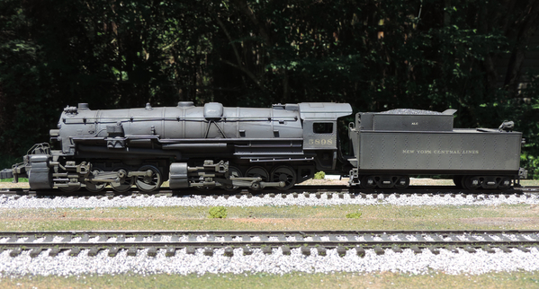
Absolutely - but, I have a NYC 0-8-8-0, "customized" from a RK 2-8-8-2, with TAS TMCC (no cruise) and the twin motors wired in series, and I have seen this occur only once since I built it several years ago. The issue is real, but its frequency, at least on my gnarly old layout, is rare.
If it occurs a lot, the diodes are the way to go.
If it had cruise control I might not have even bothered with the series wiring.
(3RO loco; 2RO photo tool.)
Attachments
This is the diagram to convert parallel to series. Hope this helps.
I always wire it with motor 1 being the front motor.
Attachments
I've done all my K-line's by clipping the two yellow wires and soldering them together. This accomplishes the same thing and is easier than digging into the boards.
This is a S2 I did a while back. Remember, K-line motors spin in opposite directions. Not sure about William's.
Attachments
Of course, for most steamers with one motor, the diodes are the only game in town. ![]()
Thanks for the great responses from everyone', The main point I want to accomplish is to get the ERR sound board to operate at full capacity which requires 10 Volts AC, and not have the williams loco run at high speed which it will do at 10 VAC.
Shout out to Royboy: Some how I inadvertently deleted the informative E-Mail you sent'.. I am so thankful that you chimed in on this thread. I have printed your instructions. Thanks again.
Gene H, and GRJ, thank you both for your input. From looking at my K Line and Williams models, It appears K Line is wired similar to Lionel. WIlliams is different again from just comparatively looking.
Well, I finally got around to hooking up my first loco's motors in series (WbB U-33C), and boy is it ever nice now! It runs like a scale model train instead of a hyper-sonic slot car!
After studying the stock wiring, doing the series motor connection proved super easy. For the front motor, I removed the blue wire/female crimp terminal from the plastic plug that connects to the reverse board. Next I removed the rear motor's yellow wire/female crimp terminal from its plastic plug on the reverse board. Then I shaped a simple tiny U-clip from a piece of 16 ga. solid copper wire. I plugged the female crimp terminals onto this tiny copper U-clip, thereby connecting the blue and yellow wires together. Lastly, I slipped on a piece of heat shrink tubing, and applied some soldering iron heat to shrink it on. Wah-La........ instant non-permanent electrical connection! No cutting/stripping/splicing/soldering/wire nutting/taping of wires. And I can EASILY resort back to the factory set-up if I ever want to. Not sure why I would want to, but that's beside the point.
Many thanks to everyone on this thread and a previous thread a few months ago for all the great explanations and diagrams. I believe I got about 6 more WbB locos to convert, and hopefully they'll all go as quick and painless as the U-33C! ![]()


