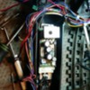
I am replacing a blown Western and Pacific GS-2 Premier 2.0 board with an upgrade 2.0 board. (A wire was pinched and shorted on the boiler) There are 3 wires hard wired into the old board and plugged into a component mounted on the boiler. A red, yellow and black, please see the pictures. I don’t see anywhere these attach to the new upgrade board. What should I do? Also the manual shows mounting the new board into the tender, but my original board was mounted in the engine and I was just going to keep it there. Will I be ok?
Replies sorted oldest to newest
Just remove them, no longer needed. The upgrade PS-2 3V board has that regulator on the board. G
As long as you can fit the board in the locomotive and craft a decent heatsink to bond to the frame, you can leave it in the engine. Mounting the board in the tender will require you basically doing the whole upgrade, all the connections will change.
thank you G and John for the quick help. crafting a heat sink will be tricky. It is a dumb question but just in case, will it matter if the board is mounted upside down. I am guessing it will not. thanks again for the instruction.
Blake
It does not matter how you mount it. Upside down is OK.
For the premier Northerns I have mounted the board in the shell with the upgrade kit heat sink. Look at the available screw holes, but you typically can get the board mounted on those holes at the front. I clip off the back exposed plastic mount (closest to the relay). I rotate the heat sink so it is towards the rear, not the side. When you do this you will notice a bottom edge of the heat sink can touch the 4 rectifier legs. I have a set of cutter pliers that I can fit over it and I trim off a 1/4" of heat sink that is under the rectifier.
You will then see that the heat sink hole lines up close to another hole in the shell. At this point the board is in the shell and you can plug wires back into the board. Just make sure you transfer the black connectors from the old 5V board to the new 3V carefully. Some of these Northerns are large enough, you can place the battery in the frame near the forward drivers. Or leave in tender, just modify for the 3V. I have done quite a few FEF (they seem to have a high 5V failure rate), a GS-4 or 2, and some ATSF Northerns. All pretty much the same way. G
George, have you noticed many of the OGR Members who know how to fabricate are old Hot Rod guys from back in the day? Make it fit and work somehow-someway.
Good point! G
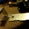
Thank for instruction about the board orientation. Between the old heat sink and the one that came with the upgrade kit and a weld I was able to fashion one to fit into the boiler. I included pictures just it case it might be helpful to someone trying to done something similar. The next problem is a connector issue. I have included a picture that shows the connectors are slightly different. The raised slots are slightly closer together so the old ones don't fit. Any suggestion here?
Blake
Attachments
You have to take the old connector shells off the 5V board and put them on the 3V board. The pins are the same, but the connector shells are different.
A little heat on the shells softens them up and makes it easier to work them off. It's obvious, but be careful removing the ones from the new board as you don't want to damage traces under the connector.
George, have you noticed many of the OGR Members who know how to fabricate are old Hot Rod guys from back in the day? Make it fit and work somehow-someway.
Or motorcycle guys![]()
Thank for instruction about the board orientation. Between the old heat sink and the one that came with the upgrade kit and a weld I was able to fashion one to fit into the boiler. I included pictures just it case it might be helpful to someone trying to done something similar. The next problem is a connector issue. I have included a picture that shows the connectors are slightly different. The raised slots are slightly closer together so the old ones don't fit. Any suggestion here?
Blake
Blake, you missed my second paragraph above. I mentioned swapping connectors.
Neat fabrication!
George, have you noticed many of the OGR Members who know how to fabricate are old Hot Rod guys from back in the day? Make it fit and work somehow-someway.
Or motorcycle guys![]()
Good point, I actually started with MC. Raced MX. Lots of fabrication back in those days! G
Sorry G I did miss that last paragraph, thanks. Thanks, John for tip. I will going on this asap.
Blake
Focus on my last word which is "carefully". Easy to bend pins, but if you use a thin flat blade you can work them off easily. Just work each end slowly.
No need for you to break out the welder to repair the pins. ![]() G
G
G thanks for the advice. Completed and reinstalled. Preliminary test per upgrade manual was good. powering up to 12 volts and taking 1.7 Amp a lot better than the 8 Amps on the old 5 volt board. Everything as is the manual suggests, except the number lights adjacent to the headlight blink and when the engine enters into reverse the back up light comes on, but when returning to neutral from reverse the back up light blinks. I am hoping this all corrects itself when I down load the GS-2 files.
Blake
1.7 amps seems a lot of current for an idling PS/2 locomotive, I don't get nearly that from any of mine. That seems excessive current draw. How are you measuring it?
Measuring Amps with a Z4000 display. I think the reason it might have been high was due to an uncharged battery. I have since tried it again and it is now reading 1.0-1.1.
That is until I put the engine in forward then it jumps as high as 7amps. I am pretty sure there is a short in the motor and I am going to try to order a new next week.
Thanks for all the help,
Blake
make sure the purple wires or the whit and yel motor wires are not nicked or have wire strands/solder touching chassis or motor cans.
You have some sort of wiring issue, you need to resolve. Disconnect motor leads from PS-2 board and power with battery and see how it responds. Meter in line for amps will tell you if the motor is bad. G
Like George says, you still have a problem. Idle current should be around .2 amps, not one amp!
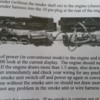
Again, I really appreciate the help. I disconnected the yellow and white harness from the board and still get the 1.0 amp when powering up to 12v. I reviewed the manual again and included a portion in the picture below. It does say up to 1.0 amps. Maybe MTH changed something?? But, with the yellow and white leads disconnected off the board and motor it should rule out any short of these two wires. How many omhs should the motor read to be considered not shorting out?
Blake
Attachments
If you have smoke on and power up you can be at 1A. Board, smoke and bulbs.
If smoke off and only load is bulb (1 or 2), as John says the load would be about .2 to .3Amps. Higher means a heavy battery load or a short some where. IF sounds and all functions are ok and you turn power off and it plays shutdowns sounds properly, you may be ok. But the MTH instruction is not right from what I see and even a fully loaded diesel with lights and smoke is about 2A for slow speed movement.
Shooting up to high amps means either AC short, or that PV short. Motors, heat element, lights and couplers.
Can the diodes under the engine PCB be touching the frame? PCB wiring shorted to chassis? G
OK. I put it on a new test track and powered to 12v and got .7amps with everything connected. I unplugged one thing at a time turning the power off in between. I unplugged the engine harness from the boiler connector @ 12v - 0 amp so I plugged that back in. Unplugged the tender harness 12v - .5amp. Unplugged the motor connector off the board no change. Unplugged the 6 pin @ 12v 0 amps so I plugged that back in. . Unplugged the 12 pin and it dropped from .5 to .2 amps. Unplugged the 8 pin and it dropped from .5 to .3 amps. I never uploaded the sound files so the sounds are the test sounds for the bell and whistle, they were working but not any more.
From the above info summarized: tender .2 amps 12 pin .3 amps and 8 pin .2 amp which one do think is out of line. and does anyone know what the normal resistance should be across the motor poles?
Blake
Depends on the motor but they run from 4 to 12 ohms.
Is the conventional volume adjusted up, no test tones is an issue. It is easy to blow the audio amp if you had a wiring mishap. Speaker measure 4 ohms with no short to chassis? G
The motor reads 0 and the speaker close to it. I am waving the white flag. Should have checked the resistance on the motor BEFORE I connected it to the new board. G would you like a crack at it? If so my e-mail is wings2x4@sbcglobal.net. let me know.
Blake
E-mail sent. G


