
Daniel Auger posted:
Adrian! posted:

...Now with the TIU and WIU connection (with the USB port on the TIU) the logic on the TIU board is powered by the +5V coming on Pin 1 instead of track power...

If you have an elegant proposition to get rid of this power coming from the WIU (via USB), that would solve this problem and at least one more that I know: The more complicated reset of the TIU after the use of the Emergency Button when a WIU is present.

Would the USB work properly without Pin1 ?

Thanks for your post !

+5VDC from the WIU is not required for anything if you have some other power source.

You can snip it. Snip it good.


Adrian-  very interesting thought. I’m not 100% certain on this (now I need to go do some experiments of my own) but from earlier debug that I was doing on a faulty WIU when they first cam out  I am under the impression that the +5v from the USB port is only supplying VDD to the  USB -> RS232 converter inside the TIU. 


enginEErjon posted:

Adrian-  very interesting thought. I’m not 100% certain on this (now I need to go do some experiments of my own) but from earlier debug that I was doing on a faulty WIU when they first cam out  I am under the impression that the +5v from the USB port is only supplying VDD to the  USB -> RS232 converter inside the TIU. 


I'm literally verifying that as we type.

I think you're right, that would make more sense. Using the external VDD for the FTDI chip is recommended by the FTDI guys to ensure that the logic threshold is well defined. Still the main power LED comes on so I think there may be power to at least the FPGA and some of the other logic (not the drivers like you're suggesting)

The aux power definitely turns on the the drivers though.

~Adrian

Last edited by Adrian!

I'm thinking of a laying out a little daughter PCB and adapter that fits the SOIC-20 footprint for the ACT244 in the TIU that roughly looks like this:

flip_circuit

It's not elegant but should be pretty indestructible from the output port. Id use a quad op-amp chip like a LM339  and do everything with SMD. I think I could get it down to 20x20mm with maximum layout effort applied. Looking at the drawing I'll need another current tap on the VDD rail since the 244 can either source or sink to self-destruction.

   Since the load will be inductive it's sort of LPF filtering the current, so it can't rise too quickly. Assumptive calculation puts the self-inductive time constant on the order of 10 us, so any old opamp should be fast enough...

Attachments

Images (1)
  • flip_circuit
Last edited by Adrian!

Here's a more elegant scheme after some thinking...

flip_circuit_improved

The ACT244 is 50mA per output with 4 ganged together on the TIU board so you probably want to limit it to 200mA. Since VDD/GND is well defined you can put your series current sensing resistor there. So if the top comes down by 200mV or the bottom comes up by 200 mV (200mA through 1 ohm) it's time to turn stuff off with the comparator. Just a plain old resistor ladder to define the thresholds. Band limiting capacitance is of course implied at comparator inputs. The resistors are 1 ohm and will have up to 200mA flowing through them so I^2R says 40mW dissipated and 1/4W parts are fine.


The resistor voltage drop at the source terminals means you're going to eat into the VGS of the MOSFETS by 200mV at most.. so you need a threshold voltage lower than 5V-0.2V = 4.8V which seems reasonable for a typical HEXFET. Any old complementary pair like IRF9620 / IRF620 (Vth 4V worst case) should work reasonably.

The comparator would be preferable to be single supply. It needs to be a bit beefy to drive the HEXFET gate capacitance (350 freaken pF for the PMOS) with reasonable speed. If we say we want the 5V transition in maybe 10us that means 

Ireq = C deltaV/deltaT  .... Ireq = (350pF)*(~5V)/(10us) ... so about 0.2mA of current minimum. I guess an LM397 would fit nice... at least 6mA output drive, single supply, wide range.

Finally the diodes. The output is going to be clamped between -Vdrop and Vdrop+5V so we don't want the forward voltage to be too high. Back to the ACT244 datasheet it says the VCC can be as high as 7.0V so we can assume the output driver breakdown voltage is at least that. That sets Vdrop less than 2V. We also want something fast acting-ish and able to take a hit. Maybe a 1N493x series.... voltage drops in the 1.2 V range, at least 50V reverse bias suitability, and recovery time in nanosecond land.

The whole set of parts to protect 4 channels in my digikey cart is about $30 including a proto-board to solder them on... which doesn't seem so unreasonable.


Maybe a good weekend project?

Attachments

Images (1)
  • flip_circuit_improved
Last edited by Adrian!
enginEErjon posted:

Adrian-  very interesting thought. I’m not 100% certain on this (now I need to go do some experiments of my own) but from earlier debug that I was doing on a faulty WIU when they first cam out  I am under the impression that the +5v from the USB port is only supplying VDD to the  USB -> RS232 converter inside the TIU. 


Thought about the scenario more after measuring. It's correct that the WIU won't cause this problem (logic on and pumping a shorted track).

I'm thinking it still exists in some ways though... if you have different power going into FIXED 1 than FIXED2,VAR1,VAR2 and have a short on one of those (so their supply trips but FIXED1 is still on), the ACT244 buffer will definitely be pumping the short indefinitely....

Daniel,

If you have an elegant proposition to get rid of this power coming from the WIU (via USB), that would solve this problem and at least one more that I know: The more complicated reset of the TIU after the use of the Emergency Button when a WIU is present.

Just put each TIU and its associated WIU on the same AC surge protection switch. Then, the TIU and AIU can be powered on and off together.

If your board was laid out double-sided, I can't imagine that you couldn't easily do it on a 20mm x 20mm board, probably significantly smaller.  No reason you couldn't use SMT parts for all of those components.  I see five off-board connections.

  • +5V
  • GND
  • 244 +5V
  • 244 -5V
  • 244 Output

The resistors can all be 0603 or smaller, the FET's SOT-23, the op-amps SOT-23-5.  I think capturing the schematic might take as long as layout of a simple board like this.

For reference, this is a 26mm x 22.5mm board, and it has far more components.  To allow removal the processor for off-board programming, it's even in a space consuming DIP package.  This board also includes another space eater, the P/S module and the associated filter caps.  This design could have been made somewhat smaller, but I didn't want to pack them in any more tightly.  I also have a personal design rule not to use anything smaller than 0603 components as building prototypes gets to be a real PITA with the tiny parts.


Attachments

Images (2)
  • mceclip0
  • mceclip1
gunrunnerjohn posted:

If your board was laid out double-sided, I can't imagine that you couldn't easily do it on a 20mm x 20mm board, probably significantly smaller.  No reason you couldn't use SMT parts for all of those components.  I see five off-board connections.

  • +5V
  • GND
  • 244 +5V
  • 244 -5V
  • 244 Output

The resistors can all be 0603 or smaller, the FET's SOT-23, the op-amps SOT-23-5.  I think capturing the schematic might take as long as layout of a simple board like this.

For reference, this is a 26mm x 22.5mm board, and it has far more components.  To allow removal the processor for off-board programming, it's even in a space consuming DIP package.  This board also includes another space eater, the P/S module and the associated filter caps.  This design could have been made somewhat smaller, but I didn't want to pack them in any more tightly.  I also have a personal design rule not to use anything smaller than 0603 components as building prototypes gets to be a real PITA with the tiny parts.


You're really good at pcb layout!


I was thinking since all signals are on the act244 footprint I could try to make a board that solders directly on the existing footprint somehow which carries the ACT244 as well. Then you'd also need one more signal for act244 in 


Adrian

Hmm...  since that's a surface mount part, that's going to get a little tricky to solder directly to those pads and onto your board.  The only thing I've seen recently is this little 90 degree header spaced for the SMT pads.  I used these to allow me to use the PIC debug header for an 8 pin part.  Given the clearance in the TIU, you'd have to solder those to the main board and then stuff the ends through the piggy-back PCB and solder them.  There isn't room for the female strips you see under the top adapter board in the TIU, the add-on board could be where the green arrow points.  The red arrow points to the actual 90 degree fine pitch header part.

SMT Board Standoff

That assembly could be done, but it's certainly a bit more tricky than what I might envision.  Normally, when you're going to mount a piggyback board, you make provisions with an easier to use connection method.

Attachments

Images (1)
  • SMT Board Standoff
Barry Broskowitz posted:

Daniel,

If you have an elegant proposition to get rid of this power coming from the WIU (via USB), that would solve this problem and at least one more that I know: The more complicated reset of the TIU after the use of the Emergency Button when a WIU is present.

Just put each TIU and its associated WIU on the same AC surge protection switch. Then, the TIU and AIU can be powered on and off together.

Hi Barry,

That is (unfortunately) the solution that we now have to use since we added the WIUs at our club. (4x WIU/TIU).  It forces us to turn off all four WIUs for no good reason. (we just want to reset the TIUs after an emergency).  This "all power-off" method is a much longer recovery process than the Z4K one that we have been using for years successfully :

Previously, we were simply using your suggested Z4K method "Using More Than 3 Z4000s With Z4K Tracks" (p.101 - DCS Companion) to remote control the power out of our 5x Z4000.  This elegant, fast and remote method does not work anymore for an emergency reset since the WIUs are keeping the power on the TIUs via the USB.


Daniel,

This elegant, fast and remote method does not work anymore for an emergency reset since the WIUs are keeping the power on the TIUs via the USB.

Why not simply connect each TIU and WIU via the serial port on the TIU rather than via the TIU's USB port? If you have anything else already connected to the TIU's serial port (e.g., a :efface or TMCC command base or an SER2 unit), just use a 9-pin, "Y" serial adapter (2 male ports and 1 female port) to add the WIU.

This will keep the WIU from keeping the TIU powering the TIU when the TIU power is cycled.

Barry Broskowitz posted:

Daniel,

This elegant, fast and remote method does not work anymore for an emergency reset since the WIUs are keeping the power on the TIUs via the USB.

Why not simply connect each TIU and WIU via the serial port on the TIU rather than via the TIU's USB port? If you have anything else already connected to the TIU's serial port (e.g., a :efface or TMCC command base or an SER2 unit), just use a 9-pin, "Y" serial adapter (2 male ports and 1 female port) to add the WIU.

This will keep the WIU from keeping the TIU powering the TIU when the TIU power is cycled.

Thanks for this suggestion Barry.  It sounds like a solution for our Z4K-TIU-No-Reset issue. 

Having all Rev L. TIUs, I have never used the RS-232 method to hook a WIU, but if this solves our TIU No-Reset issue, that would be fine.  One of our TIU is connected to a Lionel device, so the "Y" suggested will be needed for one TIU.

I will not be able to test this soon, as our club is being dismantle (ref: https://ogrforum.ogaugerr.com/...ew-home-for-our-club )

Sad picture attached...


Attachments

Images (1)
  • File 2017-09-30, 6 29 34 PM
Last edited by Daniel Auger

HELP?!?!?!

I did more testing, and here are the results:

I'm really surprised to say that replacing the 74ACT244 and MAX6439 did not fix my problem at all. After I found it didn't solve the problem I went nuts and just measured everything to show the difference between a good and bad channel. This TIU was literally working about a week ago, so I'm thinking to rule out cold solder joints and two transformers suddenly having a problems on two different channels...


If anyone can suggest what part to look at based on what I'm seeing, I'd appreciate any thoughts. Here we go:


First the parts I replaced with hot air rework:

Slide2

Slide3

After these were replaced I measured again. Still the same problem.... two weak outputs. This is just one of our TIUs, I actually looked at 3 in detail. The weak signals are not always on the FIXED (That's just this particular part I'm posting here, sometimes they are on the VAR outputs).


Here's the measurements after the parts have been replaced. The problem persists.

Slide4

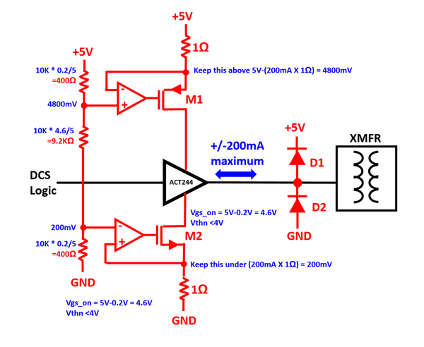
I thought it would be wise to check out the 74ACT244s directly so here they are:

Slide5

Slide6

Slide7

Slide8


The voltage swing looks pretty much the same in both the good and bad channels so I feel it's safe to say the ACT244s are working fine. From my understanding of the traces on the PCB it looks like they the 4 left channels together to form a positive output and the 4 right channels together to form a negative output, then use it differential to drive the output transformer after a filtering network. I don't understand the filtering network too well since I don't have a schematic.

Given this case I measured the ACT244s deferentially also to make sure there wasn't something the single ended monitoring wasn't capturing.

Slide9

Slide10

Slide11

Slide12

Again in differential mode both the weak and good channels have about the same voltage swing. If you zoom into the individual bits inside both look like clean square waves.


Next I traced into the output network after the ACT244 as far as I could. Again I don't have a schematic so I don't really know what's going on. If you follow the next 3 pictures I go through some type of 3 stage filter. At the output of the filter the signal is good for the good channel but weak for weak channel. I swapped all the passives between the ACT and the point where the bad signal appears (I think it's 3 series inductors) but the problem didn't move channels so it seems those surface mount devices are okay.

GOOD CHANNEL:

Slide13

Slide14

Slide15

BAD CHANNEL:

Slide16

Slide17

Slide18

So that's as far as I've gotten in troubleshooting. Not having a schematic makes troubleshooting really painful. I don't really understand exactly what this network does, and there are some discrete transistors in there so it's hard to understand exactly what's going on. Clearly something here is killing the signal swing since up to the 2nd stage the weak and good channels look identical.

We have about 11 TIUs in our club with 2/4 or 3/4 channels in this condition, that worked just a few weeks earlier. Once this happens the channel is basically unusable on the layout so I'm really trying to find answers. We find if we have a TIU with only 3/4 channels connected to the layout, then the unused channel never has this problem, this only happens to channels in use which is why we think it's related to operation (probably short circuits). Again it's hard to believe that the ACT244 isn't breaking and something in the output network is... but the measurements are what they are.


Looking for any help from the smart and way more experienced people on here...


-Adrian


Attachments

Images (17)
  • Slide2
  • Slide3
  • Slide4
  • Slide5
  • Slide6
  • Slide7
  • Slide8
  • Slide9
  • Slide10
  • Slide11
  • Slide12
  • Slide13
  • Slide14
  • Slide15
  • Slide16
  • Slide17
  • Slide18
Last edited by Adrian!

Wow, I think it's time to talk to the folks at MTH, you've delved into this farther than most.  It sure looks like something is stomping on the signal!  On a lark, have you replaced the TVS diodes?

All of us suffer with the same shortcoming, no schematics for a lot of the stuff we have to try to work on.  That's one of the pleasures of designing stuff, I have all the documentation!

gunrunnerjohn posted:

Wow, I think it's time to talk to the folks at MTH, you've delved into this farther than most.  It sure looks like something is stomping on the signal!  On a lark, have you replaced the TVS diodes?

All of us suffer with the same shortcoming, no schematics for a lot of the stuff we have to try to work on.  That's one of the pleasures of designing stuff, I have all the documentation!

Hey John,

Yeah I swapped the TVS diodes from channel to channel but the problem didn't move. I feel there's some parallel connection at the output of that network that is dragging the signal down but there's just too many discrete transistors and passives in the multi-layered board to trace it out or swap everything without screwing it up.

I'm putting a detailed package together for the guys at MTH to go over. We have a pile of TIUs (like more than 10) with the exact same problem on 2,3 or all 4 channels so I may just send some over for them to look at.

I didn't want to turn this into the reverse engineering department, I wanted to run trains, but the thing is it's really painful on our club. We shell out $1000 (5x200) to replace all the TIUs and everything is great for a week or two, and then suddenly everything stops working and they are all like this again. We've done about 3 cycles of this since January...  I just happen to be there, and happen to be a circuit designer... so it's sort of landed on my desk.

Thanks for your time to read all this stuff over and share your advice and experience. I do really appreciate it !

-Adrian

My only observation here at this point is to consider environmental issues.  Having that many failures in that short a time starts to suggest something outside the TIU is at least partly to blame.  We had one signal generator die and I replaced the ACT244, and I've had to replace a couple of TVS diodes, but that's it.  I've used the same TIU here for several years, no failures in all the derailments and power trips so far.  I use the Lionel PH180 bricks and run the TIU in active mode with power going through the TIU.

gunrunnerjohn posted:

My only observation here at this point is to consider environmental issues.  Having that many failures in that short a time starts to suggest something outside the TIU is at least partly to blame.  We had one signal generator die and I replaced the ACT244, and I've had to replace a couple of TVS diodes, but that's it.  I've used the same TIU here for several years, no failures in all the derailments and power trips so far.  I use the Lionel PH180 bricks and run the TIU in active mode with power going through the TIU.

Hi Again,

What you're describing seems pretty close to our setup. We use the PH180 bricks to power the TIUs in active mode also. Here is the wiring for part of our layout (I make drawings when I do these things) where we setup the trains in our back-room.

We have front tracks for setup and back tracks for storing trains. The front is turned on and off with a simple switch in front of the TIU, and the back is turned on and off with a switch connecting it to the front track. All the switches are DPDT so the ground and power are carried together. We have LED lighting for the track indicators. We use the same board that we buy for the passenger cars (JW&A-20100 Passenger Car LED Lighting Kit) to drive the track indicator LEDs.


.AGHR_setup_room

These particular TIUs have shown this weak output problem 3 times each on one or more channels since Jan 2017.

In terms of environment, I've looked at the 110V power and there's nothing concerning I've seen. No transients or over/under voltage.


The only thing is our guys are really really hard on their trains and the layout. We're talking an excess of 10 derailments an hour on some open days. We have MANY members that forget to turn the power off when setting up their train, and some that even slide it back and forth to get the wheels in while it's sparking and arcing the whole time (like a good 5-10 seconds of awfulness).  When you think of model trains you tend to think of older users that go slowly with care.... but our club can get really wild with trains flying all over the place, sparking, colliding and derailing, 3-4 people adding or subtracting trains at the same time and so on....


Attachments

Images (1)
  • AGHR_setup_room

Getting in late on this conversation, but was it explained why there are two distinct amplitudes of bursts in a "good" channel as shown in this scope shot - 2 high followed by 2 medium?  But in the "bad" channel they are all same low amplitude.

TIU_3

If this is scope shot is correct (not some kind of aliasing or digital scope artifact), it suggests the TIU has some kind of control of the amplitude after the 244 buffer.  One can then speculate that the transistors (looks like qty 4 SOT-23 device with "Q" silkscreen designators per network) between the 244 outputs and transformer might be involved in amplitude control. 

Based on your measurements, it seems like the amplitude on both sides of the transformer are about the same or 5-10 Volts or so.  So even if there's a 30-40V TVS on the track side, this suggests a 30-40V spike can couple "backwards" thru the transformer into the filter network when there's a track short causing a high di/dt.  Might such a spike pop a transistor? 

That said, and given the amount of time you've already spent inhaling solder fumes changing out the various chips with up to 20 legs, why not try swapping the Q's with a known good channel -  "only" 12 more connections?   I'd just try all 4 at once, but if going one at a time, I'd try to follow the traces to see which ones are electrically closer to the transformer and start with those going backwards to the 244.


Attachments

Images (1)
  • TIU_3

Do any of these trains fail??  I am surprised that the train electronics survive.  I assume tongue in cheek when you said 60 derailments in 5 minutes was typical operation on the San Diego Short Line.  But this 1 in every 10 minutes is still way over the limit.

Time to cease operating trains and establish a training program along with adult supervisors to run trains.

As far as the TIU it is possible your test which was pretty robust damaged more then just the transmit buffers.

Either your rework damaged a replacement chip or other things beyond normal repairs have been damaged.  Did you measure the 5V source, is it being dragged down.  One bad chip could effect the others by collapsing the 5V regulator source.

Did you examine the terminal connections.  Did you inspect the inductors?

I do not full understand your test regiment, so helping becomes difficult.

Example, did you have a control TIU to validate your test equipment between runs.  Did you just test one channel at a time, or did you do a destructive test on all 4 channels.

I would have ran a destructive test on Fix 1 as an example but measure all channel output.  Once I determined F1 was dead, what happened to the other channels?  Did they degrade too?  Or just Fix1 one.

My point being it is like changing several components on a car and than when it does not start, trying to figure out what caused the problem.  G

stan2004 posted:

Getting in late on this conversation, but was it explained why there are two distinct amplitudes of bursts in a "good" channel as shown in this scope shot - 2 high followed by 2 medium?  But in the "bad" channel they are all same low amplitude.

TIU_3

If this is scope shot is correct (not some kind of aliasing or digital scope artifact), it suggests the TIU has some kind of control of the amplitude after the 244 buffer.  One can then speculate that the transistors (looks like qty 4 SOT-23 device with "Q" silkscreen designators per network) between the 244 outputs and transformer might be involved in amplitude control. 

Based on your measurements, it seems like the amplitude on both sides of the transformer are about the same or 5-10 Volts or so.  So even if there's a 30-40V TVS on the track side, this suggests a 30-40V spike can couple "backwards" thru the transformer into the filter network when there's a track short causing a high di/dt.  Might such a spike pop a transistor? 

That said, and given the amount of time you've already spent inhaling solder fumes changing out the various chips with up to 20 legs, why not try swapping the Q's with a known good channel -  "only" 12 more connections?   I'd just try all 4 at once, but if going one at a time, I'd try to follow the traces to see which ones are electrically closer to the transformer and start with those going backwards to the 244.


Hey there,

I'm not too sure why there are two different amplitudes actually but that's a good observation that it isn't happening on the dead channel. The mechanism that creates the two amplitudes are the enable pins on the ACT244 device.  Sometimes both sides of the driver are enabled (+ and- complements) and sometimes just one side is enabled. I don't know the underlying purpose of why this is done though...

You're definitely right that 30-40V could breakdown one of the discrete transistors. I was going to swap those at some point, but they're really small and I can't make out if all 4 are the same type or even same channel polarity  (npn/pnp) or not. I was going to take it too school where I have a microscope this week and try.

Thanks for good suggestions!


GGG posted:

Do any of these trains fail??  I am surprised that the train electronics survive.  I assume tongue in cheek when you said 60 derailments in 5 minutes was typical operation on the San Diego Short Line.  But this 1 in every 10 minutes is still way over the limit.

Time to cease operating trains and establish a training program along with adult supervisors to run trains.

As far as the TIU it is possible your test which was pretty robust damaged more then just the transmit buffers.

Either your rework damaged a replacement chip or other things beyond normal repairs have been damaged.  Did you measure the 5V source, is it being dragged down.  One bad chip could effect the others by collapsing the 5V regulator source.

Did you examine the terminal connections.  Did you inspect the inductors?

I do not full understand your test regiment, so helping becomes difficult.

Example, did you have a control TIU to validate your test equipment between runs.  Did you just test one channel at a time, or did you do a destructive test on all 4 channels.

I would have ran a destructive test on Fix 1 as an example but measure all channel output.  Once I determined F1 was dead, what happened to the other channels?  Did they degrade too?  Or just Fix1 one.

My point being it is like changing several components on a car and than when it does not start, trying to figure out what caused the problem.  G

Hey,

as far I can tell the trains are okay. Honestly our layout is under fairly regular attack. We might have 4-5 people showing up at the same time running their trains, and the problem doesn't necessary lie with the junior members. I'm hoping if the failure we are seeing is understood I can just design around them (probably easier than telling seniors how to run their trains). The TIU with all the internal PCB waveforms above I posted yesterday is actually one of the ones from the layout, not the one I tested with the automotive relay shorting (although the symptoms are identical).

The testing exercise was to simply to establish that the condition we see in the layout is caused by short circuits. Once the new out of box test TIU was exposed to that long sequence of intentional shorts, it's condition matches the ones from the layout with the same issue in terms of waveforms at each stage on the PCB.  In that test I only shorted out fixed 2, but again we just want to confirm that short circuits are what lead us to the degraded output conditions we see in our layout. Given the similar waveforms at the output, the ACT244s, the mux and the filter stages, it seems we can be conclusive that the situation in our layout is arising from short circuit activities.

The rework was done with hot air at the temperatures and duration specified by the IC datasheet and the output waveforms look fine from all channels so I don't  think the replacement chips have an issue. The 5V is stable and the regulator is not unusually hot. I looked over the output network and nothing seems poorly connected, the series inductors all have the same DC resistances from channel to channel.

Right now with the TIU from the layout I currently have open, waveforms are good coming out of VAR1,2 but poor on FIX1,2. However the waveforms at all 4 ACT244s outputs look good (as shown above), and from this point onward the electronics are independent for all 4 channels. This means the issue must lie somewhere in the output network. My instinct says it's the discretes stan2004 was suggesting... which I hopefully will swap out this week...


gunrunnerjohn posted:

At this point, I think it's time to consider something like the PSX-AC to break the circuit instantly when there is a short.  I'm not sure why nobody else sees this level of failure, but that should go a long ways to solving the issue of having a short persist and damage something.

 I didn't know these existed or I'd have tried them already. Thanks for the suggestion, I'll do that.

stan2004 posted:

Getting in late on this conversation, but was it explained why there are two distinct amplitudes of bursts in a "good" channel as shown in this scope shot - 2 high followed by 2 medium?  But in the "bad" channel they are all same low amplitude.

TIU_3

If this is scope shot is correct (not some kind of aliasing or digital scope artifact), it suggests the TIU has some kind of control of the amplitude after the 244 buffer.  One can then speculate that the transistors (looks like qty 4 SOT-23 device with "Q" silkscreen designators per network) between the 244 outputs and transformer might be involved in amplitude control. 

Based on your measurements, it seems like the amplitude on both sides of the transformer are about the same or 5-10 Volts or so.  So even if there's a 30-40V TVS on the track side, this suggests a 30-40V spike can couple "backwards" thru the transformer into the filter network when there's a track short causing a high di/dt.  Might such a spike pop a transistor? 

That said, and given the amount of time you've already spent inhaling solder fumes changing out the various chips with up to 20 legs, why not try swapping the Q's with a known good channel -  "only" 12 more connections?   I'd just try all 4 at once, but if going one at a time, I'd try to follow the traces to see which ones are electrically closer to the transformer and start with those going backwards to the 244.


Well Stan,

You inspired me to debug further. I don't know exactly what those transistors do, but it doesn't seem too important. I took all 4 out of both the good channel and bad channel.

transistors

The good channel is still good (so that means it doesn't need any type of pull up or amplification to work and that these transistors aren't directly in the signal path),

The bad channel is still bad (so that means it's not a shorted device pulling them down).

Thanks anyways!

~Adrian


Attachments

Images (1)
  • transistors
Adrian! posted:
gunrunnerjohn posted:

At this point, I think it's time to consider something like the PSX-AC to break the circuit instantly when there is a short.  I'm not sure why nobody else sees this level of failure, but that should go a long ways to solving the issue of having a short persist and damage something.

 I didn't know these existed or I'd have tried them already. Thanks for the suggestion, I'll do that.

We trailed two PSX-AC units on one of our club lines for the past 5 months and they work great.  When a short happens you don't see a spark on the rail and the PSX-AC trips before the red light on the Z4000 comes on.  Any little mili second short will trip the breaker.  A little pricy at $50 each, but if it saves train electronics and TIU's it is well worth it.  I just ordered another 10 PSX-AC units to add to the club's layout.  

Bob D

gunrunnerjohn posted:

I think that's the long term solution to this issue.  If I had this kind of problem, I'd be going for them.

rad400 posted:
Adrian! posted:
gunrunnerjohn posted:

At this point, I think it's time to consider something like the PSX-AC to break the circuit instantly when there is a short.  I'm not sure why nobody else sees this level of failure, but that should go a long ways to solving the issue of having a short persist and damage something.

 I didn't know these existed or I'd have tried them already. Thanks for the suggestion, I'll do that.

We trailed two PSX-AC units on one of our club lines for the past 5 months and they work great.  When a short happens you don't see a spark on the rail and the PSX-AC trips before the red light on the Z4000 comes on.  Any little mili second short will trip the breaker.  A little pricy at $50 each, but if it saves train electronics and TIU's it is well worth it.  I just ordered another 10 PSX-AC units to add to the club's layout.  

Bob D

Oh I'm already convinced two posts ago this should work. rad400, Where did you order them from?

(So I can go empty their stock)

However, the theorist in me wants to figure out why the TIU failed and how, even if there's a solution to preventing it...


gunrunnerjohn posted:

I think that's the long term solution to this issue.  If I had this kind of problem, I'd be going for them.

So In terms of action plan I'm basically thinking this.... Move the TIUs to passive mode, power the track by the PH180. So the track has one set of wires to the brick and one set to the TIU output. Insert that PSX-AC module between the brick and the track with the trip on the hot side.

Would I need to choke off the PSX-AC/brick from the track so the 3.7MHz DCS doesn't flow in there and see load? (like 20-100uH inductor or so in series)?

There used to be an issue with the PSX-AC affecting the DCS signal, it's best to talk to the manufacturer, there was a capacitor that had to be removed to solve the problem.  Obviously, a 22uh choke that can handle the track current would solve the problem, just connect the TIU in passive mode on the track side of the choke, and the PSX-AC on the transformer side of the choke.

We've wired our layout using Barry's wiring suggestions . Light bulbs, terminal blocks,paired wires and the  layout run really well .

It would be very easy to put the layout in passive mode with the existing wiring.... Power to the output channels instead of the input.  WE still would have the terminal blocks etc.

I  believe keeping the existing wiring might  yield a better dcs signal in passive mode  rather than  trying to hook up passive mode something  similar to TMCC . 

I have only a small layout, but I have the PSX-ACs on the TIU inputs and they have caused no problems with DCS here. I also use the PH-180s for powering my layout using the two fixed channels on my TIU. 

Charles Ro used to carry the PSX-ACs at the best price I have seen. I got mine from Tony's Train Exchange, they are knowledgeable of the PSX-ACs. I don't know if Ro has the tech knowledge they do? Tony's was slightly more than Ro when I got mine several years ago. I have been a fan of the PSX-ACs for several years now. Tony's might be connected to DCC Specialties in some way as well, but I am not sure of that?

To add, my layout is wired per Barry's book as well, as Gregg says above. Except I have a Rev L TIU and no light bulbs, EOL terminators or filters.

Last edited by rtr12

Adrain

I put together the AC power suppression filter you had listed in your original post and got the following results from my home TIU.  I wanted to base line my results before I started checking the club's TIU's.

I measured the watch dog signal which is generated when you first apply power to the TIU as it was the easiest DCS signal to capture.  The results indicated I had an approximately 10Vpp DCS signal across the test interval which differers a little from the results in your original test of a good TIU channel.  What portion of the DCS signal did you test?  

Not sure if I was doing something different from your test, but wanted to compare and get your thoughts.

Bob D


DCS watch dog sig


Attachments

Images (1)
  • DCS watch dog sig
rad400 posted:

Adrain

I put together the AC power suppression filter you had listed in your original post and got the following results from my home TIU.  I wanted to base line my results before I started checking the club's TIU's.

I measured the watch dog signal which is generated when you first apply power to the TIU as it was the easiest DCS signal to capture.  The results indicated I had an approximately 10Vpp DCS signal across the test interval which differers a little from the results in your original test of a good TIU channel.  What portion of the DCS signal did you test?  

Not sure if I was doing something different from your test, but wanted to compare and get your thoughts.

Bob D


DCS watch dog sig


What you show there is about right... but do note you're heavily under-sampled. Your scope says 200KS/s, but the DCS signal is like 3.7 MHz.  My scope is set to sample at 10 MS/s when I do these tests, which is probably the amplitude varies a little between what we're measuring. I usually test with the read function on the app, which I guess is different in terms of content than the watchdog.

You're not really looking for differences like 8V, 9V, 10V.... what you need to worry about is the 100mV ones so even at that under-samped rate you should be good to debug your setup.

Adrian! posted:
gunrunnerjohn posted:

I think that's the long term solution to this issue.  If I had this kind of problem, I'd be going for them.

So In terms of action plan I'm basically thinking this.... Move the TIUs to passive mode, power the track by the PH180. So the track has one set of wires to the brick and one set to the TIU output. Insert that PSX-AC module between the brick and the track with the trip on the hot side.

Would I need to choke off the PSX-AC/brick from the track so the 3.7MHz DCS doesn't flow in there and see load? (like 20-100uH inductor or so in series)?

The manufacture recommends to put the PSX-AC between the 18V transformer and the TIU (active mode) to prevent the power surging into the TIU and beyond.  Putting the PSX in front of the TIU should not interfere with the DCS signal which is introduced at the output of the TIU.  If the TIU is in passive mode, I would think a 22uh choke would be needed.

We also put a TVS across all of our power transformer 18V terminals.  

Adrian! posted:

However, the theorist in me wants to figure out why the TIU failed and how, even if there's a solution to preventing it...

Especially since you have 10 failed TIUs.  Sorry about what turned out to be a snipe hunt with the transistors but are there any other active components left to look at? 

If a PSX is the solution, so be it.  But if it's the di/dt thru some track or wiring inductance that generates an L di/dt voltage spike, this voltage spike will occur before the PSX trips.  So you'll still get a voltage spike as the current rapidly ramps up to whatever magnitude trips the PSX.  Of course it may be that some kind of voltage-induced breakdown is not at all what the problem is.  To wit, the initial hypothesis was some kind of sustained over-current through the AC244 was the culprit.

If passive mode is used so the di/dt spike does not occur "inside" the TIU circuit, this might have promise.  It appears that each TIU channel has high-current 31.5uH and 6 uH inductors in the power path.  These obviously must be on the TIU input side (or else it would kill the DCS signal).  So this must be performing the same task as the proposed 22uH PSX filter - and goes to the earlier discussion about how passive and active mode differ wrt the DCS signal driving the low-impedance power source.

So again as to why it failed, my next comment is to further trace the signal through the transformer and to the banana jacks.  In other words where does the 10V differential or 5V single-ended signal from the AC244 get attenuated?  Seems you can probe the transformer itself.  And since we know the TIU fixed-channels at least can operate on DC, there must be some kind of DC-blocking capacitor or the like between the transformer and the output jacks.

Last edited by stan2004

So a TIU with 4 good channels had a destructive test run on FIX 2.  What was your input power for the TIU.  Fix 1 or Aux power?  Was FIX 1 and VAR 1 and 2 powered while running test on Fix2

Some how a test on Fix 2 damaged output on Fix 1 but not the variable channels?

Why did you change all 4 Transmit buffers, and the Receiver chip?

I would have changed F2 transmit buffer and test again, then I would have Changed Fix 1 if it was still bad.  I am not sure why a damaged F2 channel also damaged F1 but not VAR1 and 2 unless you were powering F1 and 2 from the same source that was being shorted.

Again, very detailed specifics of your testing and repair need to be done for outside assistance.  The volume of information is high, but the specific detailed information is low.  You can easter egg this one, or take another TIU and run the test in a more controlled manner and do the repair in a controlled and sequenced manor. 

You still have not said anything about the inductors and other connections.  I am not familiar with a rework station that you may have, but is it possible other devices where damaged when removing the buffer?

I just cut legs, remove chip, remove residual leg with solder iron, clean pads and resolder a new chip in with an iron.  I am sure a lot slower, but it works.  G

The question comes up every now and then about TIU active vs passive mode signal strength to the track.  So with the information from the above comments I did some DCS signal strength measurements to see if there is an actual difference between having a TIU in Active Vs. Passive mode.  From the preliminary results shown below, the DCS Active mode provided a stronger DCS signal to the track.  As a sample, I used the "Watch Dog" signal which is generated at power on and the "Read" signal.  

Has anyone else seen or can confirm these results?   

Bob D


Active mode  - "Watch Dog" Signal

DS1Z_QuickPrint13


Passive mode - "Watch Dog" Signal

DS1Z_QuickPrint4


Active Mode - "Read" signal

DS1Z_QuickPrint11


Passive Mode -" Read" signal

DS1Z_QuickPrint5


Attachments

Images (7)
  • DS1Z_QuickPrint5
  • DS1Z_QuickPrint13
  • DS1Z_QuickPrint4
  • DS1Z_QuickPrint12
  • DS1Z_QuickPrint11
  • DS1Z_QuickPrint5
  • DS1Z_QuickPrint11
Last edited by rad400

Add Reply

Post
The DCS Forum is sponsored by

OGR Publishing, Inc., 1310 Eastside Centre Ct, Suite 6, Mountain Home, AR 72653
800-980-OGRR (6477)
www.ogaugerr.com

×
×
×
×
Link copied to your clipboard.
×
×