


Tom, my projects are normally limited to things I can't buy as I've also found that the prices for some of this stuff is less than I can do it for.
rtr12 posted:...
However, I think Stan had the additional output loads in mond with the transistor and MOSFET versions above. Those are not CA - CC interchangeable by jumper selection, they would need separate PCBs for CA or CC. I am not sure of how much extra load they can handle, I'll have to look that up on the data sheets. (I don't know (or completely understand) all the components like Stan and GRJ do.)
If the application is to control track power, I'd go with a 10 Amp relay module...less than $1 per relay with free shipping from Asia. So, for example, 6 of the 8 relays in this 8-channel relay module could switch 10 Amps to R, Y, G or each direction.

These relays have buffers on the inputs so can fire at about 1 mA which can be supplied even by the 4070B version of your controller board. I notice the suggested other controller module can drive just under 1 Amp per output. Not clear if this would be enough to switch track power for block or traffic control.
As I understand it, the other controller module can only drive DC loads whereas the relay module can switch AC...again, if the application is to control track voltage.
Attachments
Images (1)
stan2004 posted:rtr12 posted:...
However, I think Stan had the additional output loads in mond with the transistor and MOSFET versions above. Those are not CA - CC interchangeable by jumper selection, they would need separate PCBs for CA or CC. I am not sure of how much extra load they can handle, I'll have to look that up on the data sheets. (I don't know (or completely understand) all the components like Stan and GRJ do.)
If the application is to control track power, I'd go with a 10 Amp relay module...less than $1 per relay with free shipping from Asia. So, for example, 6 of the 8 relays in this 8-channel relay module could switch 10 Amps to R, Y, G or each direction.
These relays have buffers on the inputs so can fire at about 1 mA which can be supplied even by the 4070B version of your controller board. I notice the suggested other controller module can drive just under 1 Amp per output. Not clear if this would be enough to switch track power for block or traffic control.
As I understand it, the other controller module can only drive DC loads whereas the relay module can switch AC...again, if the application is to control track voltage.
Stan is right as usual, these relay modules are great. They can be used to control your block loads, as isolators, inverters, drivers, etc. They are available in a number of configurations and they are inexpensive. The “other controller” is only DC output. I liked it in part because I could use it to trigger these relay modules and I didn’t have to worry about fanout if Murphy made my design change.
GRJ, Yes, I seem to be finding that out too. I already knew it was true for buck converters, reelays (as in Stan's post) and some other stuff, but the $15.99 traffic controller is a new one on me. The cheap ready made electronics also take all the fun out of learning about all this.
Stan, I did not realize the low 1mA activation of those relays. That is a very low power requirement. It's also amazing the prices they can sell these for! I have some older ones here and even some in use on the layout for switching power to spurs due to the problems I had with my manual switches (automotive type with LEDs). I also have some single and double relay modules that are very similar. I don't think I would try the new module I ordered for switching track power without using the relays.
Any ideas how they got to the nearly 1 amp current handling? I want to examine that module and see if I might learn something, part of the reason for the order. Probably won't learn much from it, but you never know. It does sound like a nifty gadget to have on hand and if you would like anything tested with it, just let me know and I'll try.
Shorling, Thanks and good luck with your project as well. I noticed they had some 'kits' and/or 'assembled' modules where the kit was cheaper, but not a lot less. I still need to take a closer look at all of their offerings. It's like 98 deg. here today with humidity to match, good time for doing that this afternoon.
Tom, the relay board has an external power supply requirement, so the 1ma is simply the drive needed to trigger the on-board circuit.
rtr12 posted:...
Any ideas how they got to the nearly 1 amp current handling? I want to examine that module and see if I might learn something, part of the reason for the order.

It looks like there are 6 FET devices on their board in the so-called SOT-89 surface mount package. There are hundreds of choices that can handle several Amps of current (DC) for less than 50 cents each. I previously suggested the 2N7000 FET, albeit with less current handling capability, because it has been around forever and is readily available for a nickel or so.
Attachments
Images (1)
GRJ, thanks for the clarification. I didn't think of that part...coming from the external power. Was only thinking about the requirement to activate the relay itself. I still have some trouble visualizing these things. Having one in hand is much better, it helps anyway. I warned you the learning part was still on going... ![]()
Stan, sounds like the same as what we (well you, then feeding me the ideas and how-to's that is) have been working on here with the MOSFETs and transistors. I was picturing the ready made module as being something different for some reason? I'm now thinking that it is similar to the stuff you have been helping me with, but probably using GRJ's PIC chip or other microprocessor for the ease and variety of mode selection. And if I am reading the description correctly they even have the jumpers for CA or CC operation built in. I'm looking forward to seeing this thing when it arrives.
Did you by chance see the one that works on 120vac and can handle 500 watts? They had some interesting stuff there (to me anyway). Prices seemed reasonable. I think I even saw 'made in USA' on some of them. They also have an ebay store, slightly higher prices, but most if not all had free shipping which made them actually a little less in final cost. I saw some LED flasher type modules that appeared to be using ICs, possibly similar to what you have been helping me with here. I'm tempted to order one of those as well, just for comparison. But the PIC lessons might now have preference.
I'd love to find a place that would assemble modules in the US for anything approaching the Chinese prices, I'd much rather have my stuff done here.
That would be nice. I was really surprised to see that on the module I was studying there, especially with their pricing. Wonder where they get them or maybe they do it themselves?
Hard to say, but I know I can't get any decent pricing for stuff made here! ![]()
rtr12 posted:...And if I am reading the description correctly they even have the jumpers for CA or CC operation built in.

Not sure that module has both CA vs. CC mode built-in. One bullet (shown above) suggests the LED output mode is "Common anode". There are two 2-pin shunts with a resistor next to it. My guess is that resistor is in series with the common anode. Installing the shunt shorts the resistor thereby passing full voltage to the lamps. To use LEDs, remove the shunt and the resistor limits current to LEDs. "Common anode" suggests those FETs are of the N-channel ilk.
rtr12 posted:...Did you by chance see the one that works on 120vac and can handle 500 watts?

From the photo, I'm guessing they are using 3 triacs (one per color) preceded by 3 opto-isolators to switch AC quietly (vs. clicking relays). If you needed to do this, attach a solid-state-relay (SSR) module to your output. An SSR is essentially an integrated opto-isolator and triac. Note the modules have screw-terminals on input and output so you don't need to fire up the soldering iron. Perhaps not quite as economical as the $1/relay modules but they would be quiet. You'd have to select an SSR with suitable power handling capability.

Attachments
Images (3)

GRJ, they would have to be getting them made pretty cheap to be able to sell at such low prices, unless they are making little or no profit and doing this just for fun like I am (I think that's a long shot).
Stan, I think you are exactly right about the CC-CA selection, I was not reading it correctly. Your description makes more sense too. As for the 120vac module, I won't be using it. I much prefer the low voltage stuff, less chance of electrocuting myself! ![]() I do appreciate you explaining the way everything operates and the components used. I still find all this interesting and like to learn about the different methods for doing these things. I can see where a circuit designer might even have 'too many' options. I could see myself getting stuck in this area. The solid state relays are something I might investigate too, I like the 'quiet' part and they would be interesting to experiment with and I don't have any so more stuff to order.
I do appreciate you explaining the way everything operates and the components used. I still find all this interesting and like to learn about the different methods for doing these things. I can see where a circuit designer might even have 'too many' options. I could see myself getting stuck in this area. The solid state relays are something I might investigate too, I like the 'quiet' part and they would be interesting to experiment with and I don't have any so more stuff to order. ![]()
To add even more to this... I just got an email from We_Honest including one of their traffic light controllers. Costs more than the one above ($24.99), but does some different things. I saw some of their items when I ordered my traffic lights, but I missed this one " 1 x Model Railroad 4-ways traffic signal light controller simulator 4 directions " (for searching). Also they apparently have a traffic signal with additional 'red & green' lights for pedestrians, along with the regular signals. Missed that before too. These things seem to be popping up all over the place! ![]()
stan2004 posted:Moot at this point if using screw-terminal connectors on the PCB, but that could be the Molex mini-SPOX connector:
If this is indeed the correct connector system, here's the 4-pin PCB-side vertical header from DigiKey.
I bring it up because it reminded me of another DIY PCB hack. Note the SPOX is a 2.5mm (0.098") pitch while many connectors are 2.54mm (0.1") pitch. So if you do the math on the connector pin diameters and PCB holes size, you can easily install either a 2.5mm OR a 2.54mm connector for short connectors like the 4-pin used in the traffic signal. Some free-ware/share-ware PCB layout program may not have a library of 2.5mm footprints and if not used to creating new components, it can be expedient to use an existing 2.54mm component which every layout program has.

Just for the FYI of it all and future reference, I finally got around to ordering and received these from Digikey today. I got both the male and female connectors (and terminals - still untested). The 'SPOX' connectors easily fit themselves with just a slight 'push - pull' to connect or un-connect them. The MTH plugs fit the Spox headers, but are quite snug and it takes some effort to get them apart. With the MTH to MTH connectors the 'push - pull' is snug, but much easier as the matching SPOX connectors.
Oh my, I think I really butchered that description, hope you get the idea and it is not too confusing. To sum it up, these will work with the MTH headers, but they are a very snug and tight fit that isn't as easy to disconnect as the MTH factory stuff.
Edit: You probably already knew this, but... After careful examination of the MTH connector with a magnifying glass, it had ' 5264 4 DL 18 ' in raised characters molded into the connector. Each set of characters was on a separate line, not consecutive as I have here. Doing a search at Digikey '5264' took me right to the SPOX connectors you found above. I got nothing using a couple of different combinations of the other characters in the searches.
Update: The PicKit 4 and some PIC chips have arrived (the ones GRJ listed earlier). Time to get busy and figure out how this stuff works.
The CA-CC version of the signal controller has been breadboarded and is all working just as Stan said it would. I ordered some PCBs for that version from JLCPCB.
The Galak traffic signal controller seems to be in limbo between Galak and the USPS. USPS tracking says label created July 26th, USPS awaiting item. The shipping notice said 3-5 days to arrive (from the 26th). They were a US supplier, it was ordered on July 18th. Guess tomorrow will be a good time to check on that one and see where/why it has disappeared. I have been looking forward to trying that one.
I had a US seller send me something that ended up in limbo, never did get it. They finally shipped another one. When it was at the local USPS location for ten days, I said enough is enough, send me the item or give me my money back!
I emailed them earlier, no reply so far. I might just follow your example if they don't reply with a correct solution. Thank goodness for Paypal!
Success on the Galak traffic signal controller, it's on the way. They were out of them, but are now restocked.
The PCBs for Stan's suggested transistor and MOSFET versions both work quite well. These are both very nice set ups! Still waiting on the combination CA-CC PCBs from JLC, I got sidetracked and procrastinated on ordering these.
The dual mode (CA-CC) traffic light controller PCBs arrived yesterday. Haven't had time to assemble anything, maybe this coming week. There are some errors in the PCB labeling, but the circuitry seems to be correct. When checked with a DMM everything seems to go to the right place.
I messed up while fiddling back and forth with the 4070 and 74AC86 ICs, forgot to change some resistor values and voltage labeling in the silk screens. Not a big deal, that is, unless I follow my own labeling. The drawings have been corrected and I plan to follow them instead. PCBs will only be used here for testing and experimenting. They will never escape the highly secured and secluded electronics laboratory constructed of 8" thick reinforced concrete walls! ![]()
I have one of those highly secured concrete walled labs too, but some fool put a window and door at one end. ![]()
![]()
Actually, I do have one egress window, but the lab is on the opposite side and back behind the stairway. Can't be seen from the window. I don't have one, but the door would sure be handy for getting things in and out.
Well, my door and window are at the other end of my shop as well, but I can see them if I turn around.

I do have a Window next to my computer desk and workbench.
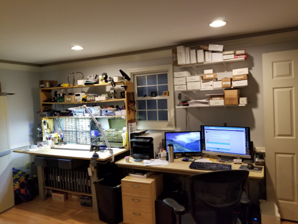
However, if I were foolish enough to try to exit there, that concrete wall would be a major impediment! ![]()
![]()
Attachments
Images (3)


Yours is much nicer looking. The natural light is nice too and the layout is also looking good in there. Your work area is much more organized and clean looking too. I seem to have an endless benchtop full of stuff with no allocated space for it. By the time space is allocated for what's there, another pile has built up with no place to go...infinite pile!
Everything here is unfinished basement, which I actually wanted. That is, until I see others with finished basements and I start thinking about finishing mine. The thought soon passes when I start thinking about having to move everything to make room to do the finishing.
From your pictures, I think I just figured out one problem I have here. Workbenches are all multi-purpose or at least trying to be. I need to make them more specialized by craft/project (or what's being done at each one).
Tom,
I actually have a couple more benches/tables as well. They're used mostly as staging areas when I have a bunch of stuff in process.
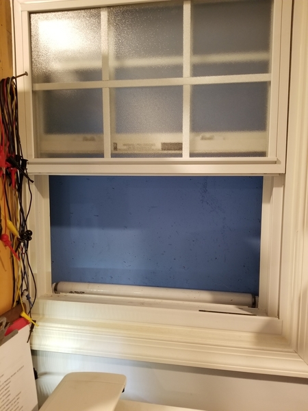
You didn't mention my spiffy concrete sunset. ![]()

Attachments
Images (2)

That sunset window was a nice touch, good idea for some added 'natural' lighting. I did like that idea there. Your staging tables even look pretty organized and cleared of massive piles!
I have a couple of tables as well, but they all have their own pile problems right now. They're pretty small though, I need some bigger ones! Maybe a couple of those fold up 6 footers would help?
I just can't seem to get completely caught up and everything situated after moving a few years ago. I'm just about to get there when someone leaves more of these electronic gizmos in the mailbox or on the front porch... ![]()
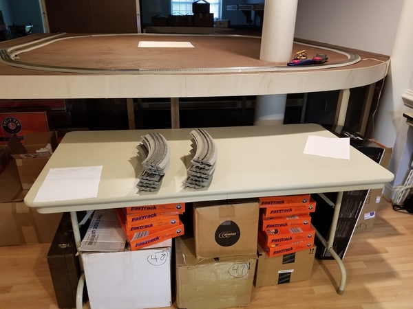
There are around 20+ locomotives stuffed in various corners in process of being upgraded or repaired, I just don't keep them all on the bench! ![]()
I don't know how you keep track of all this stuff? I could do it when I was younger, now not so much. I have to go back and re-read the things you and Stan post to help me out with projects, at times I somehow manage to get that stuff all mixed up.
Good thing I am not doing those repairs, customers would probably be receiving 'Frankenstein' engines back after I got the parts all mixed up! I'm sure you have a pretty good system of keeping track items in for repairs and upgrades.
I spend a lot of time thinking... ![]()

Attachments
Images (1)

"Sometimes I sits and thinks, and sometimes I just sits...” — A. A. Milne
In an elementary school I was working in many years ago, there was a poster of a Chimpanzee in deep thought with this caption in one of the classrooms. Been one of my favorites ever since. Some elementary school teachers have quite a sense of humor.
(Picture would have said it much better, didn't post due to recent copyright stuff...but Google finds it.)
We have a little statue of an ape holding a skull and looking at it like he's in deep thought, does that count? ![]()
Sounds like it would surely count! The quote would certainly fit that one too. Should have looked this up before, but here's a link to the chimp poster
I should have looked for this poster and bought it years ago when I first saw it, would be perfect for the secluded laboratory! ![]()
Finally got around to assembling one of the dual mode CA-CC PCBs using the 74AC86 ICs. So far it is a fail, nothing works on the traffic light outputs in either CA or CC mode. I can't seem to find anything wrong in the wiring traces on the PCB or in the schematic?
One thing I found odd: there is only about 1.1 volts on the 4017's VDD pin when the PCB is powered up. When I remove the 4017 from it's socket and power the PCB the VDD pin (on the socket only) has 5 VDC where the 4017's VDD pin should be.
I've probably goofed up something, but what? Back to 'sits and thinks' at the work bench...
Well, the 1.1 volts is a pretty large clue, are you sure nothing is in backwards? Could the socket be in the wrong orientation on the PCB?
The 1.1 volts is what I was thinking about too, but I am not sure what is drawing it down so low? I thought maybe the 5 volts was too low for the 4017, but the data sheet says it works on 3 to 15 volts. Nothing seemed obvious or to be out of place on previous checking, but I am re-checking it all now.
The 555 seems to be working as the PCB's led is blinking and adjustable with the trimmer pot.
When I got the PCBs a few days ago I rang out most of the traces on the PCB and they matched the schematic. The only thing I changed were the resistors for the traffic lights themselves, from 470 to 220 ohms, since the 74AC86's can only take 5 volts.
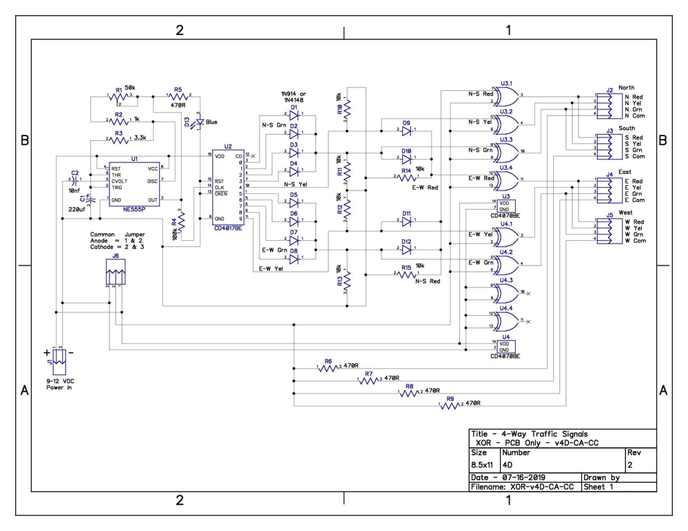
What's powering the board? Are you feeding it DC from a decent sized power supply? I'd see if the CD4017 is getting hot when it's powered, something is very wrong! Is this still the schematic you're working from? Do any of the chips get hot? How about other components?
I'm using a DC power supply, 30 VDC 5 Amp from Banggood powered by an external power supply that was listed with this item back when I got it. It was more than their minimum recommendations to get the 30 volts and 5 amps out of it, I believe I upsized it one size to be sure.
Yes, basically the same schematic except I changed the 470 ohm resistors to 220 ohm and made some cosmetic adjustments for neatness. I'll attach the most current one with the resistor value changes just to be sure. I didn't catch the resistor value errors or the suggested power supply input voltage until I got the PCBs back.
This was all working on a breadboard using the same power supply, but with a 9 or 12 volt supply voltage. I was using the CD4070 ICs instead of the 74AC86s because I had to order those and had the 4070s.
Here's the updated and latest.

I rechecked it all again and it still appears to be correct, I must be missing something? Even tried it with the 74AC86s removed, still got 1.18 volts on the 4017's VDD pin, but get 5 volts (full supply) on the VDD socket with the 4017 removed. I'm going to get out a new 4017 and try that later tonight or in the AM, was wondering if maybe something was wrong with the IC?.
Attachments
Images (1)

Did you perhaps leave the current limit set too low? From the spec sheet...
Its adjustable output current range is 0-5.000A, step by 0.001A.
I had it set to 0.100 amps, for safety, thinking that would be sufficient. I was only trying one traffic light for testing. But even with no output lights connected it gives the same 1.18 volts on VDD of the 4017.
Guess I could try turning it up to half an amp or even an amp.
That seems to be a fairly nice power supply, got their nice aluminum custom case for it also.
More current tends to localize what is drawing all the current. ![]()
Wife has me tied up short today. I'll crank up the current and go for smoke later this afternoon.
It's a mystery, but something is obviously sucking down current if it's limiting at 100ma.
gunrunnerjohn posted:More current tends to localize what is drawing all the current.
Reminds me of that diagnostic instrument that measured the field generated by a strong current on a PCB trace. A clever way to localize a fault. Can't think of the name of it...
Wife let me off early (it's Friday!)... Problem solved - Bad CD4017 IC was the culprit. I must have killed it somehow in the earlier breadboard fiddling I guess? Strange thing though, it was working on the breadboard when I unhooked and dis-assembled it all.
I tried setting my power supply to 1 amp output, still got 1.18 volts on the 4017's VDD pin. Then with no outputs connected, no jumpers, I took ALL the ICs off the PCB and still got the 1.18 volts on the 4017's VDD. Got a new 4017, plugged it in and got 4.99 volts! Put the rest of the ICs back in place, hooked up an MTH traffic light...it worked perfectly!
Life is good! ![]()
Sounds great Tom, figured you'd track it down. the old CMOS parts were pretty static sensitive, so you may have zapped in in handling. Thankfully, most of the current generation parts are actually pretty robust, and I rarely see that kind of failure anymore.
cjack posted:gunrunnerjohn posted:More current tends to localize what is drawing all the current.
Reminds me of that diagnostic instrument that measured the field generated by a strong current on a PCB trace. A clever way to localize a fault. Can't think of the name of it...
That would be an IR thermometer, just go around until you find the hot trace. ![]()
Thanks, I guess I could have zapped it during handling? So far they have been more robust as you say, but anything is possible I guess. I'll admit I am not all that careful when handling these things. Strange problem, but all is good now!
If there is any interest, here are the Diptrace and gerber files for the SN74AC86 version for anyone that wants to try making one of these. This version will operate either Common Anode or Common Cathode traffic lights. CA or CC mode is jumper selectable on the PCB. The files attached include parts lists with Digikey part numbers. I have tested this here and it works well with either CA or CC traffic lights.
On my test PCBs for the current version posted below, I had some of the parts and screw terminals a little bit too close to a couple of other components. Everything still fit in it's designated spot (some snuggly), but some of the screw terminal IDs were covered after the components were installed. In the files posted here I have tried to adjust all this to allow proper spacing, but I have not yet ordered any new PCBs with these changes.
As for the costs, the Digikey parts for one PCB add up to $14.90 and $15.77 if you want to add sockets for your IC chips, If your order qualifies for USPS First Class shipping (has to be less than 14 oz.) it will be $4.99. Any sales taxes due would also be added to the total cost. Some items have tariffs, but I think they are included in the prices given. Of course any additional applicable tariffs would also be added to the total cost.
For 5 PCBs at JLCPCB it is $2 plus $5.24 shipping for a total of $7.24. You can also get DHL 2-4 day shipping for $16.81 (5 PCBs = $18.81 total). For 10 PCBs at SEEED it is $4.90 plus $4.17 shipping for a total of $9.07. The PCBs are too large for OSHPark, 3 PCBs were $36.50 for 3 PCBs with free shipping.


Also attached is a PDF file including the above pics for download with the Diptrace files.
I also have some PCBs for the CD4070 version, identical to the one posted here but using CD4070 ICs instead of the SN74AC86 ICs. This version can run on 9-12 VDC, but have less output current to the traffic lights. This is the circuit I breadboarded for testing as I didn't have the SN74AC86 ICs at the time Stan was designing the circuit for me. These haven't yet been assembled or tested, but I plan to do that soon and see how they work. If there is any interest I can also post those files when done.
Then there are the higher current output versions using transistors or MOSFETs which also worked well in testing. However, these versions are not easily selectable between Common Anode and Common Cathode. Switching between modes here would require slightly different PCB configurations and would not be all that practical. They would be best when built for one mode or the other, not both.
Even if no one ever uses the stuff posted here, it's been a lot of fun and a good learning experience for me! And a BIG Thanks to Stan and GRJ for all the help with this!
Edit: - 09-03-2019 - There was a mistake in one of the PCB 3D components. It was only a cosmetic thing, but I wanted everything to be correct. It's now been fixed and all the files posted here have been replaced with the corrected versions.
Attachments


Tom: Nice job! I'm going to have to give DipTrace and PCB layout a try sometime. I've got it on my computer but quickly get lost in the details. I'm gonna have to give it another shot. I'm encouraged by your efforts. ![]()
DipTrace is considerably easier to use than most of the other programs I tried. One of the key features is I've found it easier to generate new parts, I tried Eagle PCB, and that was a major PITA to try to create a new part!
Thanks, Leo! As GRJ says, Diptrace is not too bad to learn. I think you will be going in no time once you get started. GRJ might even help once in a while too, if you post here about it. ![]() It took me a while to get going with Diptrace, but there was a lot of good help here that got me started and kept me going! I still struggle with the library stuff, slowly getting there.
It took me a while to get going with Diptrace, but there was a lot of good help here that got me started and kept me going! I still struggle with the library stuff, slowly getting there.
One of the hardest things for me was part selection. I don't know all the parts, names, sizes of footprints, etc. and there are a LOT of parts. Once you get a few parts selected drawing the wires are pretty easy. You sometimes have to fiddle with footprints when making the PCB, get those done before selecting 'Make PCB'. As GRJ has reminded me, use the error checking often!
Also, download some of the posted Diptrace files around here and take a look at them, that helps too.
What I'm thinking about is putting an Arduino Nano on a PCB which should just be a matter of proper spacing for the 0.10 inch headers. The Nano has parts on both sides. So the stand-offs serve a purpose.
But now I see that JLCPCB will soon be offering an SMT installation service that could change what might be possible. It may allow the Arduino to be integrated onto the PCB from raw parts. My eyesight is not good enough to attempt SMT soldering on my own. So this may be worth the extra cost.
For now, I'll concentrate on mounting the Nano on the PCB directly. It would be nice to find a Nano footprint to work with under DipTrace but what I've tried so far has not worked out. Any ideas?
Consolidated Leo posted:What I'm thinking about is putting an Arduino Nano on a PCB which should just be a matter of proper spacing for the 0.10 inch headers. The Nano has parts on both sides. So the stand-offs serve a purpose.
But now I see that JLCPCB will soon be offering an SMT installation service that could change what might be possible. It may allow the Arduino to be integrated onto the PCB from raw parts. My eyesight is not good enough to attempt SMT soldering on my own. So this may be worth the extra cost.
For now, I'll concentrate on mounting the Nano on the PCB directly. It would be nice to find a Nano footprint to work with under DipTrace but what I've tried so far has not worked out. Any ideas?
One of my nano projects that is still on a breadboard, but that I would like to get to PCB, is a 2-rail 8 block detection circuit. The nano boards I get already have the male headers on them. (You can get them for the same price as the ones with the unsoldered headers, but you have to shop for them as many sellers will sell the nano without the headers soldered. ) So I was simply going to put the two female headers on the PCB, which would allow me to swap out the nano if it ever goes bad.
I have some nano breakout boards from deek-robot that have these same female headers on the board. You can see a picture of these at the below link. How they did it was pretty much the same way I was going to do it.
https://www.amazon.com/Deek-Ro..._pdt_img_top?ie=UTF8
It seems like I have seen some Arduino footprints somewhere, just can't remember where right now? I'll do some looking around tomorrow and see if I can remember where I saw them. I'll post what I find tomorrow if anything turns up.
I saw that on JLCPCB about the assembly of the PCBs, also said starting at $7 I believe. That would be a pretty good price I think. I struggle with the SMT components as well, but I will keep practicing as I have some more here to work on.
I think I should be able to draw a schematic that attaches header pins to the rest of the circuit without the need to know about the Nano at all. Then on the PCB layout, I'd just have to make sure the spacing of the headers is correct.
Okay, whoa! My head is spinning! I ran into the DipTrace forums about Arduino Nano Libraries and recalled that sensation that hits me when I get completely overwhelmed.
Apparently you can load other parts into DipTrace by adding a library that contains the footprint and 3D renderings that you're after. And I found one that is supposed to work for the Arduino boards. That gets you into GitHub where the files are available for download. So I'll have to see if that'll work.
Also, while I was poking around on the DipTrace forum, I came across a post from someone named "gunrunnerjohn" who was looking for a JST connector library. Imagine that!
So I guess I'll just have to dive in and see if I can keep my head above water. Nothing ventured and all that...
It's no big deal to create a footprint for the Nano in DipTrace, that should be very easy. Yep, I managed to get my JST connectors installed. ![]() I've created footprints for other parts, and I've thought about the Nano as a possible candidate. When you're building your board with the Nano, consider having it above the board enough to put components under it, that makes for a more compact assembly.
I've created footprints for other parts, and I've thought about the Nano as a possible candidate. When you're building your board with the Nano, consider having it above the board enough to put components under it, that makes for a more compact assembly.
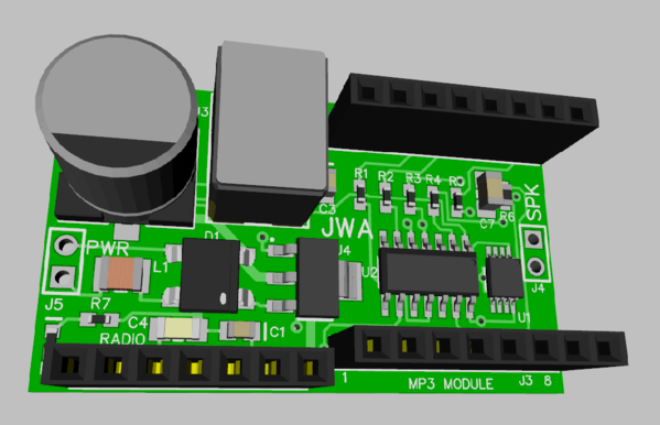
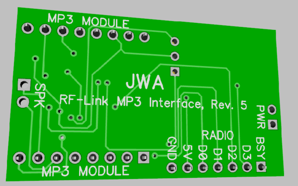
Here's an MP3 module that accepts an RF receiver on the left, and an MP3 module plugs into the headers on the right. My circuit provides power and has a uP that converts the radio data to commands for the MP3 module. By mounting all the components on the top, I was able to make it easy to mount the board using DS foam tape. No reason not to have the stuff under the MP3 module. ![]()
Attachments
Images (2)


Sounds like you have it covered with GRJ and the Diptrace forums. I didn't think of those forums? I had looked at those a while back, but as you say it was somewhat overwhelming. I haven't mastered the Diptrace libraries, more work needed there. I can change footprints, but have not tried making any. GRJ is the resident expert here on all that stuff, he's way ahead of me as he is on everything else too!
I did find the Arduino items I was thinking about but it was in EasyEDA, JLC's online design program. It might be easier to make one as GRJ says, rather than try to adapt the EasyEDA patterns. I had looked at EasyEDA some time ago, but Diptrace seemed easier and more intuitive to me. I need to start learning the Diptrace libraries too, just been busy with other projects lately and haven't really tried to do anything with it. It doesn't take much to overload my tired old brain these days.
Just a FYI, but one thing I have trouble with is allowing enough space between components on the PCBs. It all looks good in the design program and when the PCB arrives it's cramped in a couple of spots. Nothing has failed to fit so far, but I had to whittle a tad off of a couple screw terminals a time or two.
I'm personally not a fan of on-line design programs, I'd rather be running it right here, not to mention sharing only what I want to share. ![]() Too many web sites have "shared" stuff that clearly wasn't supposed to be shared in recent memory, I'll stick with desktop based PCB layout.
Too many web sites have "shared" stuff that clearly wasn't supposed to be shared in recent memory, I'll stick with desktop based PCB layout.
Tom, that's where the 3D view comes in handy. If you make sure the dimensions of the parts are correct (you can tweak them), in the 3D view, they usually fit when the boards arrive. I've had issues a couple of times with hole sizes.
The nice thing about components is once you've done a bunch of boards and perhaps developed a bunch of your own parts, you don't have to do that much searching. If I want the Panasonic capacitor I use in a number of designs, I just open up that design, copy the part, and paste it into my new design. All it's characteristics come along with it.
I also like the 'run on your own PC' programs as opposed to the online ones. Desktop based is the only way to go for me too.
I have been using the 3D stuff more. I have learned how to add footprints to the stuff that doesn't have it, but I need to work on the 'design your own' features a lot more. I'm pretty much at a loss in that department. I need to take the time to read up on the library stuff and figure out how to do it. That's not one of my favorite things to do so I procrastinate... I would like to get setup like you are someday with known parts and a personal library of them to choose from. The other projects we have been working on have kept me pretty busy lately. That and the wife's chores and Dr's appointments etc. Thank goodness for retirement!
I got some JLC stuff in the mail today which I think is the PBW PCBs, finally! If I get caught up there I think that will clear the queue somewhat. I've also received that nice new Hantek item to get going as soon as I clear a spot for it on the bench. Some rearranging required... more RTFM and learning there too...but I think that one will be more fun and exciting. ![]()
If you get to doing more sophisticated electronic projects, you'll wonder how you ever worked without a 'scope.
I've been looking at the combo 'scope and logic analyzer units. I really miss having a logic analyzer for some of the circuits that have lots of "moving" parts. When I was designing video boards, the logic analyzer was incredibly useful to see how my logic was working. This was long before we had microprocessors fast enough to do video processing, it was all LSI and discrete logic.
I think I am a ways off for that one, the irons I have in the fire now should keep me busy for quite a while I think. I read a little of the scope manual, but I have a lot left to learn there. I get a bit overloaded with info and have to go back and re-read some of that stuff a time or two. Then I still miss some of it...just hoping to NOT fill the secluded laboratory with 'scope smoke' right out of the gates!
I'll take a look at some of the scope/logic analyzers though, just so I know what they are. ![]()
Thanks fellas for the advice.
I am skimming through the DipTrace tutorial and Help system to try and get a handle on this program. Although my career was in programming, I'm more familiar with compilers and databases than with running mouse driven programs. I'll get it eventually.
I'm using the freeware version as I think that will be adequate for my intended design work.
I'm going to have to read through the beginning of this thread again to find out how we arrived at this point in our discussion. Maybe I should start a new topic; Help with DipTrace. I'm sure I'm going to need more advice.
The free version should be fine, I think it's good for like 300 points, component connections or what ever they are called. I think that is what most of us here are using. I'll be glad to help where I can, but GRJ is way ahead of me in this department (as well as all the other departments around here).
Actually, I think I hijacked this thread form a few years ago? I could have sworn there was another traffic light thread, but this is all I could find. I think Kris started it originally for his Knight Rider project. He was also in the other thread too, as I recall. The one I can't find.
For anyone interested in ordering some PCBs, I recently sampled a few PCB manufacturers to compare pricing. The sample PCB I used was from the 4-way traffic signal project. I've added some components to it, opto-isolator, bridge rectifier, capacitor and voltage regulator, in addition to existing components. The final PCB ended up being fairly large, about 80mm x 68mm (approx. 3-1/4" x 2-3/4").
| PCB Estimated Costs | |||||||
| Qty | PCB Supplier | PCB Size (2 Layer Std) | Cost | Shipping | Totals | Cost Per PCB | |
| 5 * | JLCPCB - 5 PCBs | 80mm x 68.1mm | $2.00 | $5.24 | ** | $7.24 | $1.45 |
| 10 | JLCPCB - 10 PCBs | 80mm x 68.1mm | $5.00 | $6.48 | *** | $11.48 | $1.15 |
| 10 | SEEED - 10 PCBs | 80mm x 68.1mm | $3.92 | $11.08 | $15.00 | $1.50 | |
| 10 | PCBWAY - 10 PCBs | 80mm x 68.1mm | $5.00 | $8.00 | $13.00 | $1.30 | |
| 5 * | ALLPCB - 5 PCBs | 80mm x 68.1mm | $13.00 | $10.00 | $23.00 | $4.60 | |
| 10 | ALLPCB - 10 PCBs | 80mm x 68.1mm | $14.00 | $12.00 | $26.00 | $2.60 | |
| 3 | OSHPark - 3 PCBs | 80mm x 68.1mm | $42.40 | $0.00 | $42.40 | $14.13 | |
| 12 | OSHPark - 12 PCBs | 80mm x 68.1mm | $169.60 | $0.00 | $169.60 | $14.13 |
* = JLCPCB and ALLPCB are 5 PCBs as default quantity. ** = Best - Per PCB for 5. *** = Best - Per PCB for 10.
Some places offered a default quantity of 5 PCBs and others offered 10. I upped the quantities to 10 at the places using 5 as their default for fair comparison with the others. As far as I could determine, OSHPark offers PCB quantities in increments of 3 only. All are located in Asia except OSHPark, which is located in the US (I believe they also have their PCBs made in the US).
I have used OSHPark, JLCPCB and SEEED, all had very good quality PCBs and I have had good results with them. I have not used PCBWay or ALLPCB. Shipping times from the suppliers I have used are all similar and will usually take 2-3 weeks when using their standard shipping, their least expensive shipping method. The Asian suppliers also offer PCBs in several colors at no extra cost, but choosing a non-standard color adds 3-4 days to the PCB manufacturing process. They also offer Expedited DHL (or other carriers) shipping at additional cost over their standard shipping rates.
I have used JLCPCB the most. JLCs shipping prices seem to sometimes vary a bit with different quantities. I have also noticed that sometimes selecting greater quantities can actually lower the pricing, so pricing seems to fluctuate as well. I have never ordered more than 20 PCBs at one time. Pricing and shipping on my lot of 20 was inline with increases in quantity prices and shipping costs shown above.
OSHPark offers free shipping as standard, and their shipping is pretty fast once they get the PCBs back from manufacturing. One thing to watch for on the Asian PCB manufacturers is shipping selections when you check out. They usually have some type of Expedited shipping selected as the default, so unless you want them faster, be sure to change that to the least expensive shipping selection.
Lastly, to be fair to OSHPark, they can be very competitive and cost much less than any of the others if you are ordering small PCBs. I didn't compare sizes to see where they became the most competitive, but I am guessing it's somewhere around one to two square inches in size. If you have small PCBs they are definitely worth checking out and can be very inexpensive at OSHPArk.
Edit: Thought of a couple more things here: Currently (as of this post) the Asian PCB makers all offer their default pricing for PCBs up to 100mm x 100mm in size. The prices start going up for anything larger.
Also, some of the Asian suppliers are offering free or discounted PCB assembly for a small quantity of PCBs, one site offered this service free for 5 PCBs. I'm not sure if this is a one time deal or what on assembly, but I suspect it might be a limited time offer to get you to try their assembly service?
I've never tried doing this and am not exactly sure how to go about it, so I didn't pursue any of the details for these services on any of the sites. However, this might be a good option if you want to use very small Surface Mount parts on your PCBs. I also believe you have to use their parts for this offer as well, but I didn't check into that either.
That's a great job summarizing the options! ![]()
BTW, some time back there was discussion about consolidating the various PCB designs...perhaps with a link to the originating threads. Do you know what became of this? I figure there are over a dozen PCB designs by now born from OGR discussion.
Stan, that would be a good post in the Documentation thread, but we'd have to have one person maintain it so they could add edits as new projects come along.
Thanks for the kind words, Stan! It could very well have been me who was talking about putting all these projects in one thread? Several times I have thought that would be a good idea as well. But somewhere along the lines I think I've lost track of some of them. I have a few saved, but I don't think I am anywhere close to having them all.
I would be willing to volunteer to try and maintain a thread of them all, that is if I can find them all. I agree with GRJ that it would be probably best if placed in the Electrical Reference Docs thread.
I'll see if I can put together a small list and post the links in a new thread. Then if anyone knows of others that are missing, just let me know and I will add it to the list.
Tom, if you start a thread, I'll see what I can add to it, when we get a decent list, we can put it in the documentation thread.
Ok. I'll get one going. I do have a few thread to add as well, but it will probably be tomorrow before I get started on it. Thanks for the assist, I need all the help I can get! ![]()
Tom I can also offer assistance to help develop the list. I think this is a really good idea.
Rod
Thanks, Rod. All help is appreciated! I just started a new thread for putting a list together as GRJ suggested. I'm still gathering links to post, some of which I'm sure you know of, but please post anything you have ready.
Here's the link: Creating a List of Electronics Projects developed on the OGR Forum
You might post names of other projects that have passed by, maybe that will spark some memory and we can include the stuff for them as well. I suggest each project have the associated files to recreate it if possible.
Ok, I have added a couple things to the new thread. Also with some more thoughts, questions, etc... One was about the associated files you mentioned here. I was originally just thinking links, but posting the files would be nice to have as well.
My only fear was if someone made changes to the files in the original thread, that might be missed? OTOH, many of these projects have been posted for a while now so updates could be unlikely?
The thread of projects by OGR Forum members has been posted to the Electrical Reference Materials thread here: Electronics Projects Developed on the OGR Forum by OGR Forum Members
All the projects from the other thread about creating the list have been added. If anyone has any more projects to add, let me know and I'll try to get them added to the main list in the Electrical Reference Material thread. Also, I probably have errors in the list somewhere, so corrections are welcome as well!
I tried to go back through the project threads and give credit to everyone involved for the different projects. No one was intentionally left out, but I probably missed someone somewhere. I'll be happy to correct that info as well, just let me know.
rtr12 posted:The thread of projects by OGR Forum members has been posted to the Electrical Reference Materials thread here: Electronics Projects Developed on the OGR Forum by OGR Forum Members
All the projects from the other thread about creating the list have been added. If anyone has any more projects to add, let me know and I'll try to get them added to the main list in the Electrical Reference Material thread. Also, I probably have errors in the list somewhere, so corrections are welcome as well!
I tried to go back through the project threads and give credit to everyone involved for the different projects. No one was intentionally left out, but I probably missed someone somewhere. I'll be happy to correct that info as well, just let me know.
Tom
FYI - Your link above points back to this 555 timer and semaphore thread
Bob
Thank You for catching that!! Should be fixed now and pointing to the correct post.
That's what I get for having multiple browser tabs all open at the same time while trying to edit things...I should have checked it after posting.
Add Reply
Sign In To Reply
