Hi
Has anyone used a 555 Timer Circuit for a Semaphore?


|
|
Hi
Has anyone used a 555 Timer Circuit for a Semaphore?
Replies sorted oldest to newest
What type/brand ?
For what end result, timed yellow?
Dave
Hi Dave
Semaphore is a Lionel from the 1970's. Got it for a song and I wanted it make it work. From some of the material I have seen it should use 555 Timer circuit as not burn out the relay. Any pointers or could you point me in right direct for more information.
Kris,
A model number would help, and you can also Google it to find more info.
As far as the 555 timer goes, I don't see the connection with the traditional semaphore unless it was used to limit on-time for a smaller display layout that might leave the train setting on the activation device for extended periods.
However, on a larger loop it could be used to hold the RED indication for a longer period after a short train passed.
These are usually used with an under-track contactor or an insulated-rail.
This document shows typical hook-up instructions Lionel #159
But look up your particular model.
Dave
Dear Dave
It is Auto matic Operating Semaphore model# 6-2151. However, I am planning I purchasing Semaphore Lionel #151 and Lionel #82. Also MTH 7 light Block Signal 30-11013.
Dear hokie71
Thanks for the reply. I have studied the suggest on the like and they look great. I let you know if I need more information.
Kris,
those timer units you see discussed (I complained about one in my last post) actually worked. Turns out I had a poor quality dc power supply and needed to add a capacitor on the output ![]() . I am using one now to power a wile coyote house so it turns off after 25 seconds.
. I am using one now to power a wile coyote house so it turns off after 25 seconds.
> Be aware that the #82 is larger Standard Gauge.
> The 7-light requires a two-position contactor or a relay to function properly.
----------
Something else you should be aware of if you have not seen these in person, you are working with three different sizes & two different gauges.
#82 is Standard Gauge, as mentioned
#15x versions are traditional O-gauge size
7-light MTH is a finer proportioned O-scale product
Dave
Hi Dave
thanks for the advise and info.
I have a traffic signal circuit using a 555 timer and a 4017 counter from a couple years ago. I got it off the internet, but had to modify it to get it to work properly. Not sure my schematic is the working model (don't remember if I updated it or not?). Might be something to play with anyway.
I have since gotten an Arduino which made the traffic lights much easier. That might also make your project easier? The traffic signal circuit I had was continuous (repetitive cycles), but maybe someone here would be able to make it a one shot device with minor modifications?
Dear Hokie 71
I read the thread about the timer units. Thanks for point me in that direction, I purchase a few of the relay times and I am going to play with them. Now I am just waiting for them to arrive.
Dear rtr12
I never though of using a Arduino for this circuit. I have read the basic information about Arduino. If you have more information I would like to learn more. Do you have a circuit in mind and the code for it?
Dear Dave
Thanks for pointing out to me that the 82 is Standard Gauge, that would have looked silly in a O gauge set up.
My Arduino circuit and code was also for traffic lights. It greatly simplified the other method using a 555 & 4017 that I was fiddling with. That's all I have really fiddled with so far using an Arduino though. I have some other sensors for Arduino which I got to try and learn more, but have yet to attempt to do anything with them.
I have not tried it, but I think something similar to the traffic signal could be adapted to signaling with an input from some type of train position detector rather than just using timed sequencing for the lights. I think you could probably make it fairly simple or even more detailed either way, depending on input sensors, locations and quantities used.
HI rtr12
I am using the old fashion isolated track method, nothing fancy. No IR just the isolated track and DC relay to trigger the gates and banjo and other stuff. If I could plug something in to that and have the flashing light that would be great. Or have a Arduino that acts as a dc relay and activates flashing lights when the train cross the isolated track.
Sorry, I thought you were talking about signals, like red, yellow, green when a train passed. I may have something for flashing lights around here somewhere? It seems like that is something I have fiddled with before when I was messing with the traffic lights. So, you have 2 lights and want them to alternately flash when a train passes your isolated rail?
Hi rtr12
If you have a method for the traffic lights I would like to look at that as well. That is a few project down the road but if I need to get the part I can order them now. Since RS is more or less out of business you just can not go to them and get the parts that you are missing.
Try this for your traffic lights.
Hi rtr12
If you have a method for the traffic lights I would like to look at that as well. That is a few project down the road but if I need to get the part I can order them now. Since RS is more or less out of business you just can not go to them and get the parts that you are missing.
The traffic signals gunrunnerjohn posted are the same as mine. I will check to make sure. I believe that is the working model as well. I will look for the flasher this afternoon. The one Bobby Ogage posted it probably a good one from Dale H, but the picture of the schematic is missing?
I would recommend Digi-Key for your electronic parts. Very reasonable pricing and shipping. They also accept small quantity orders. I get the parts in a day or two via USPS.
Model Railroad and Misc Electronics Here's a good site for some learning, there are a lot of 555 timer circuits here and the ones I have tried have worked. Lots of good information on other things here as well. He also offers circuit boards for some of the projects he has listed.
Model Train Circuits There is an alternating flasher circuit here, among many other things of interest. I have not tried any of these circuits.
Simple LED Flasher Circuits I believe this is the one I was thinking of from my post yesterday, there is one using a 555 timer. I don't think I ever got around to trying it so far?
Here is the Arduino Traffic Signals. I don't have a wiring diagram, but It's really simple. I set it up and took some pictures. Here is the code, I will post the Arduino file and pictures below.
The resistors used on the Arduino breadboard are 330 ohm.
------------------------------------------------------------------------------------------
/* Traffic_Signals
Operates Red. Yellow & Green LED's as Traffic Signals
This example code is in the public domain.
*/
// Pin 13 has an LED connected on most Arduino boards.
// give it a name:
int greenled = 8;
int yellowled = 9;
int redled = 10;
// the setup routine runs once when you press reset:
void setup() {
// initialize the digital pin as an output.
pinMode(greenled, OUTPUT);
pinMode(yellowled, OUTPUT);
pinMode(redled, OUTPUT);
}
// the loop routine runs over and over again forever:
void loop() {
digitalWrite(redled, LOW); // turn off red LED
digitalWrite (yellowled, LOW); // turn off yellow LED
digitalWrite(greenled, HIGH); // turn on green LED (HIGH is the voltage level)
delay(10000); // green LED for 15 seconds
digitalWrite(greenled, LOW); // turn off green LED by making the voltage LOW
digitalWrite(yellowled, HIGH); // turn on yellow LED
delay(2500); // wait 5 seconds
digitalWrite(yellowled, LOW); // turn off yellow LED
digitalWrite(redled, HIGH); // turn on red LED
delay (10000); // wait 15 secongs
}


Dear gentleman
Thank you so much for all the information.
Bobby Ogage I have been talking to Dale H via e-mail. Here is the one who gave me the information on the wig wag circuit. But I still thank you for your time and look forward on your advise.
John I know I always can count on you to whip out scheme in no time, if you do not have we know we are all in trouble. After studying it I have some question in regards to the values of the ohms and 12 VDC power supply.
rtr12 Wow that is a lot of information to study, thanks I will look it over. I like your Arduino Traffic Signals layout. Let study that as well. Thanks for the links for the electronics.
Dear John
What is the watt value for the ohms?
In regards to the cap what is the Voltage value? is there a + or -?
The DC 12 V power supply how many amps?
Which 4017B Digitech has over 35 of them listed?
Also which 1N914?
Thanks in advance.
Kris
The power supply will probably be no more then 100ma to run this, it's basically lighting eight LED's and since they're parallel/serial, you'll have maybe 60-70ma for the LED's. The rest of the circuit doesn't take much power at all.
The IN914 would be the standard axial lead one, and the 4017B would be the DIP package.
I'm not sure what cap you're asking about.
Here are the parts I used to make the traffic light circuit. I did this all on a bread board that I also got from Digi-Key.
Parts are all from Digi-Key, except the DC power supply which was from ebay and resistors were probably from Radio Shack. GRJ's power calculations would probably be plenty, I already had purchased a bunch of the 1 Amp power supplies on ebay.
Digi-Key
Item Digi-Key Part #
1N914 Diode - 1N914FS-ND
4017B Counter - 568-3080-5-ND
555 Timer - 296-1411-5-ND
10uf CAP - P1187-ND
1MEG Trimmer Pot - T93YB-1.0M-ND
ebay
Power Supply - AC/DC to DC Converter 1 Amp - From Ebay - Here's a link
The resistors used were all 1/4 watt.
I tried this again last night but it isn't working. My wife was talking to me the whole time so I probably have something missing or improperly connected. I will check it again later today. The 12 VAC note got me wondering, I'm sure that should be VDC. Will report back later. Arduino is definitely MUCH easier!
It certainly needs DC to power that circuit.
That note is a typo. It is definitely VDC. Also, I'm guessing probably better left coming from the output of the 555? I will delete it and fix the schematic. It's working now. Once you get all the jumpers in the right place it works.
I found a drawing that I think was the original that started it all. I don't think I was ever able to get it to work and ended up with the posted one instead. Here is a link to it
Two more questions for GRJ,
1.) It seems like on first power up both the Red and Yellow LEDs on the N/S lights come on. Turning the power supply down to 0 (not cycling power) and then back up to 12 VDC fixes the problem.
2.) On my working schematic of this I have a 100k resistor drawn in between the feed to the 1M pot and pin 14 on the 8017. This doesn't seem to make any difference in the operation of anything?
Any ideas on these? I don't remember this from fiddling with this before?
Here's a revised drawing with parts list.
Can you post the TinyCAD file for that one?
I suspect the counter is coming up with odd outputs, there is no reset with the circuit. I'd tempted to connect a .1 uf cap to the supply and reset, and a 10K resistor from the same junction to ground. That would give you a power-on reset. I think if you left it run for a spell, that would all work itself out.
Don't know why you'd need the 100k.
Thank you both for all all your help on this project.
Can you post the TinyCAD file for that one?
I suspect the counter is coming up with odd outputs, there is no reset with the circuit. I'd tempted to connect a .1 uf cap to the supply and reset, and a 10K resistor from the same junction to ground. That would give you a power-on reset. I think if you left it run for a spell, that would all work itself out.
Don't know why you'd need the 100k.
Certainly, here it is.
I will try letting it set for a while and then add the new cap and resistor and see what happens.
It was a couple of years ago I was fiddling with this and I have no idea what the 100k was there for? I don't remember the two N/S LEDs on start up either, it was all working before, or so I was thinking?
GRJ, one more question for the cap & 10k, which reset? Pin 4 on the 555 or Pin 15 on the 8017? I was thinking the 555, but now I'm not sure?
Thank you both for all all your help on this project.
You are welcome.
Dear rtr12
Which bread board did you get from Digikey?
The 4017 has a quirk where it can power up in an "illegal" state which probably explains the unusual LED combination you describe. As the datasheet says,
Breadboard I got was a Digi-Key part #438-1048-ND
Thank you stan2004, will give it a try. I thought 555 at first, then was thinking 4017, then was totally unsure as the 4017 reset pin was going to the negative side?
Ok, tried it and it works so far, if I got it right (no fire or smoke anyway). Of course it wasn't acting up when I went back to change things. Here's a revised diagram, if you see any mistakes please let me know. I had a ceramic cap that I used here, no idea where it came from, probably ebay? I just picked one from Digi-Key to add to the parts list.
The 4017 has a so-called "active high" reset which means you briefly apply a positive supply voltage level signal. That's what GRJ's suggestion does. When you initially apply power the capacitor is discharged so there's no voltage across it. Hence the 4017 reset pin sees 12V and the chip resets (and clears any illegal states). Then the capacitor starts charging via the resistor so the 4017 reset pin soon sees a low-voltage on its reset pin causing the chip to exit the reset condition, and it starts counting based on the clock pulses from the 555.
The 555 has a so-called "active low" reset which means you briefly apply a low level (i.e., ground) signal to reset it. So in you schematic, this pin is connected "high" and the 555 is never in the reset condition.
Typically, in schematic drawings, you indicate an active-low pin by either designating the pin name with a bar over it or by inserting a small circle on the schematic symbol of that pin:


stan2004, I think I fixed the schematic per your post (555 pin 4) and re-added it above. I am not sure I am even using the right symbols with TinyCad about half the time, so I appreciate all the tips.
I see you sorted out the reset. Like I said, it could "count" it's way out of the oddity, or you could add the components so that it comes up reset every time from power-on. There should be no reason to have to reset the 555.
The connection of the cap to the power was what threw me as the 555 reset was going to power and the 4017 was going to ground, but it seemed to be the 4017 that was acting up. Anyway, good learning experience.
After stan2004's post I went back and read the 4017 data sheet and his note about the counter getting mixed up was right on the front page. Not that I would have figured out the meaning of it all, had he not explained it prior to my reading it.
Also, I am taking it that you got the new schematic with the reset added and didn't post a revision to it, so I did get it right? ![]()
I remembered something about some of those counters starting in random states, but I didn't look at the data sheet. From your symptoms, it seemed obvious that was what was happening.
I got the schematic update, looks fine.
Perhaps stating the obvious but the 4017 Reset function (in addition to clearing any "illegal" states) puts the count back to 0 where the Q0 output is high. In your circuit this puts Red on the E-W direction.
To add some interest to your layout, if your intersection is near a grade-crossing you could have your train-detector (ITAD, isolated-rail, etc.) reset the 4017 to immediately stop E-W traffic going to the RR crossing. I don't know if there is a standard but I see this behavior on traffic signals next to RR crossings near me.
Depending on how you do block detection, it could be as simple as a 10 cent transistor and a couple resistors but no more than, say, 50 cents using an opto-isolator chip.
Good point Stan, while it's perhaps obvious to you and me, it's still worth mentioning.
I like the idea of holding it in reset when a train is passing to block traffic, that's pretty tricky. ![]()
That is a good idea, the RR crossings here do that as well. There were two intersections like this right by our old home of 35 years before we moved a little further west in 2013.
I get the idea, not sure I know how to accomplish it, but will give it a try. Something to fiddle with anyway. Will post back here with results one way or the other. Don't go away, in case I get stuck...
Thanks to both of you for all the help so far.
nvocc5,
I can't find the jumpers I got, but here is a link for some similar ones on ebay.
Male to Male breadboard jumpers
These might be easier than the ones that come with the bread board if you get one. Just thought you might like these better, I did? The one set that comes with the BB might not always be enough either?
I also found a Knight Rider (the talking car from the '80s) flasher if you are interested. Something else I have tried that I found on the internet. Probably no good for rail roads, but if you want more to play with it might be fun.
It's truly sad that the US averages about 6 collisions per day at RR crossings with several hundred fatalities each year ![]()
http://oli.org/about-us/news/collisions-casulties
The numbers seem to be on a downward trend perhaps in part because of better coordinated signaling technology. Thus, I think it's worth $1 in parts and effort to include this in your layout if appropriate.
Again, it depends on how you trigger you crossings, but a general solution would be an opto-isolator which "shorts" the capacitor when a train triggers your crossing gates/signals/flashers. I suggest the LTV-8141 opto-isolator only because GRJ showed it in one of his circuits, DigiKey sells it (64 cents qty 1), and if you're only going to "stock" one opto-isolator in your stash it's a good one to have for O-gauge applications. So by applying, say, 12V (AC or DC) to the opto-isolator thru a current-limiting resistor, the capacitor is discharged which resets the 4017 and the E-W traffic gets the red light as long as the train is present.


I had no idea there were that many collisions at crossings? The numbers have really dropped since 1981. In the 35 years we lived by those crossings I can only remember one collision with a motor vehicle. A lady ran off the road on to the track and the car got stuck. Luckily a police car came by or saw her go off the road and the policeman helped her get out of the car just before the train came through. From the report on the news it sounded like they didn't get out of there any too soon, it was a close call.
Back on track now. Thanks for the drawing revisions, I will try it out. The opto-isolator sort of looks like a relay. Would a plain old relay work there as well? I am guessing the opto-isolator is just a lot cheaper and much smaller than a relay? Never the less I am going to get some of the ones you suggest as I don't have any and have never fiddled with them. Let's see now, there must be something else I need at Digi-key while I'm there...![]()
..The opto-isolator sort of looks like a relay. Would a plain old relay work there as well? I am guessing the opto-isolator is just a lot cheaper and much smaller than a relay? Never the less I am going to get some of the ones you suggest as I don't have any and have never fiddled with them.
Right. When the opto-isolator is triggered, the transistors on the output side effectively "shorts" the capacitor like a relay would. The key is the voltage across that cap is always of the same polarity (more positive on the "top" side) so a transistor works since transistors are, in-effect, DC devices. Also, the currents involved are quite small, measured in milli-Amps, so the "puny" transistor in an opto-isolator is adequate; you do not need the Amp level switching capacity of a relay.
And, yes, if you like to fiddle with electronic parts or just want to learn more about what goes on under-the-hood you definitely need to add opto-isolators to your bag of tricks. That is, since O-gauge uses AC for track and accessory power while all the new-fangled electronics uses DC, you will frequently need to bridge that gap which, in one way of thinking, essentially means using (opto) isolators to allow the two systems to inter-operate.
Dear gentleman
This is one on the main reason I love this forum the free follow of information and great depth of knowledge that is being shared. I appreciate that you were able to help rtr12 with the traffic light problem. I also learned something new this about electronics. I will place the order with Digikey later today unless you folks want to add some else to the circuit.
Dear rtr12
Please provide with the link Knight Rider link that would be interesting to see.
Dear rtr12 and all
Since you talked about the crossing gates and accidents. The Metro North accident happened 2 miles north of where I live. It is a sad to hear that seven people lost their lives in that accident. That is the deadliest accident that Metro North has had in it history. I hope that the NTSB can learn from this accident and implement some kind of new safety system so this does not happen again in the future,
That whole circuit, including the opto for holding it in reset, would be nice to put on a circuit board. ![]()
Dear gentleman
This is one on the main reason I love this forum the free follow of information and great depth of knowledge that is being shared. I appreciate that you were able to help rtr12 with the traffic light problem. I also learned something new this about electronics. I will place the order with Digikey later today unless you folks want to add some else to the circuit.
It is a great place! This is where I learn as well, as you can see, thanks to stan2004, gunrunnerjohn and many others too.
For your parts order, I just realized I didn't have any LED's listed. I'm not sure I have ever gotten any from Digi-Key, but I am sure they should have them. I got some assortments of red, green, yellow and clear at Radio Shack quite a while back. I have gotten some at Jameco and also on ebay. They are just the plain old 5mm ones. I also have some assortments of 3mm that I think came from RS as well, but I can't remember for sure. Anyway don't forget the LED's.
It's good to have extras of all this stuff too, mine sometimes go bad. I have no idea how this happens, but usually some circuit study and moving a jumper or two will make the next ones last a lot longer. ![]() It's still good to have extras.
It's still good to have extras.
I got the Knight Rider circuit off the internet too (like the traffic signals), but it seems like it also needed a little fiddling to get working? Neither the traffic signals or the Knight rider circuits were my design (I'm not that smart). They were both found on the internet and I just fiddle with them a little to get them working and made a new diagram.
That whole circuit, including the opto for holding it in reset, would be nice to put on a circuit board. ![]()
I don't know if it had the opto-isolator in it, or the reset, but it sure seems like I have seen these in kits somewhere? Quite similar anyway. I don't know enough to do this on my own, or without you guys helping me. ![]()
I need to start keeping track of where I find these things, I will look around and see if I can find anything on them. I tried a few different variations and I couldn't get them to work as they were. After some fiddling, jumper checking and head scratching I got them to go, usually with some very minor changes.
Ok, here is a couple of the Knight Rider circuits. The jpg diagram was from the internet and I have it marked as 'Works' with no notes or scratch outs on the original print out I have. I have not tried this one again yet.
The TinyCad and pdf file I also had marked as working. This also originated on the internet, but I can't find the original file of it? Anyway, I couldn't get the original to work and changed a few things. This was also a couple years ago and unfortunately any memories of what was changed have faded. The notes are not mine, they were on the original diagram I had, but can't find now.
The bad news is I tried this one last night and so far it is not working. Will fiddle with it more today. I probably have something mis-wired, missing jumper or something? I will report back if I get it fixed and post a new diagram if there are any changes. Or will be back asking GRJ and stan2004 for more assistance. ![]()

The 4017 is just a decade counter, so the outputs will be energized one-at-a-time for each count, and it'll wrap when it counts past nine. You just have to figure out what pattern you want and arrange the diodes to match. The PDF appears to show a simple circuit that will "walk" the LED's back and forth as the counter counts.
It really did walk a couple years ago when I did this, but has since stalled out on my latest attempt yesterday. Had to be something I goofed up. ![]()
Circuit Breaker - While I was looking for the PCB's I thought I had seen for the traffic lights I found this. What do you all think of it? Looked interesting, but I don't know enough to tell anything about it. I have done some of the circuits on this website and they have all worked, so I think this guy is pretty good. He also offers PCB's for a few other items including a single traffic light. Sorry, I am easily distracted sometimes...
I'm sure it's something simple that you slipped up on. ![]()
Dear rtr12
Thanks for the information I did check out the Knight Rider stuff on the internet. I did order the Arduino Cook book and I am waiting for that to come in. I will keep in touch if you do not mind.
Sounds fine, but John and Stan will be a lot more help if something goes wrong. ![]() I tried the Knight Rider again the other day and still did not get it working. Weather is supposed to turn bad again here starting tomorrow. I will try it again and see if I can figure out what I did wrong? It worked a couple years ago? I still have not tried the one from the internet again, may try that too.
I tried the Knight Rider again the other day and still did not get it working. Weather is supposed to turn bad again here starting tomorrow. I will try it again and see if I can figure out what I did wrong? It worked a couple years ago? I still have not tried the one from the internet again, may try that too.
I also ordered some stuff from Digi-Key on Wed evening, got it today. That's a great place! Anyway, I got the Opto-isolators Stan was explaining above so will see how that goes too.
What exactly goes wrong? You could try stepping it a pulse at a time by triggering the counter directly and see where things go south. It's a pretty simple circuit, so I suspect it's something silly that's the problem.
Sharp eye Stan, that will certainly screw up the 555 circuit! ![]()
Here's the corrected files, the input file for TinyCAD and a graphics file for printing for those of you that don't have TinyCAD (which is free, FYI)
Edit: Added the missing ground that Stan so generously pointed out. ![]()

Not to be picky but I think pin 1 want to feel the love from Ground.
Duh, you're right, I was so busy moving the cap that I didn't actually look at the 555 data sheet. ![]()
I'll correct the corrected post files. ![]()
So in looking around in eBay for 555 timer modules, I came across this $1.27 (free shipping) module that has a 555 and 4017 in the same configuration as the Traffic Signal controller and the Knight Rider circuit. Yes, you'd have to be handy with the soldering iron to modify the 10 outputs with the diodes and actual LEDs but it may be a way to save some time wiring up the 555 and 4017 portion of the circuit. It probably runs fast for a traffic signal so the 1uF capacitor C1 would need to be increased. Just a thought.
http://www.ebay.com/itm/New-NE...;hash=item4ad99b4138

One more thing on the 555. Usually, if pin 7 (Discharge) is used for a basic oscillator, then the 500K pot goes to pin 8 (Vcc) rather than to pin 3 (output). But there are zillions of ways to hook up the 555 - but I'd double-check that connection.


Looks like the designers found this diagram first. ![]() There are a lot of ways to make the chip oscillate, I suspect you could wire it a ton of different ways.
There are a lot of ways to make the chip oscillate, I suspect you could wire it a ton of different ways.

Thanks for all the help guys (I need all I can get), I found the pin 1 and cap in wrong place error last night and I think my 555 timer circuit is still the culprit. Your last two posts (stan & grj) look promising. I haven't fiddled with it again yet today, but those suggestions are going to be coming up this afternoon. I must also check out the link stan posted, might have to have one or two of those. I am weak, I can't resist these things... ![]()
I think I must have copied from something else in the Tinycad drawing and never finished revising it? I was doing this about the time we started looking for a new house and moved a couple years ago. I can't find my original that I started with though.
Here's a search of Google Images for 555 Basic Oscillator Circuit, just look at a few of these and adjust your circuit until you have happiness. ![]()
So many circuits, so little time! I discovered something else a while ago.
With power on at 9vdc, I pulled 33k the resistor off of the 555 pin 3. It started working with just me holding the resistor and the other end still connected to pin 14 on the 4017. It was a bit fast, but at least I'm hot on the trail. Maybe I'll just discard the 555 and hold the resistor, a human timer...![]()
The high impedance of the counter input was just picking up the 60hz noise, same thing you see if you grab a 'scope probe.
Problem solved, working now. No more human timer required, back to the 555. Works perfect if you get everything just right. ![]()
I will fix the drawing and re-post sometime tomorrow.
Thanks to everyone for the assistance.
How close were we with the last drawing I posted? ![]()
Actually I think the only thing that was wrong was the cap on pin 1 instead of where it belonged, after pin 2 & 6. Pretty sure the real problem was my poor eyesight (cataracts they won't remove yet, maybe in a couple months) and I just had a jumper in the wrong spot and didn't (or couldn't) see it. (Not knowing what I am doing may figure into the equation as well. ![]() ) Must have checked those 555 jumpers at least a dozen times.
) Must have checked those 555 jumpers at least a dozen times.
I did 2 things yesterday, tried a new 555 chip then took all the jumpers off the 555 and re-did them. I also changed the power to the 500k pot from pin 3 directly to power supply as Stan posted above. I now think the other 555 is fine though, never saw any magic smoke. ![]()
I am going to take it all apart later and re-do it to make sure my drawing is correct now, but I think yours where you moved the cap is also correct. I will try powering the pot from pin 3 again and see what happens when I re-do it later.
If you would, post the corrected files, I keep them in the archives when this question comes up again. ![]()
I certainly will, later this evening. It might be me asking the questions again ![]()
Here is a clean file of everything, parts and revisions. For some reason the TinyCad files print funny now, won't all fit on one page. They are fine if you print from the pdf.
The Knight Rider did work with power to the pot from pin 3 of the 555, but I changed it to the main power source just to be on the safe side per Stan's post above.
In the Knight Rider Flasher, why does the 500k pot have a comment "Good starting point 4k ohm"? Sounds like a big variance. ![]()
I left a lot of adjustment room there. ![]() Actually that's the smallest one I had, 1M was the only other size I had. 4K was the only time I measured it. I'll fiddle with it some more and see if I can narrow that down a little.
Actually that's the smallest one I had, 1M was the only other size I had. 4K was the only time I measured it. I'll fiddle with it some more and see if I can narrow that down a little.
I found the comment curious when I saw the component.
FWIW, when you're drawing something like this and you know the right component is, say a 10k pot, and you're using a 500k because you have one in the junkbox, I'd still make the schematic indicate the correct value. Most folks that are going to try to duplicate it should know that you can use a larger one and simply not use the full range.
Good point, I'll remember that. Haven't had a chance to test the values again yet, but will post back with an updated diagram when I can.
Just so you don't think I forgot, my wife's father (86) is in pretty bad shape in the hospital, started very early yesterday morning, might be a while before I get back to the flashers.
Don't worry about the flashers, the family comes before play time. I wish him well and hope he makes a full recovery.
Dear rtr12
I hope that the family is well now.
Dear All
I went out and purchase the Arduino cook book and Uno R3 started broad. Since the hobby is going into electronics more and more all the time I figured the now was a good time to start. This will be my first independent project after I learned how to use the Uno R3 board.
Once you get the Arduino working, here's what you need for the project board. $4.39 and free shipping. It loads with the mini-USB and is small enough to embed in rolling stock or locomotives.

In looking, here's one even cheaper with no cable, no big loss, $2.97

Thanks for the kind words, he's home (yesterday afternoon) and doing better. May not be for long, but he is home where he wants to be. He refused further treatment (open heart surgery among other things). At 86, I would be doing the same thing he is. From my experience with others I have known, intervention like this at this age usually makes things worse and the end result is the same, possibly much sooner too.
Now I need to go order some of these latest gadgets just posted...![]()
Here are the revised flasher drawings. I think 10k was satisfactory for the trim pot. That seemed pretty slow to me. If anyone wants it slower, they can use something larger.
If you order any trimmer pots, make double sure you check the number of turns needed for full scale. Some are 20 turns and some are 220 degrees (don't ask how I know that).
Here is some Arduino code for the Knight Rider Flasher. 330 ohm resistors were used for the LEDs.
/* Knight Rider Flasher Operates LED's in Sequence as in the Knight Rider car in the TV Show
This example code is in the public domain. */
// Pin 13 has an LED connected on most Arduino boards.
// give it a name:
int redledA = 8;
int redledB = 9;
int redledC = 10;
int redledD = 11;
int redledE = 12;
int redledF = 13;
// the setup routine runs once when you press reset:
void setup() {
// initialize the digital pin as an output.
pinMode(redledA, OUTPUT);
pinMode(redledB, OUTPUT);
pinMode(redledC, OUTPUT);
pinMode(redledD, OUTPUT);
pinMode(redledE, OUTPUT);
pinMode(redledF, OUTPUT);
}
// the loop routine runs over and over again forever:
void loop() {
// Flash LED 1
digitalWrite(redledA, HIGH); // turn on red LED 1 (HIGH is voltage level)
digitalWrite(redledB, LOW); // turn off red LED 2 turn off other LED's by making voltage LOW
digitalWrite(redledC, LOW); // turn off red LED 3
digitalWrite(redledD, LOW); // turn off red LED 4
digitalWrite(redledE, LOW); // turn off red LED 5
digitalWrite(redledF, LOW); // turn off red LED 6
delay(150); // redled 1 for 150 miliseconds (1000 miliseconds = 1 second)
// Flash LED 2
digitalWrite(redledA, LOW); // turn off red LED 1
digitalWrite(redledB, HIGH); // turn on red LED 2
digitalWrite(redledC, LOW); // turn off red LED 3
digitalWrite(redledD, LOW); // turn off red LED 4
digitalWrite(redledE, LOW); // turn off red LED 5
digitalWrite(redledF, LOW); // turn off red LED 6
delay(75); // redled 2 for 75 miliseconds
// Flash LED 3
digitalWrite(redledA, LOW); // turn off red LED 1
digitalWrite(redledB, LOW); // turn off red LED 2
digitalWrite(redledC, HIGH); // turn on red LED 3
digitalWrite(redledD, LOW); // turn off red LED 4
digitalWrite(redledE, LOW); // turn off red LED 5
digitalWrite(redledF, LOW); // turn off red LED 6
delay(75); // redled 3 for 75 miliseconds
// Flash LED 4
digitalWrite(redledA, LOW); // turn off red LED 1
digitalWrite(redledB, LOW); // turn off red LED 2
digitalWrite(redledC, LOW); // turn off red LED 3
digitalWrite(redledD, HIGH); // turn on red LED 4
digitalWrite(redledE, LOW); // turn off red LED 5
digitalWrite(redledF, LOW); // turn off red LED 6
delay(75); // redled 4 for 75 miliseconds
// Flash LED 5
digitalWrite(redledA, LOW); // turn off red LED 1
digitalWrite(redledB, LOW); // turn off red LED 2
digitalWrite(redledC, LOW); // turn off red LED 3
digitalWrite(redledD, LOW); // turn off red LED 4
digitalWrite(redledE, HIGH); // turn on red LED 5
digitalWrite(redledF, LOW); // turn off red LED 6
delay(75); // redled 5 for 75 miliseconds
// Flash LED 6
digitalWrite(redledA, LOW); // turn off red LED 1
digitalWrite(redledB, LOW); // turn off red LED 2
digitalWrite(redledC, LOW); // turn off red LED 3
digitalWrite(redledD, LOW); // turn off red LED 4
digitalWrite(redledE, LOW); // turn off red LED 5
digitalWrite(redledF, HIGH); // turn on red LED 6
delay(150); // redled 6 for 150 miliseconds
// Flash LED 5 - Reverse Direction
digitalWrite(redledA, LOW); // turn off red LED 1
digitalWrite(redledB, LOW); // turn off red LED 2
digitalWrite(redledC, LOW); // turn off red LED 3
digitalWrite(redledD, LOW); // turn off red LED 4
digitalWrite(redledE, HIGH); // turn on red LED 5
digitalWrite(redledF, LOW); // turn off red LED 6
delay(75); // redled 5 for 75 miliseconds
// Flash LED 4
digitalWrite(redledA, LOW); // turn off red LED 1
digitalWrite(redledB, LOW); // turn off red LED 2
digitalWrite(redledC, LOW); // turn off red LED 3
digitalWrite(redledD, HIGH); // turn on red LED 4
digitalWrite(redledE, LOW); // turn off red LED 5
digitalWrite(redledF, LOW); // turn off red LED 6
delay(75); // redled 4 for 75 miliseconds
// Flash LED 3
digitalWrite(redledA, LOW); // turn off red LED 1
digitalWrite(redledB, LOW); // turn off red LED 2
digitalWrite(redledC, HIGH); // turn on red LED 3
digitalWrite(redledD, LOW); // turn off red LED 4
digitalWrite(redledE, LOW); // turn off red LED 5
digitalWrite(redledF, LOW); // turn off red LED 6
delay(75); // redled 3 for 75 miliseconds
// Flash LED 2
digitalWrite(redledA, LOW); // turn off red LED 1
digitalWrite(redledB, HIGH); // turn on red LED 2
digitalWrite(redledC, LOW); // turn off red LED 3
digitalWrite(redledD, LOW); // turn off red LED 4
digitalWrite(redledE, LOW); // turn off red LED 5
digitalWrite(redledF, LOW); // turn off red LED 6
delay(75); // redled 2 for 75 miliseconds
// Flash LED 1 Go Back to Top - ReStart
}
HI rtr12
Sorry to hear about the father in law. I hope is is resting comfortably and in good spirits.
Dear rtr12
Thanks for the code. I just got the Arduino starter kit yesterday and I am going to start playing with it.
Dear John
Thanks for the information about the Arduino nano. I ordered one of them and I am waiting for it to arrive.
Thanks, I was just over there this morning, my wife is staying with him until Thursday when her sister relieves her. He is doing pretty good for his condition. The hospital got us in touch with Hospice and they are great, got all the stuff he needs, hospital bed, walker, oxygen, etc. They make it all very easy. They really are a lot of help during times like this.
Let me know if those Arduino projects work out for you. They are pretty basic. The Arduino is a lot easier than using all the IC's and component parts, at least for me anyway. There is a whole lot more you can do with the Arduino than what I have posted here.
Dear rtr12
My mother in law turned 65 last July 4th. Two weeks later she was not feeling well and three months later she had passed on of cancer. It is a tough time on the whole family. We were shocked because she was so young. We are still grieving over her passing. So I know how hard it can be on everyone. My mother in law lived in Europe and they did not has Hospice like they do here.
That was pretty fast and she was still pretty young at only 65, that would be much harder to deal with especially when it was so unexpected. Takes a long time to get over that, it's a big adjustment for everyone. Cancer can be bad too, I hope she didn't suffer with it. I am kind of surprised that Europe doesn't have something like Hospice? I thought they were way ahead of us in many things and that sure would have been one of them. Hospice is a great organization if you ever need them, I have been really impressed with them.
My father-in-law has had this condition for a few years now and he is much older, so this wasn't totally unexpected. Fortunately for him, (and the family) he has been getting around quite well up until they started trying to repair him recently. That has only made things worse.
Dear rtr12
In something Europe is ahead of us but not the whole of Europe. We were making arrangement for her to go to Hospice but there was a waiting list. I is still hard to believe that she is gone.
Kind of surprised about the waiting list too? Unfortunately it will just take a long time to make the adjustments of losing a loved one so suddenly. One has to do a lot of mental processing. My grandmother died at age 87 in 1976 and out of all my family members that are gone (including my parents), I still think about her the most.
One thing the Europeans are ahead of us on is passenger trains. I bet that would really be something to see over there. I have never been there, wanted to go when I was younger. I travelled a lot for work (4 state area around where we live), now that I'm retired I no longer want to travel since I don't have to.
I made that suggestion to slow down the eBay 555+4017 module for a traffic-light application. Aren't you using this for the Knight-Rider where the lights advance more quickly?
I suggest you apply power to the module as-is and see if the LEDs advance at a suitable speed for what your want. It appears that you have some speed adjustment with the on-board trimpot.
As for mods, for the Knight-Rider don't you want the lights sweeping back and forth? To get this effect you probably need to add some diodes after the 4017 as shown in the schematics earlier in this thread.
Dear Stan
Never mind I goofed. I am building a new Knight Rider circuit from scratch based on rtr12 design. I tried the Chinese part and did not like the way it looked and worked.
Dear rtr12
Was the February 15, 2015 9:40 PM posting of the design the final out come or was there a final revision? I already ordered the parts I was missing from Digikey. I realy want to get this project going. As Gunrunnerjohn stated "stop designing and start build it" more or less.
I believe it is with one exception. The only other change that was made (I think) was making the 500k ohm pot a 10k ohm pot per GRJ's later suggestions. I fiddles with that a little more and came up with the 10k ohm pot being a smaller range that is probably all that would be needed. The 500k ohm pot will work, it is just a bit larger range than is actually needed as GRJ pointed out. It was also all I had at the time. I will post the revised schematic here.
I believe the traffic signal schematic is correct with stan2004's suggestion of the opto- coupler relay added. I will post my current schematic of that one also just in case. Since Stan's post and the schematic revision I ordered some of the opto-couplers, but I have not tried them with this circuit and crossing gates yet.
Whatever works for you, but out of curiosity what about how it looks and works don't you like.
In any event, not that anyone else on OGR has expressed interest but I see you can also buy an un-assembled kit. This makes it a lot easier to modify the circuit to perform the traffic-light or Knight-Rider circuits since you don't have to remove tiny surface-mount components...you just don't install them in the first place!


Dear Stan
The original item for $1.27 just did not work correctly and I just gave up. I did see the other that you are suggesting. But I do not have the knowledge base you have. I will also value your expert knowledge and wisdom on this topic. I will give the new design a try and see what happens. Could you modify this design for traffic lights as well or do you suggest something else?
Kris, could you be more specific on what you mean by it not working correctly?
I see there are dozens of eBay sellers offering these modules, and while I do NOT have one myself these have been sold for a while so I've got to believe they work!
I believe you can save time using either version (assembled or kit) to build either traffic signal or Knight Rider....relative to wiring up the parts from scratch. If the eBay boards are defective or just plain wrong then all bets are off of course. But if they perform as described, the are easily modified to match what rtr12 shows in his pdf schematics.
Don't suppose you have a reference number for the kits (my email is in my profile)? The idea of having a PCB already made is too good to pass up (plus I can't resist these things). Also, I don't think you can buy just the parts alone for the kit price either? We also need to compare their schematic to the one we have been working on here...just to see how they did of course. ![]()
I found this youtube of the eBay module with how I'd think it works. Yours does not do this? The speed should be adjustable with the trimpot.
I sometimes have trouble embedding youtube so here's the link:
The problem may be that it only goes in one direction, doesn't oscillate? I have a couple of the pre-made ones above, but I don't remember exactly how they worked (been a while)? I'll hook one up and see.
Here's a sample, it is uni-directional and not bi-directional.

Search "555 4017" on eBay and you'll see the assembled (about $1.27) and kit (about $1.52) versions with free shipping for both.
I understand what you're saying about one-direction. But what I'm saying is the eBay module replaces the "core" timing (555 chip) and sequencing (4017 chip) functions. The "magic" of both applications is done with diodes (1N4148 in your schematic). To get the oscillating back-and-forth sweeping of Knight-Rider, you use the right hand part of the schematic (outside the box). To get the longer red/green timing vs. shorter yellow timing of the traffic signal, you use the right hand part of the schematic (outside the box).

I don't know the range of timing the eBay modules provide using the trimpot control so I suspect for the traffic signals you may need to change the timing capacitor. The eBay module also does not have an attachment point to force/hold the sequencing that you are considering for the opto-isolator but with the kit version it's easy to simply bend the relevant pin on the 4017 chip to attach the Reset signal (with capacitor/resistor)...or cut a printed-wire trace on the board itself to patch in the Reset signal.

Dear Stan
Here what I mean the POT does not work correctly, either damage in transit or before. It does work as a waterfall as you stated. It does not work in my scheme because the length of the board is wider than the flat car, it will hit on coming train traffic with a board that long. I was hoping that would fit but for a dollar 1.27 all is not lost. If you do not try you will never know or learn anything. The new idea is to place all the electronics in box car for the MP player by the sliding door. The electronics for the Led circuit (Knight Rider)will go in the nose of the box car. There will be two tethers one from the Caboose powering the box car and all the electronics. The other tether would power the led (Knight Rider) on the flat car. It just got to crowd in the caboose with AC/DC buck, IR remote, its own led lighting, RED, led roof lights and red side led. It looked like NYC subway car at rush hour. The box car will have the MP player, amp, speaker, DC/DC step up for the Knight Rider circuit. It is better to fail and try again then never tried at all. It is all part of the learning curve. Thank you for your patients, guidance and advise.
Thanks, Stan. I was also thinking that having the kit would allow some easier modifications if needed. All those tiny little electronic gizmos on the one I have in the video are really tiny, and pretty small too. ![]()
I think having the PCB would be a big plus though, or at least a good start at putting something together and modifying to suit one's needs as you suggest. Thank you for the search, I am going to order a few as soon as I find them.
If you want to learn a new skill, you can have a custom circuit board with all the stuff on it for $36.
I use DipTrace to generate circuit boards, it is a schematic capture and board layout package that's free for small boards. You can order small quantities of boards, basically about 15 square inches total, for $36 shipped. The smaller the board, the more you get for the price. Ordering my 1.1 x 1.2" Super-Chuffer boards when I was prototyping them, I used to get 10-12 boards on the prototype order. For the 1.1" x 2" sound board I'm working on, I got eight boards for the $36.
Here what I mean the POT does not work correctly, either damage in transit or before.
I'm assuming once you set the POT value (speed of waterfall) you won't change it. That said, didn't you buy a resistor kit with dozen of values? You could experiment by simply putting the 2 leads of a resistor into circuit-board holes of the POT until you find a suitable speed and then just solder that resistor in place of the POT. Obviously you could just buy another POT - that looks like a standard component though I don't know the DigiKey number.
It does work as a waterfall as you stated. length of the board is wider than the flat car, it will hit on coming train traffic with a board that long.
I though the car lights are mounted in the grille? I don't understand why you need to mount the board that way? I always assumed the electronics would be mounted under the flat-car and wires (7 or so) run to an LED assembly under the hood. Can you post a photo of the model car showing how you plan to mount the row of LEDs?

The new idea is to place all the electronics in box car for the MP player by the sliding door. The electronics for the Led circuit (Knight Rider)will go in the nose of the box car. There will be two tethers one from the Caboose powering the box car and all the electronics. The other tether would power the led (Knight Rider) on the flat car.
If you run a tether from the box-car to the flat-car with the LED signals this would make for a somewhat clumsy 7+ wire tether; obviously this can be done but I figured you could just run a 2-wire tether that only has DC power to the waterfall electronics circuit board.
The box car will have the MP player, amp, speaker, DC/DC step up for the Knight Rider circuit.
Did you try running the waterfall circuit board at JUST 5V DC? I realize rtr12's schematic shows 9V but it should operate at 5V too. The circuit only powers one Red LED at a time and a Red LED only takes about 2V. With modern Red LEDs you don't need much current to lots of light - as stated earlier I figured you have to mount the Red LEDs separately from the circuit board so you'd need to choose and possibly buy them separately based on what would fit in the car rather than hacking up the car to fit 3mm LEDs. In other words, I'm not sure you need the DC/DC stepup module so you could just tether 5V to the flat-car.

I was also thinking that having the kit would allow some easier modifications if needed.

Right. In the case of the kit version, several things become easier if you start with the bare-board and loose parts.
1. It comes with a socket for the 4017 IC chip. The board is also "single-sided" meaning there are printed-wires only on one side. This means you could bend pin 15 of the socket so that it doesn't go thru the hole. This allows you to attach the optoisolator reset signal...and still have the ability to plug-in/take-out the IC chip.
2. No matter if used for Knight-Rider or the traffic signal, the circuit board has resistors on each 4017 output. In the schematics these resistors are not used. Instead diodes are in their place. So the same holes can be used to mount the 1N4148 diodes (100 for 99 cents on eBay with free shipping). This is an amazing coincidence. So the kit version means you don't have to bother removing resistors which in the case of the tiny surface mount parts can be a bother.
3. No matter if Knight-Rider or traffic-signal I don't think you want the LEDs mounted on the circuit board. Hence by having the kit version you just don't install them which of course means you don't have the hassle of removing them from the assembled version. And now the LED holes on the circuit board become convenient solder points to attach the wires to go to the external LEDs.
In both circuits it also appears to need a few external resistors (those shown outside the boxes in my earlier post).
I just tried the light board in the video I posted above and it works from about 2.2-2.3 vdc to 12 vdc (didn't try any higher than that). The only thing is the flash rate (waterfall) goes faster at 12 vdc at the slowest setting. As would probably be expected with increased voltage.
I have ordered a bunch of the kits and although I have some diodes, I took advantage of one of the 100 packs too. There was a different kit with the PCB laid out a little differently that I got a few of also (can one ever have too many of these things?)
And Although it's probably over my head, I am going to look at GRJ's PCB layout and design program he posted above. I think that would be neat to be able to do, just in case I ever learn enough to actually make something on my own. Probably won't happen, but as the saying goes, even a blind hog gets a piece of corn every now and then. ![]()
rtr12, are you building both the Knight-Rider and the traffic-signal projects? I'm getting myself confused on who is doing what and don't want to send you off on a wild-goose chase! That is, I know Kris has a MP3 sound module for his Knight-Rider and it's going on rolling stock so what I suggest for his application may not apply to yours.
If you're doing the traffic light I'm pretty sure you want to replace the 1uF capacitor supplied with the kit with a 10uF capacitor since the lights change every so many seconds rather than several times per second in the Knight Rider. This value difference is shown in your schematics but again if you are starting with the assembled waterfall board it may not be obvious since the capacitor is one of those surface mount parts too small to have its value printed on it.
Hi Stan
It can get really confusing very fast. The victim for the Knight Rider is a Hotwheels 1:43 scale car. I can not open the hood, I was thinking of putting the led lights under the car in the front. The Chinese waterfall will not fit under the car. See attached photos. From Rtr12 circuit it stated need a 9 volts DC but you say I use 5 VDC I will try it out and see if it works. It make sense to use less wiring with sound engineering.


rtr12, are you building both the Knight-Rider and the traffic-signal projects? I'm getting myself confused on who is doing what and don't want to send you off on a wild-goose chase! That is, I know Kris has a MP3 sound module for his Knight-Rider and it's going on rolling stock so what I suggest for his application may not apply to yours.
If you're doing the traffic light I'm pretty sure you want to replace the 1uF capacitor supplied with the kit with a 10uF capacitor since the lights change every so many seconds rather than several times per second in the Knight Rider. This value difference is shown in your schematics but again if you are starting with the assembled waterfall board it may not be obvious since the capacitor is one of those surface mount parts too small to have its value printed on it.
Sorry, I didn't mean to confuse. My writing is not always the best either, I confuse myself sometimes when re-reading things I have previously written a day or two before. The old brain goes faster than the fingers and it also abbreviates and skips a lot. ![]()
I am just getting the kits for experimenting and possible future use. I have some needs and ideas that are far from well defined like Kris's are. I am also interested in the mp3 stuff you all are working on, but I am just following along on that one, trying not to get in the way. Some of the things you and GRJ were talking about in his sound player thread were way above my pay grade.
As you stated earlier, the fact that the kits have the PCB really opens up a lot of possibilities for different things when I finally pin them down. I will probably try to make at least one of each in a few weeks when the kits arrive. I got plenty of kits just in case there is an oops somewhere during construction. ![]()
I really like fiddling with all this stuff and learn something with each new post from you and GRJ and some of the other electronics folks here. I think some of it is actually starting to stick and even make sense too.
I really do appreciate all the help you guys offer here too.
Kris, I really think Stan was suggesting that you not try to stuff the board under the hood, but rather remote the board and run wires to a smaller LED array, probably constructed from either small LED's or perhaps using fiber optic cable.
Hi Stan
It can get really confusing very fast. The victim for the Knight Rider is a Hotwheels 1:43 scale car. I can not open the hood, I was thinking of putting the led lights under the car in the front. The Chinese waterfall will not fit under the car. See attached photos. From Rtr12 circuit it stated need a 9 volts DC but you say I use 5 VDC I will try it out and see if it works. It make sense to use less wiring with sound engineering.
Hi Kris,
I did try the waterfall in your picture above at 2.2 or 2.3 vdc to 12 vdc and it worked throughout the range. I only tried it for Stan as he mentioned it should work at 5 volts in a post above and also said in an even earlier post that he didn't have one. Just trying to help out there.
I haven't tried other voltages on the other schematics above. To be honest I never even thought to try different voltages with any of them. Stan can tell by looking at the circuit (he knows what he is doing), without having to try it like I would. I can't tell by looking. Trial and error is my method for a lot of these things, unless someone here helps me with it. ![]()
Kris, how is the model assembled? I see that these go for $50 so I'd understand the reluctance to perform surgery. But it seems like the interior is molded plastic and hence at some point the chassis of the car was separate from the body. It looks like the hood was cast as part of the body so that's no fun. But it looks like the red light grille is a piece of plastic snapped in place after the fact? In other words, what I'm thinking is you can separate the body (shell) from the chassis and access the space behind the red grille. You may not be able to fit a small LED board (just the LEDs) but as GRJ notes you might be able to run a bundle of 6 fiber optic strands to driven by 6 LEDs placed below the flat car. As GRJ says I was assuming you could mount the circuit board in whatever orientation needed to fit on the flat car. The LEDs would be mounted separately (either under the hood if space is available) or elsewhere with fiber optic strands relaying the light up to the front grille.
So I guess my question is whether you are willing/able to separate the body from the under-chassis. And if so, what does the space look like behind the light grille.
Dear gentlemen
Thank you for your suggestions. I never even though of using fiber optic cable. I will take a look at car/model and see what is the story, pictures to follow shortly. Thanks again for all the help and suggestions.
Background on the picture taking, the three old though it was my toy and want me to share it so he could play with it. Also the wife saw the suggested retail price and gave me a dirty look I will never forget. I had a Lucy moment had a lot of explaining to do with both them. So if the pictures come slowly you know why.
Dear Gentlemen
Here are the picture you have requested. The bottom of the car comes off with two screws. However the grill where the led should go is made of metal. There is no plastic to hook up the leds. It is space molded in the car body and painted red. Also there is a stud mount in the same area where the led should go. Any suggestion would greatly appreciated.


The solid metal grille makes it a challenge. Do you have tools to drill/grind such small parts? I see Aoshima made a 1:43 diecast Knight Rider that comes with an LED scanner. Over $100 so kind of pricey but perhaps you can make inquiries and someone has posted interior photos of how they did it - might give you some ideas. A simple web search amazed me on level of interest in these models including the LED scanner; in other words I'd think there are others out there who tackled the exact problem you're facing perhaps on a car-modeling forum? Here's a youtube I found showing the Aoshima LED scanner in action:
Dear Stan
I come too far and with your, GRJ and others help me to make my dream a reality to stop now. So I purchased the Aoshima with led scanner at 1:43 scale. The only way to make the Hot wheels car work is in a machine shop. I would need use of a milling machine and cut off one lay at a time from the inside of the car to make the led slot. This is time consuming, I do not have a milling machine and the possibility of damaging the car runs high. Once I get the new Knight Rider I will let you know.
From what I can tell, the Aoshima model uses 2 LR44 button batteries or 3V. One option is 3 diodes in series to lower 5V down to 3V. I'd think you only need to run a 2-wire tether between cars with the DC power to replace the batteries.
Hi Stan
Thanks! That will be the easy part of this mod. What type of diode would you suggest?
What type of diode would you suggest?
1N400x which you probably have lying around will work.
Hi Stan
Thanks for the reply. I finally got a chance to paint the caboose flat black yesterday looks sharp. Once I have two coats on I will finish the electronics and post pictures for all that interested to see. Then I will start the box car part of this project.
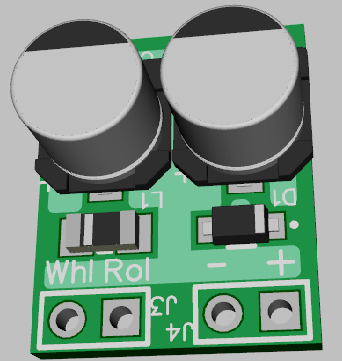
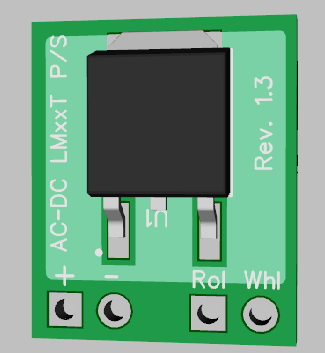
Stan2004 and GRJ, I finally got a PCB made using Diptrace and JLCPCB, using the 4-Way Traffic Signal schematic discussed in this thread. Ended up making a few changes to the original, but the assembled PCB seems to be working pretty well...no smoke so far! It's been a great learning experience as well.
This was all made possible for me with the help of GRJ designing the TIU Tester proposed by Adrian, some suggestions from Stan and GRJ's PCB design work to put it all together. Then GRJ passed the kit offering part to me since he was too busy at the time to fiddle with making TIU Tester kits for everyone that wanted one. Looking at his Diptrace files and learning how to get the PCBs made for that project gave me the incentive (and courage) to finally try learning about the entire process myself using Diptrace. Took me a while, and I still have a lot to learn, but I finally got where I could use Diptrace enough to cobble things together and get a PCB made from the files.
I started with the basic traffic signals only and then added the opto-isolator for crossing signals that Stan added toward the end of the project. I have working PCBs for the traffic signals only, but have not yet had any made with the opto-isolators. That is coming up next as soon as I breadboard the circuit so I can understand it better.
I ordered most of the PCBs from JLCPCB, they were $2 for 5 PCBs and $5.50 for shipping. Takes about 2 weeks or so to get them, which isn't bad, unless you have made a mistake and have to correct it and order more. This did happen a couple of times, but I think I have things all fixed now.
Anyway, if I could talk you two into it, I would appreciate you two looking over the new schematic and I will also post the Diptrace PCB files for your examination. Any comments/tips/pointers etc. would be much appreciated!
I posted the files in .pdf format for ease of viewing. Subject to approval from Stan & GRJ here, I'll post all the Diptrace files for anyone to use as they want.


One comment right off the bat. ![]() Modify the part in the schematic capture so the IC part number is displayed.
Modify the part in the schematic capture so the IC part number is displayed.
Ok, thanks. I'm still learning and there is lots left to learn! It's fun though, very enjoyable too.
Does this look better?

Also, I was thinking there was another thread about these traffic signals, possibly more info in it? But I can't seem to find it anywhere so I hope this is the right place to post this.

Yep, and now I know what the IC is. ![]()
rtr12 posted:...
Anyway, if I could talk you two into it, I would appreciate you two looking over the new schematic and I will also post the Diptrace PCB files for your examination. Any comments/tips/pointers etc. would be much appreciated!
It appears you're using 2mm pitch 5-pin connections to each signal head? Have you identified an inexpensive source of male-female connectors or pre-crimped cables of suitable length/gauge? Or maybe you don't plan to use connectors and just solder wires from the LEDs directly to the board?
Are you fabricating your own signal heads? That is, I see eBay seller "wehonest" has some inexpensive O-gauge LED signals...but they use the 4-wire method (R, Y, G, and a common) … as opposed to the 5-wire method.

I realize this is a hobby circuit...but the CD4017B chip is being pushed to drive a pair of LEDs in parallel. That is, one might stumble across something like this:

I suppose 10 mA output or 5 mA per LED can be quite bright but I notice that other off-the-shelf controllers advertise ability to drive up to 10 signal heads or even incandescent bulbs.

This was really an exercise in learning to make a PCB (and after a few attempts it actually works)! I have been wanting to learn that for a long time. While it would be nice actually using the PCB and circuit someday, making my own signals to use the 5 wire set up seems like a large source of frustration as it's probably not feasible to make one's own traffic signals. Especially when the ones you listed above are so readily available and affordable. I think I even have some of those around here somewhere.
I wasn't aware of the over current conditions with the 4017 ICs? Thanks for pointing that out (I need to study the data sheets more closely). That's another good point that would probably need some thought. Also I don't have a source for the 2mm pitch terminals, the ones I got are from Digikey and were not outrageously priced, but not what I would call inexpensive like the 5mm ones either. I was trying to keep the PCB as small as possible. Must be from following GRJ's projects and the way he shrinks the PCBs down so well?
You read my mind on the 4 wire problem with the premade signals. I have been thinking about that since I started trying to create the PCB, with no solution in sight so far. It's a nice thought to change the circuit to work with the 4 wire signals, much more practical. However, not sure I have the know how to do that, if it's even possible. You are right about the off the shelf controllers being much better and easier to use, which I should probably just use for any layout projects, but taking this route I never would have learned to make a PCB.
If you have any thoughts on a better IC for the above project, or any ideas on using the 4 wire ready made signals with the my newly created PCB I'd love to hear about them. All the while I was working on this I suspected that it may never actually get used on a layout anywhere, but it was really a fun project and didn't cost a great deal. Only goofed up a couple of PCB orders and the components are not too expensive.
So, it's really not a big deal if my PCB ever gets used, it's been a great learning experience! At least now I can cobble together a simple PCB using Diptrace. Although with some difficulty using the included libraries of parts and patterns and getting them all to match the components being used. I think creating my own actual circuit is a ways off yet, but maybe someday?
Thanks for your input and any other comments you might have to add are most welcome.
Tom, time to learn a little programming, that makes a lot of these projects go much smoother. Can you creating the Super-Chuffer functionality without a processor? ![]()
FYI, here's a simple little fixed DC supply I build, I shrunk it a bit and I'm waiting on it's boards. I use this whenever I need a little DC power from track power in a locomotive or rolling stock. I can use any value voltage regulator on it to obtain various power values.
I normally just encase them in a bit of heatshrink.


I'm guessing the Super Chuffer would be a real nightmare without micro controllers! Can't even imagine where to start with ICs? And I bet the the PCB would be about as large as an old 1960s color TV set if one ever did get a somewhat working prototype. That would be a challenge, at least I think it would. The 4 wire signals would be much easier with an Arduino too, at least for me.
I can do a little Arduino programming (with a lot of looking up syntax, libraries, etc.), but I am also somewhat fascinated with the IC chip methods and creating circuits with them. I'd like to learn more about all that too, probably the reason for my obsession with the traffic light circuits. C programming takes me quite a while too, but on the brighter side there is a ton of ready made programs for the Arduino stuff. The size of the Arduino boards are a problem though, can't shrink them up like you can a PCB of one's own design.
I think you are using the PIC chips for some of your projects, which seem to have endless possibilities. I have never tried any PICs so they are all new to me. From what I have seen, if I'm understanding correctly, they are programmed in assembly? If so, that's definitely over my head. I've seen a PIC Basic programming language advertised for them. Don't know much about that either, but it sounds like something more my speed. Then there is the vast selection of different PIC chips available and figuring out which one to use where...I'm lost there too.
I'm not quite up snuff for putting things on both sides of the PCB like you do either, but maybe I can get to that someday as well. The way you shrink down the size if your PCBs is a very nice feature. This is all great fun and I really enjoy puttering around with all this stuff. Maybe I will take a closer look at the PIC and Arduino type stuff? I would also like to someday check into the PIC Basic programming as I used to use Quick Basic and Microsoft Basic Pro many years ago. I used to enjoy doing that too, then Windows came along and ruined all that. I fell way behind and also kind of lost interest with Visual Basic. To me it just didn't have the same fun factor for some reason.
I write all my code for the PIC in C, no need for assembly. The Microchip MPLAB-X development environment is quite complete. The one thing you also need is something like the PICKIT3 to actually program the chips. I used the ICD3, but it's a lot more expensive.
Thanks, I'll look up the MPLAB-X and see what happens. I didn't realize PICs could be programmed in C and had always wondered how the PIC Basic programming worked as well. Guess it's time for some investigating.
rtr12 posted:...
I can do a little Arduino programming (with a lot of looking up syntax, libraries, etc.), but I am also somewhat fascinated with the IC chip methods and creating circuits with them. I'd like to learn more about all that too, probably the reason for my obsession with the traffic light circuits
...
To be sure, the Arduino, PIC, or microcontrollers of that ilk provide the ultimate in flexibility, functionality, etc.. But if the "IC chip method" is still of interest, here are some thoughts.
If you want to go the 4-wire method, you could do something like this:

The existing circuit employs a "trick" whereby the YLW or GRN in one direction simultaneously drives the RED in the other direction. This is implemented with the so-called "diode-OR" function which in this case means when either the YLW or GRN LED is on, then the opposite RED is also ON. This is shown in pink above...LEDs being diodes that happen to light up. But this requires the 5-wire implementation. If going to a 4-wire implementation, you must implement this "diode-OR" function independently which in effect means you must add 2 diodes per direction to replace the "OR" function provided by the YLW and GRN LEDs. Of course these diodes are a penny a piece so it's really about the real-estate cost of the PCB than the component cost itself.
There is the separate issue that going to a 4-wire method doubles the current requirement since you can't "double-up" on the LEDs. That is, in the original circuit with the 5-wire LED head, a single 74HC4017 output drives a YLW & RED (in series) or a YLW & GRN (in series). With a 4-wire LED head, each 74HC4017 output drives a the 2-color combination in parallel. In effect this doubles the current draw on the already stressed 74HC4017.
Additionally, from what I can tell, the 4-wire signal heads are typically common-ANODE (common +) whereas the suggested alteration above assume a common-CATHODE (common -). The wehonest 4-wire signal head is common-ANODE.

So by using 6 transistors to flip the polarity of the six LED drive signals, we solve 2 problems. 1) transistor provides adequate current to drive multiple signal heads, and 2) transistor inverts the polarity of each 74HC4017 output so that a common-ANODE signal head can be used. The transistors are 5 cents each...though it does require additional PCB real-estate.


I do know the micro controllers are much more flexible. And per GRJ's post above I just downloaded the PIC MPLAB-X IDE and do intend to look into the PIC chips too. If I ever get all this figured out a PIC might be the thing I use on or for a PCB for my actual layout. I have been interested in the PICs for sometime as well.
However, I do find the IC circuits quite fascinating and your suggestions above will be put to good use to enhance the current project. I am going to try everything you suggest. Another nice learning exercise that is just what I was hoping for here. Getting this circuit to the 4 wire operation is going to be neat! I was sure I had some of the We_Honest signals, but after looking today I can't seem to locate them? Maybe they will turn up...or I'll be ordering some more for testing.
Also, I was going to ask about the 74 series 4017s possibly having more current handling as opposed to the CD4000 series, but you read my mind there too and already answered the question. I will be ordering the 2N7000s tonight and giving this a go too. I don't suppose an NPN transistor (BC547) would suffice until I get the 2N7000s? I have a small bag of BC547s on hand already (also maybe a few 2N2222s). And as you can tell, I need to do some serious data sheet study as well...if I just knew what all the data meant? Some I get, but some is not well understood to me.
Thanks to you and to GRJ for all the help and patience! It is truly appreciated and I'm even finally learning a thing or two!
Yes, the 74HC series has improved output current compared to the CD4000 series in an apples-to-apples comparison. I don't know when the original 4017 design you found came out, but I figure the CD4017 was used because of its higher operating voltage range which is needed to drive the GRN & RED LED in series. The ~3V of the GRN LED and the ~2V of the RED LED would be pushing the output voltage capability of a 74 series device which has a nominal 5V operation. Yes, you can operate 74HC devices at 5.5V which might be enough output voltage but now you're rolling the dice. The CD4000 series operates to 15V or more.
But the real issue is you want to drive a 4-wire common-anode signal head. So you need to invert 6 signals. Any common-sense signal inversion method would provide additional current drive capability for "free". I suggest the 2N7000 transistor since that's what I found on eBay for cheap (5 cents each). I suggested a FET since this means you don't need the additional overhead (PCB real-estate) of a resistor in the input. You could use your BC547 or any other NPN switching transistor like the 2N2222... just insert a ~10K resistor on the input.

Note that when inserting the inverting-buffering transistors, the "common" wire from each signal head now goes to the + side of the power source via a resistor. If using 12V DC, and driving 2V-3V LEDs, that's a 9V-10V DC drop. So if driving each LED at 5 mA, that would be a 10V / 5mA = ~2K resistor. If driving 2 signal heads in parallel (as drawn in the original design) that would be 10 mA or ~1K resistor. Adjust resistor value for desired brightness.

I hadn't thought of the lower voltage on the 74 series. I have had that 4017 circuit for several years (from at least 2012 or so, found on the internet somewhere but I now don't remember where?), so I imagine it goes back a ways. As I recall it didn't work as I found it, but I forgot what I did to get it going? Got the data sheets now, but haven't yet studied them. I think I'll start printing them out so they are handy for easy reference, then maybe some more of the info will stick.
As an aside here, I did read a book on components over the winter and it was pretty informative. But there was a lot of info to remember in there. Can't remember the title off hand, but it was a set of 3 volumes and written so I could understand most of it. Just remembering it all is a problem. It was pretty informative and covered many components.
I ordered some of the 2N7000s, got them from a US seller so I should have them next week...got a little anxious here. They were a little more, maybe a little over 10 cents or so each, but the shipping was also free and much faster. While waiting, I think I'll try the BC547s following your recommendations. Maybe I will this all figured out by the time the MOSFETs arrive. Now if I could just find my 4 wire signals...
Thanks again for all your help and suggestions.
Oops. There is a problem with my recommended inverting circuit.

I thought I was saving you a resistor per inverter-buffer by using a FET. But this only works if directly driven by a digital gate like the CD4017. Instead, in this design there are diodes in the path. So bottom line is you do need a resistor paired with each transistor when you use an N-FET or an NPN. It's just the resistor is hooked up different depending on the method. Sorry for the misdirection.
For driving a few LEDs per transistor as in this case, either method works equally well. If you were going to drive heavier loads I'd suggest the FET method which is more efficient albeit a few cents more per buffer.

Thanks Stan,
Just printed out your drawings above and was studying them to modify my wiring diagrams. I'll still be using the FETs when they arrive and the added resistor isn't a problem, but thanks for catching that. I'm sure I would not have noticed until something went wrong somewhere. But, I always order extra components just in case of any unintended smoke releases that may arise. So far so good though, no smoke! I will post back with my results, or maybe more questions first.
Stan, I think I may have it re-worked with the BC547s (MOSFETs next). Here's the revised schematic, if I got everything in the proper place (including the wires). I couldn't get the transistor symbol to cooperate as far as orientation goes, so I changed the CBE designations to match your examples. And as usual, any further input welcome (and wanted ![]() ).
).
If I got this correct, that really reduced the output wiring. Makes me feel like I missed something...![]()


Curious your choice to use two 6-pin connectors, and two 2-pin connectors for the 16 total connections. This means you're doubling up on the common wires - N-S common and E-W common have 2 wires to each PCB terminal. I'm not saying this is wrong or won't work - but perhaps unconventional.
It just seems you have 4-wires coming from each wehonest signal head and IMO you'd want those 4-wires going to a single 4-terminal connector on the board. I don't know if there are economical 2mm pitch screw-terminals available but on eBay you can get 2.54mm (0.1") 4-pole screw terminals for 40 cents each from a US seller...a little cheaper if you can wait for Asia.

I don't know the gauge of wiring coming from the signal heads. Screw terminals like this don't like really fine wires in terms of clamping down to make a reliable connection...but you can always "fold" the stripped wire ends back on itself to essentially double up the diameter of the wire to give more clamping area.

Thanks again Stan, I see my error now that you have pointed it out. I guess it was old thinking carried over from the previous circuit. Back to the drawing board. Let me try this again and I will repost. The terminals you listed also look good, that's a good price compared to Digikey. I better order a few!
I'd jump right to the FET's, they'll do all you want to do and aren't any more complicated to wire in than the transistors.
I do plan to use the FETs, but they are still on order and I don't have them yet. I was only going to try this out with the transistors I do have on hand and then swap them out to the FETs when they arrive. Was thinking it shouldn't be too hard to swap them out and redo the circuit once I had the basic stuff in place. I won't be trying any PCBs until I get the FETs. And the way things are going today, it'll probably take me until the FETs arrive to get it working...it also keeps me busy and off the streets!
You're too easy, it takes a bit more to keep me off the streets. ![]()
![]()
I'm easy, but I ain't cheap! ![]() Some slacking in old age is a big factor too.
Some slacking in old age is a big factor too.
I think I have the corrections made, time for a look to see what I have screwed up this time (before posting). Whatever it is, I'll probably miss it again though...
Ok, I have another schematic to look at. I got myself confused a few times re-doing this (sometimes that's pretty easy for me). Hopefully it isn't too far off this time and I'm at least getting closer.


Looks good by me. ![]()

Not that you'd be using MTH signal heads...but wouldn't it be dandy if you could plug their 4-wire cable right into your board. ![]() Not sure if they use common-anode or common-cathode, not sure exactly what kind of connector they use, not clear how their wire-color-key maps to the LED colors, etc..
Not sure if they use common-anode or common-cathode, not sure exactly what kind of connector they use, not clear how their wire-color-key maps to the LED colors, etc..
Thanks Stan! I even have it working on a breadboard too. Once you get all the little jumpers plugged into the correct holes in the breadboard it works great. Someone had a couple wires in the wrong breadboard holes right out of the gate, but they found and corrected them and all is well now. ![]()
Still haven't found my We_Honest signals, all I can find are some red & green 2 LED signals that I have for switch indication. However, I am sure I do have a set of the MTH traffic signals you mention above and I'll dig those out and see how they could possibly fit together. I like the 'just plug it in' idea.
I have been fiddling with the trimmer pot and capacitor values and I thin with the 220uf cap a 50k pot is more than sufficient. At about 25k ohms on the pot you get about 40 seconds on the red and green and 10 sec on the yellow. Have also been trying to tidy up my drawing and turn it into a PCB. Using Diptrace is quite fun and really not too hard to learn enough to get started with it. I still have a lot to learn though.
MOSFETs should be here by mid-week.
Thanks for all your help!
Here's the schematic for the MOSFETs, hopefully all the wires connected correctly as I ordered some PCBs from JLCPCB for both the transistor and MOSFET versions. As an FYI, it was $2 for the first order of 5 (transistors), then $4 for the next 5 (MOSFETs) and $5.91 for shipping. Not too bad on the pricing. Due to the larger size than I have ever had before, OSHPark was $26.50 for 3 PCBs shipped. I can see clearly now what GRJ was talking about with the PCB size being a big factor on where to order your PCBs.
The plan is to assemble one of each PCB to make sure they work properly, then post all the Gerber and drawing files along with a materials list (Digikey part numbers included) for anyone that might want to make some of these for as a hobby project. With the Digikey part info you could most likely find the same items on ebay from Asia and possibly save some on the parts order.
Stan, I can't find my MTH signals either, I think I am missing a box of stuff somewhere? I probably put them in a 'safe' place somewhere... I'll keep looking, they should turn up one of these days? When found, I'll see about making the connections for them and a PCB to match and report back. And also a big Thank You for the assistance and the revised 4 wire design to make this work with some of the readily available traffic signals. ![]()


I didn't look to see exactly how the applies, But CBE postions on a component should'nt be taken for granted. I've ad suppliers throw curveball odd numbering additions into normal packaging needing two legs cossed and/or reverse placement. Read the included data sheets every time ![]() .
.
Adriatic posted:I didn't look to see exactly how the applies, But CBE postions on a component should'nt be taken for granted. I've ad suppliers throw curveball odd numbering additions into normal packaging needing two legs cossed and/or reverse placement. Read the included data sheets every time
.
Back in the day, Radio Shack would sell a grab-bag of random and cryptically marked transistors. No data sheets included. But a hobbyist willing to spend the time could save some money sorting through these. While I can't imagine anyone doing this today, I see that the "FREE with coupon" Harbor Freight DMM still offers the so-called hFE transistor-test function which allows you, in effect, to determine the CBE orientation of a transistor as well as its polarity (NPN vs. PNP). Here's the meter set to hFE mode with an NPN with the EBC orientation showing an hFE (current gain) of ~200.

Unfortunately, this is NOT suitable for working with FETs.

I probably should have waited for the MOSFETS to arrive, they are still not here and the ebay listing said guaranteed delivery by June, 26th. So much for the 'guaranteed' delivery date.
I bought a kit on ebay and built one of the 'transistor testers' which has worked pretty well so far. They are pretty inexpensive and can be found lots of places. Since I don't know the resistor color codes, that's how I check all my resistors to make sure I have the correct value. These are neat little devices, what will they think of next? I find it to also be fun and relaxing! ![]()
Of course that won't help my already ordered PCBs, if the actual part's don't match the schematic. Another problem with ordering on ebay is you don't always know what datasheet matches the part you are ordering. While Stan and others here can probably determine what they are getting, that can sometimes be a crap shoot for me. Keeping fingers crossed that everything matches up...
This transistor tester looks identical to the one I have.


I could teach you the ditty that we learned when I was a kid to remember the resistor color codes, it goes something like "Bad Boys..." I might get censured if I post the whole thing! ![]()
I've tried learning the colors a couple times, but never got there. (once when I was a lot younger too). I think I'm too old now...sleeping makes me forget what I had done the previous day. Like a reboot of the old PC, clears out all the memory. ![]() Besides, I don't want you getting censured while trying to help out around here!
Besides, I don't want you getting censured while trying to help out around here! ![]() (Maybe I'll google it and see what comes up?)
(Maybe I'll google it and see what comes up?)
Well I googled it and came up with John's version but also this sanitized one--
Bad Boys Race Our Young Girls But Violet Generally Wins
Now, I could certainly remember this part 'Great Big Plan Goes Wrong'... I'll work on the rest!
Thanks everyone, for posting these little dittys about resistor codes GRJ was referring to.
Link without further comment. ![]()
That one covers a lot of ground and then some!
Stan,
I found my MTH traffic signals, a two signal set that I was thinking was a four signal set? Also, it was in a type of blister pack and I was thinking it was in a box. I also ordered some of the We_Honest traffic signals. It appears all I have ever ordered were the dwarf signals for switch positions? Both of these items are a bargain! Quality is good too, at least on the dwarf signals I have.
Also the MOSFETs seem to be MIA, still have not arrived so we still have only the transistors to fiddle with. ![]()
It appears that the MTH signals are common cathode so modifications would need to be made on the common anode PCBs we have from the current project. I would be willing to make another PCB for these, if the current ones can not be made to work with both types of signals.
The wire colors on the MTH traffic signals are as follows:
Green - Common Cathode
Blue - Green LED
White - Yellow LED
Yellow - Red LED
One thing MTH thought of that I did not is an 'On-Off' switch on the signal controller PCB/Controller. Might be a good idea for an addition to the PCB.
Something interesting turned up while fiddling with the MTH signals, I lowered my DC power supply to 3 volts and tested the MTH signal LEDs directly without their controller. The current 4 wire circuit using transistors (per Stan's earlier recommended revisions) was still on the bread board and also being powered. It was working on 3 VDC! The lights were not quite as bright, but it was still working! 3 VDC might be a bit low, but I am now wondering if instead of the 9-12 VDC I was previously using, 5 or 6 VDC would be sufficient and I should switch to that permanently?
Here are some pictures of the MTH traffic signals for you, for reference, if you don't have them already. Also, not sure what type of connectors these are? Maybe someone will be able to ID them and post the info?


Added later after more fiddling: I don't know what those large resistors shown in this picture are doing, but they get pretty HOT!
1. I don't get it. One MTH photo shows 4 flying-lead bare-wires and the other shows the 4 wires in a connector plug?
2. What's the space on that MTH connector - looks like 2.54mm (0.1")? That looks like a standard connector family but that's easy for me to say! As you know you go to digikey and try to punch in a few parameters and still come up with a zillion choices. Maybe someone in the know will identify the manufacturer and series designation. But in general, as long as you get the pitch correct and leave enough clearance, if/when you find the right connector it should drop into the PCB.
If re-doing the PCB, I suppose you should change the order of the 4-terminals from G-Y-R-com (as is) to R-Y-G-com (MTH style).
You might also look to see if a standard square-pin male connector (non-polarized) securely mates with the MTH plug. That is, this saves the trouble of tracking down the connector family. So you lose the benefit of polarity and would have to be mindful to plug in the MTH connector plug in the correct orientation.
3. The Common Anode (CA) vs. Common Cathode (CC) is interesting. First off, the original design was a common cathode configuration. That is, you could simply take the 6 signals (RYG E-W, and RYG N-S) BEFORE the 10K resistor and Base input to the transistors and attempt to drive the MTH CC signal head(s). In other words you could do this today with the hardware you have.
4. But, if this is too dim or you want a dual-purpose (CC or CA) alternative with what I understand is your latest version of the PCB:

a) install the 6 transistors "backwards". That is, rather than CBE for pins 1-2-3, rotate the NPN transistor 180 degrees. The B is still the middle pin but you are swapping the E and B terminals of the transistor. This makes the NPN transistor into a non-inverting buffer using the so-called "emitter follower" configuration. So you get the benefit of additional current driving capability (i.e., the buffering) that a transistor brings to the table.
b) as shown, the 6 transistor emitter at the top which previously went to GND for CA now go to VDD.
c) as shown, the 4 resistors at bottom which previously went to VDD for CA now go to GND.
Note that unless your PCB layout software did something weird, you should be able to cut a single trace for b) and c) and on the bench simply tack the wires to the opposite power supply rail (VDD become GND, GND becomes VDD). Or if re-designing a PCB, you'd make, say, a 3-terminal 0.1" header with the VDD on pin 1 and GND on pin 3. Then use a push-on programming jumper to steer pin 2 to either 1 or 3 depending on the CA vs. CC application.
d) lower the value of the 6 resistors from 10K for CA to, say, 100 ohms for CC.
e) there is a somewhat analogous method to use N-channel FETs to implement what's know as a source-follower non-inverting buffer (vs. the NPN transistor emitter-follower non-inverting buffer) but it gets tricky so I don't want to go there.
5. The on-off switch function should not require a PCB modification - just cut power to the board with a toggle switch.
6. If the lower voltage works I see no problem operating the circuit at 5V or 6V. You will need to lower the values of the 4 resistors in the common leg of the LEDs.
I think I addressed the issues at hand. Whew! ![]()

1. The MTH signals have a separate harness for each signal and power that plugs into the controller. The signals themselves have their own, much smaller wires coming out of them. I should have included this picture in the above post.

2. The spacing is 2.54mm as you said above. I haven't yet looked on Digikey, but it's on the to-do list. Maybe if I stall long enough GRJ will be by to ID the connector type, he's awfully good with connectors, among other things. Of course looking for them on Digikey might also be interesting.
Thank you for the detailed explanations for the rest of this and I really appreciate the time you take to explain it all so thoroughly. It's a big help in learning.
This morning I was thinking about a couple of the things you covered here, like swapping the wires (VCC & GND) and also some way of switching between the common anode and common cathode modes. I wasn't sure it would all work though. You have more than covered all this and then some here. Several things that I hadn't thought of or even knew was possible or knew to do as well. Resistor value changes, turning the transistors 180 deg, adding jumpers, and everything else you pointed out.
Now if those MOSFETs would show up. I did learn something interesting here though... Contacted the seller, he said he would resend or refund if they don't show up soon. But here's the good part and an FYI (if you didn't know this already, I didn't?), he told me ebay was the one that offered the guaranteed arrival date and they would give you a $5 voucher if that date was not met. Not sure how they can do that, but I now have a $5 credit for the next electronics 'gadgets' purchase! ![]() But no MOSFETs...
But no MOSFETs... ![]()
I printed out your post and I'm off to the study lab for more learning and experimenting! I'll report back with the findings (or more questions, hopefully not too many).
rtr12 posted:1. The MTH signals have a separate harness for each signal and power that plugs into the controller. The signals themselves have their own, much smaller wires coming out of them. I should have included this picture in the above post.
I'm confused. If the MTH signal heads have 4 bare wires as shown in your photo, is the end-user expected to make 4 connections to the cable with plug for use with their controller? In your case, since your PCB has screw-terminals to go to the wehonest signal heads, then why do you need to track down that MTH connector? Can't you just take the 4 bare-wires from the MTH signal head and attach them to the screw-terminals on your PCB?
You are correct, it appears MTH expects you to fill in the missing middle wire section or, at minimum, splice the signal and connector wires together.
Yes, the screw terminals could easily replace the MTH connectors. I hadn't gotten around to figuring out that the PCB's screw terminal block could be the same as their connector, doh. I was still thinking about wiring changes, pins for the jumpers and other suggestions from your previous post. You are always a mile ahead of me, thinking of these things before I even figure out I need it. ![]()
And FWIW, I briefly scanned Digikey for connectors matching MTH's. Quickly gave up, there must have been at least a million of them! It was a real nightmare, so not needing them is very nice!
stan2004 posted:
4. But, if this is too dim or you want a dual-purpose (CC or CA) alternative with what I understand is your latest version of the PCB:
a) install the 6 transistors "backwards". That is, rather than CBE for pins 1-2-3, rotate the NPN transistor 180 degrees. The B is still the middle pin but you are swapping the E and B terminals of the transistor. This makes the NPN transistor into a non-inverting buffer using the so-called "emitter follower" configuration. So you get the benefit of additional current driving capability (i.e., the buffering) that a transistor brings to the table.
b) as shown, the 6 transistor emitter at the top which previously went to GND for CA now go to VDD.
c) as shown, the 4 resistors at bottom which previously went to VDD for CA now go to GND.
Note that unless your PCB layout software did something weird, you should be able to cut a single trace for b) and c) and on the bench simply tack the wires to the opposite power supply rail (VDD become GND, GND becomes VDD). Or if re-designing a PCB, you'd make, say, a 3-terminal 0.1" header with the VDD on pin 1 and GND on pin 3. Then use a push-on programming jumper to steer pin 2 to either 1 or 3 depending on the CA vs. CC application.
d) lower the value of the 6 resistors from 10K for CA to, say, 100 ohms for CC.
Ok, I am confused now, self inflicted I'm sure. ![]() The dual purpose idea you have in in 4. and the Note paragraph sounds perfect! I think that is the way to go. I added some pin headers and jumpers to the bread board circuit and was trying to make this work with the mods in b) & c) (along with notes on the modified drawing included). If I am interpreting this correctly, I have b) 3 pin header switching the transistor's emitters between VDD & GND and c) 3 pin header switching between VDD & GND at the Common resistors and another.
The dual purpose idea you have in in 4. and the Note paragraph sounds perfect! I think that is the way to go. I added some pin headers and jumpers to the bread board circuit and was trying to make this work with the mods in b) & c) (along with notes on the modified drawing included). If I am interpreting this correctly, I have b) 3 pin header switching the transistor's emitters between VDD & GND and c) 3 pin header switching between VDD & GND at the Common resistors and another.
I am confused about reversing the transistors, seems like that should be a separate mod (two separate PCBs) and would make using the pin headers kind of difficult, unless that is a permanent reversal for both CA and CC modes? Without reversing the transistors, it's working in the CA mode with headers & jumpers installed, but no luck so far in the CC mode. Going to try it again tomorrow, retracing my wiring mods on the bread board, the BB is getting a bit crowded along with some self induced confusion while making changes.
On the brighter side, no smoke has been released! ![]() Also, the mailman hit the trifecta this afternoon, got MOSFETs, JLC PCBs and We_Honest traffic lights in the mailbox! Been fiddling with all that, which could be adding to my confusion...too much fiddling going on at once.
Also, the mailman hit the trifecta this afternoon, got MOSFETs, JLC PCBs and We_Honest traffic lights in the mailbox! Been fiddling with all that, which could be adding to my confusion...too much fiddling going on at once.

In the original CA (Common Anode) design, as you point out, all the NPN emitters are tied together as a single PCB "net". This so-called net is then hooked to GND. The NPN collectors go to the LEDs..
What I'm suggesting is you simply install the NPN backwards. Now, all the NPN collectors are tied together in a single net. And this net is then hooked to VDD. The NPN emitters go to the LEDs.
The "trick" is you don't have to change the PCB or breadboard wiring to the transistors. You simply rotate the transistors when installing them. Your NPN transistor is of the TO-92 package which has that "D" shaped body which I attempt to show in the diagram.
It sounds like you correctly figured out what I meant by making a pair of 3-pin headers to steer the VDD or GND accordingly. ![]()
To be sure, this is a DIYer's hack. You'd likely get fired if you tried this in a manufacturing company. I figured you had boards made and this would be a way to make them work with either polarity of signal head with only a modest amount of fuss.
As mentioned earlier, do not try this trick with the FETs. There is an analogous idea but it has too many rabbit holes that you can stumble on.

Ok, I think I get it now on the reversing transistors, just to be able to use the boards I already have. Got sidetracked yesterday, company came over...so I only got drawing revisions started, finished up today. This is the schematic for new PCBs with the jumpers to switch between CA & CC modes. I also changed the RYG & C wiring around as you suggested, good idea and I like that better too.
I think I have everything correct, including the wiring to the header pins. But, I think my jumper placement instructions are somewhat confusing? I was trying to make the jumpers for each mode the same on both headers to simplify things. In trying to eliminate confusion, I may have made it more complicated? I've looked at this a few times and sometimes it makes sense, sometimes not so much? Words of wisdom from the much wiser would be helpful here. ![]() Telling me I have it all wrong is ok (and appreciated) too...
Telling me I have it all wrong is ok (and appreciated) too... ![]()

The PCBs are very nice and the transistor PCBs work just fine, but there are a couple of small glitches in the PCB layout and component spacing. I am not good at that just yet. I crowded the wire terminals a bit and the terminals covered up all the "what wire goes where" writing on the PCB, oops. Some PCB enlargement is in order for the next batch, if the writing is to be seen. JLCPCB allows up to 100mm x 100mm at their $2 for 5 PCBs rate before the price goes up. That allows some wiggle room. (Definitely won't be fitting in any O gauge engines like GRJ's stuff does though.)
I haven't yet gotten to bread boarding or assembling a PCB with using the MOSFETs, but I will be following your advice and NOT trying the CA/CC switching jumpers on that one. I don't want to end up in any rabbit holes and it's probably too complicated for me to stay out of them. Thanks for the warning before I did get any hair brained ideas about trying that.
Thanks again for all your help Stan!

The jumper instructions look correct. To be clear, we're talking about a DIY hack to use the same PCB board for either the CC or CA. No doubt one year from now we'll look back and wonder what were we thinking (or smoking)! ![]()
Anyway, to perpetuate the hack, I suggest you place ALL instructions for the conversion in a neat table on the 1-sheet schematic. The table would itemize the differences between CA and CC. That is, identify the 3-pin jumper settings, the change in the 6 base resistors, and the orientation of the NPN transistors. As I think about it, since you must "commit" to CC or CA by soldering different components anyway, there's no added value to having the 3-pin jumpers with those push-on programming connectors. In other words you need the pads and solder a jumper wire from 1-2 or 2-3 accordingly. Or, if we're in learning about DIY PCB mode, another technique actually used more than you'd think is to make the 3 pads close enough to make it easy to place a blob of solder to bridge 1-2 or 2-3.
Again, if messing around with PCB design, a very common practice for multi-use boards is to use the white silkscreen to identify which board type you assembled. So you'd print a white circle or square labeled CA and another marked CC. When you assemble the board, mark it accordingly.
While reading this, the hair brained idea of a dip switch (or similar) popped into my head. ![]() Probably too many chances for error in the settings with dip switches (having two modes selected at the same time). But, the wheels kept turning and I found a 6PDT switch at Mouser for 89 cents. They have a few more to choose from while keeping the price under $2 or so. (Not to worry, I didn't order any.
Probably too many chances for error in the settings with dip switches (having two modes selected at the same time). But, the wheels kept turning and I found a 6PDT switch at Mouser for 89 cents. They have a few more to choose from while keeping the price under $2 or so. (Not to worry, I didn't order any. ![]() )
)
I think having the separate PCBs is just fine and will probably never do anything different (no 6PDT switches). It's just fun to consider the options and fiddle with the schematics. Also helps in learning a thing or two and I usually figure out how to do something new in Diptrace each time if I fiddle with it.
I still haven't perfected silkscreen info and getting it properly placed on the PCB, but I do like your suggestion of marking the PCBs with the assembled board type. I'll work on that one some more, maybe something useable will be achieved.
The PCBs I have fit my needs for now, but I plan to modify the design files for a couple of different types of PCB for more practice and learning and will post the complete files when finished, tested working properly. This is a really fun project and great learning experience. ![]()
You can find dip switches for peanuts on eBay if you look a bit.
I was afraid the dip switches would cause problems in the way they could be set. So I was thinking a C form type, being either one or the other, might eliminate those errors. However, after fiddling with this for a bit it seems a tad more complicated than I first thought. ![]() Maybe not such a good idea...
Maybe not such a good idea...
Now it looks like one DPDT switch per transistor...Ran out of switch contacts. The parts are multiplying! Makes that a worse idea. So much for my thinking of things on my own...
Well, suppose the objective is to have only one control toggle (or whatever you want to call it) that selects between CA and CC. Here's one method:

This applies a so-called Exclusive-OR or XOR gate which is about 10 cents per gate in small quantity. These are 5V logic IC's so obviously we are restricted to 5V operation - here's the 74AC86 from DigiKey that has 24 mA of high or low level drive (74AC family has symmetrical capability) so it can directly drive a pair of signals. I'm figuring each LED will be plenty bright at, say, 5 mA or so.
![]()
They come 4 gates per 14-pin DIP so you'd need 2 for this application. I show a SMT version which might be a good way to start messing with SMT devices. They also come in regular thru-hole DIP.
The diodes on the left are as-is from existing circuit. There is a single 3-pin "jumper" as before shown on the bottom.
When in the CC mode (pins 2-3 connected), GND is applied to each XOR gate. This makes the gate a NON-INVERTING buffer so the outputs drive a CC LED head. The common resistor is also tied to pin 2 of the jumper so this means the LED common returns to GND as it should be for CC.
When in the CA mode (pins 1-2 connected), 5V is applied to each XOR gate. This makes the gate an INVERTING buffer so the outputs drive a CA LED head. The common resistor is also tied to pin 2 of the jumper so the LED common returns to 5V as it should for CA.
I show this simply in the spirit of discussion. That is, you can't beat the price of an NPN transistor for a penny or two. This method would cost maybe 75 cents more per board in parts. It does have the advantage that all the parts can be soldered down and the polarity can be changed with just one jumper. But it can only operate on 5V DC and cannot drive the 100+ mA per LED output of the NPN method.


I gotta' say, the PIC16F1829 is looking really good here, the amount of work to hand build each of these boards is mounting up! ![]() All that diode logic and like in one chip...
All that diode logic and like in one chip...
Stan, this sounds very interesting, I might just give it a go. Pretty sure I have some CD4070s XOR in a 14 DIP package, would that work? There's a chance I might have some of the 74xx86 also, but not sure of the AC part of the number as above? I'll look around. Why I am not sure, but I have been adding a logic chip or two here and there for a while now so I have a few on hand, but I am not sure of exactly what all I have so far? If I live long enough I might even learn what one or two of these are used for. ![]()
GRJ, I did order a PICKIT 3 (I think it was?), the cheaper one. I don't know how to use it, but there are directions available and youtube (see above line about life span and learning all this).
After that I looked at the selection of PIC chips available and got completely lost as to which one to choose? I'll take the chip number you posted and maybe give those a go too. I'm definitely saving that PIC number. Lots of learning to be done on the PIC stuff too, as Sgt. Schultz would say, I know nothing!
I really do enjoy the LOGIC ICs though. It's both confusing, exciting and challenging all at the same time! (Not that the PICs wouldn't be as well.) Plus I learn more about using Diptrace at the same time and it's fun. ![]()
Sure, if you have thru-hole CD4070B XOR gates gathering dust then why not give them a spin. As discussed earlier, the CD4000B series devices have, say, 10 times less current drive capability than the 74AC series in a apples-to-apples comparison (operating at 5V). Of course the CD4000B series will operate at 12V DC where it has more current drive capability so that's where I'd run them. You should be able to drive a pair of LEDs in parallel at, say, 5 mA each with each CD4070B output. The good news is if that doesn't work you can install 74AC86 devices and just lower the operating voltage using the same board.
I see the PIC chip GRJ suggests is an attractive $1.85 qty 1 at DigiKey. Note that its output pins have 25mA symmetrical drive capability (5V DC supply) so they can directly drive a pair of CA or CC signal heads. You'd then use an input pin to instruct the PIC to operate in CA or CC mode. Note that the PIC chip would displace the 555 timer chip and all its attendant components. And GRJ points out, you'd be able to deep-six the diode-logic with a few lines of software. And so on. The PCB would devote more real-estate to the connectors than to the electronic components!
Should probably start a separate thread if going the microcontroller route. The Arduino crowd will want to throw in their 2-cents. And away-we-go! ![]()
I like the Arduino, and it would work as well. However, for a one-PCB solution, I lean to the embedded uP model. The downside of the PIC is you do need to invest around $50 for the Microchip PICKIT 4 to program them. However, having a single board with all the electronics on it is a powerful draw, at least for me. Another plus is the boards are smaller, have a lot less components, and thus are cheaper and easier to make. Finally, if you screw up the logic, you can fix it with your computer, no chopping traces to alter the logic. ![]()
Stan, I have some SN74HC86N and CD4070BE ICs. I'll follow your instructions above and see how it goes. However, in my massive shop and parts re-organization project (currently underway) my entire assortment of CMOS ICs are temporarily MIA, but the 74xx ICs are right where they are supposed to be. Half the battle lately has been just finding things. Not sure the difference between the AC and HC versions, but I am guessing the HC will work too. I'll be looking at the datasheet anyway.
Some of GRJ's PIC chips listed above have been added to my next Digikey order. Somewhere around here I have the traffic signals working on an Arduino Uno from previous fiddling a few years ago. I'll save that and the PIC trials for another thread, good idea. It might be a while on that one though, I need to do some studying and learning with the PIC.
GRJ, as I said to Stan above, I have this for Arduino, but I like the idea for the PIC and one PCB solution as you suggest. I am guessing that the PIC code will be similar to the Arduino, if so it shouldn't be too difficult, but I haven't tried it yet either. Sometimes the 'doing' is a bit worse than it seemed in my first thoughts. I just need to learn the PIC pin outs and their functions. I don't suppose my PICKIT 3 will do for this? In that case I'll need to get a PICKIT 4, probably a good idea anyway. I don't mind that as I have always wanted to learn more about the PIC chips since I read some articles on the PICAXE a few years ago. All this should keep me busy (and off the streets ![]() ) for a while.
) for a while.
Finding my CMOS ICs might occupy quite a bit of time, I can't imagine what I did with them, I had quite a variety too, more so than the 74xx series stuff. I have been in some state of disarray with one thing or another since we moved almost 6 years ago! I have moved things around several times and so nothing has seemed "just right' as it was in our old place. You are probably already in much better shape than I am, but I'm sure you can relate! ![]()
rtr12 posted:...Here are some pictures of the MTH traffic signals for you, for reference, if you don't have them already. Also, not sure what type of connectors these are? Maybe someone will be able to ID them and post the info?
Moot at this point if using screw-terminal connectors on the PCB, but that could be the Molex mini-SPOX connector:

If this is indeed the correct connector system, here's the 4-pin PCB-side vertical header from DigiKey.
I bring it up because it reminded me of another DIY PCB hack. Note the SPOX is a 2.5mm (0.098") pitch while many connectors are 2.54mm (0.1") pitch. So if you do the math on the connector pin diameters and PCB holes size, you can easily install either a 2.5mm OR a 2.54mm connector for short connectors like the 4-pin used in the traffic signal. Some free-ware/share-ware PCB layout program may not have a library of 2.5mm footprints and if not used to creating new components, it can be expedient to use an existing 2.54mm component which every layout program has.

The 74HC family preceded the 74AC family...but has asymmetrical driving capability meaning in an apples-to-apples comparison, the common-anode signal will be a tad brighter than the common-cathode signal. Otherwise, no problem experimenting with any of the 74 logic families - just be sure you limit the voltage to 5V DC!
Tom, the PIC has come a long ways, if you have the current version of the MPLAB-X, there is an I/O configurator that will greatly ease the setup of the I/O ports. Since the PICKIT-4 costs the same as the PICKIT-3, silly not to get the latest tool.
The Arduino is programmed basically in C, and so is the PIC, so the mainline logic will be very similar. The difference will be in the I/O configuration.
Stan, I think I got it, especially the 5 volt part. I looked up the 74xx series ICs and there must be 20 or 30 variations, AC, HC, LS, etc...This can be mighty confusing for a green horn.
GRJ, the PICKIT 4 is on my next Digikey order, they had it for $47.95. The things you point out make it sound well worth the cost, especially for a green horn that needs all the help he can get.
Stan, that sure looks like the MTH plug connectors, I think you've found the correct ones. Maybe I'll slip a couple in on the Digikey order I have in the works and then we will know for sure.
I also found the missing 4000 series ICs this afternoon! Of course they were in the very last place I looked... ![]()
Stan, I finally got a new schematic with revisions for making the traffic signals dual mode (either CA or CC) per your suggestions above. I used the CD4070BE ICs as I have about 10 of those on hand and only a couple of the 74HC86 versions. (In case of unintentional smoke release, I will have sufficient backups on hand with the 4070s.) Still working on the bread board test circuit. I am using individual LEDs and this is taking up a lot of bread board real estate, not to mention jumper wires... I'm thinking that using the actual traffic signals might have been a better way to try this, but I didn't want to damage tany of the actual signals if there are schematic or wiring errors (individual LEDs are much more expendable for testing).
Here's a picture of how it ended up, hopefully it is correct, or at least pretty close. Comments wanted please!
If this passes the once over test, I think I'll order 5 more PCBs for testing. Also gives me more practice in creating PCBs and 5 PCBs for $2 (plus $5.50 shipping) is definitely reasonable for learning.
If this is successful, I think next up will be the PIC chip GRJ suggested above to see how that goes. I am also imagining a PCB for that setup too, which should be another good learning experience. As another plus here, I'll be helping Digikey and JLCPCB keep their doors open. ![]()


1) Good question...I am not sure where they connect, but they are on their own separate Nets. GND is Net 0 and VDD is Net 1 which applies to both J1 and J6 and associated wires. This is also one of the many things I don't quite understand about Diptrace yet? I believe they are connected on the PCB too, I looked at the nets while fiddling with the PCB layout. But, I'll check them to be sure. I guess I should also add an actual 'wire' for each connection on the schematic for clarity, so I'll add those.
2) Thanks for the tip on grounding the unused inputs, will correct that tonight.
Learning this stuff is nice, especially with such great teachers as we have around here! Thanks for all the help!

This should look a little better with revisions (unless I still have something wrong that is). Thanks for checking Stan.

Do you have a layout for the board yet? Curious how this all mapped out. ![]()
Yes, but it is probably pretty ugly by preferred design standards (which I know very little about). Everything is 'fit' on the board after a fashion, but I don't have any labeling (silk screen?) added yet. No 'optimizing', just fit in and lined up. I'll make a jpg and post it below.

I also added the Diptrace files for you, if you want to do some poking around in there...both probably need some finishing touches before any PCBs are ordered. For sure the PCB layout file still needs work.

Looks pretty good, obviously the board could be made quite a bit smaller. Since you pay for board real estate, that is frequently a good idea. ![]()
Other than adding a name and signal names to the connectors, looks pretty good. You do want to claim credit for your work, right? ![]()
Thanks! I appreciate the kind words. I should have added above that Diptrace did most of the routing with a couple of minor adjustments, I only arranged the components. Diptrace isn't too good with the component placement, I started over on that part after Diptrace got finished.
I made it larger for the mounting holes and to leave some room for naming things. I goofed up the mounting holes on a couple orders. I think I could shrink it a bit, but probably no where near as small as you get them. I also had problems with the terminals and another component or two not fitting too well on some of the previous PCBs, so I probably have some things spaced a bit too far apart, just for safety.
Also for size, OSHPark is too expensive for all the PCBs I have had made for this project so far. As I recall they were $17 and up (some over $20) for all that I checked there. JLCPCB is only $2 for 5 PCBs up to 100mm x 100mm with 24 hour turn around, but they add $5.50 for standard shipping (2-3 weeks or so). Still not too bad for price. With JLC, DHL (2 or 3 day I think it was) is also an option. Drawback there is the price, instead of $5.50 I think it's around $16-$17 or so for that option.
As for any credit, that should all go to Stan and you for all my training. I could have never done any of this on my own without assistance from both of you. I think it was the TIU tester project that really got me going. Ordering the PCBs and parts and things for that project prompted me to try and make something from scratch. Of course, that is with a lot of help you two. ![]()
It's fun watching someone learn a new skill, and you've done it quicker than most. I love helping people that help themselves.
As long as you don't mind the shipping delay from China, there are a lot of speedy choices for blank boards. Note that if you get assembled boards from China, there is now a 25% tariff on them, keep that in mind!
One thing I like about OSH Park is they have very quick turnaround nowadays, they're shipping from the US. I ordered this board on July 5th, and I got them back on the 13th. If you're in a hurry, they're the place to go. Of course, they were only 0.53 x 0.64 inch (13.4 x 16.2 mm), and $1.65 for three boards. I ordered nine of them, and it was $4.95 shipped. For many of the modules I do, especially for prototypes, they're the cheapest and fastest game in town. I like that I can have small purpose-built boards in a flash for a project. ![]()
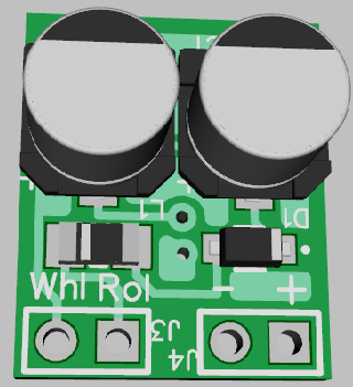
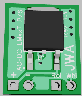


Thanks, but please keep watching. I think I have a long way to go yet, and I love getting all the help! ![]() I had a bit of background in wiring up electronic sensors and controllers, control panels, what did what, etc. Even learned how to release smoke! But, I knew nothing about the actual component level stuff or making PCBs until you guys got me interested here. I am still fascinated by all this and with today's modern design software, ease of ordering parts & PCBs, it really makes it all very possible even while not knowing a whole lot. That is with some good help of course.
I had a bit of background in wiring up electronic sensors and controllers, control panels, what did what, etc. Even learned how to release smoke! But, I knew nothing about the actual component level stuff or making PCBs until you guys got me interested here. I am still fascinated by all this and with today's modern design software, ease of ordering parts & PCBs, it really makes it all very possible even while not knowing a whole lot. That is with some good help of course. ![]()
It'll probably be a while before I get anything assembled, if ever. I need some more schooling in that department. And I still can't actually design anything without help from you and Stan. Plus you two have all the good ideas designed and built already.
Digikey parts are the only thing I have gotten with tariffs added. So far they haven't been a whole lot per part, just a few cents or so. But it could add up. If one can justify quantities you can make up for some of that added cost. As I am sure you know, Digikey has some pretty steep discounts when you get up to larger quantities.
I would use OSHPark if I ever come up with anything small enough. As a test with OSHPark, I just tried the PCB above, $35.00 for 3 PCBs. They really go up with larger sizes! The PCBs could be downsized somewhat, but not enough to make that big of a difference. I have tested with every PCB so far at OSHPark so far, and they were all pretty pricey.
I suppose learning about surface mount components should be coming up one of these days soon, Stan suggested that above, and I have been thinking about it. Then maybe I can really shrink things up some? I have only tried soldering one thing SMT, it wasn't pretty. Some practice in that department is on the learning schedule as well.
Not sure if this is of any interest, but you might consider if the led outputs can support additional loads. For example an application may want to drive logic for actual traffic control. I used a 3rd party traffic controller to drive a 4 way intersection using the MTH traffic lights. I added additional logic to control traffic. The vehicles start and stop on green and red. On yellow, it depends. If the vehicle is close to the light, the vehicle runs the light otherwise the vehicle stops. Actually, my vehicles are trolleys.
If I understand Stan correctly so far (emphasis on the 'if' and 'correctly' here), I don't think there is much extra headroom with the current version I am fiddling with using the CD4070 ICs. There is more load capacity with the 74xx86 ICs Stan first mentioned, but as he also pointed out those are only 5 volt. Seems to be a slight drawback to every plan, without adding a bunch of extra components. Again, as I am understanding this anyway.
However, I think Stan had the additional output loads in mond with the transistor and MOSFET versions above. Those are not CA - CC interchangeable by jumper selection, they would need separate PCBs for CA or CC. I am not sure of how much extra load they can handle, I'll have to look that up on the data sheets. (I don't know (or completely understand) all the components like Stan and GRJ do.)
Then there is the PIC chip that GRJ pointed out, which I also plan to start learning about and fiddling with. This would provide features more easily than using the ICs and also be easier to modify, possibly without adding too many extra components. But again I need to study the data sheet for this one, as the PIC chips are completely new to me. I have fiddled with an Arduino Uno, but there's a lot left to learn there as well.
I would certainly be interested in the 3rd party traffic controller you used, what all it does, and how it functions. Sounds very interesting to me. Did you completely replace the MTH controller with the 3rd party one or did you use them both together? Since this is really a learning project for me as much as anything, I would be interested in learning as much as I possibly can.
rtr12 posted:If I understand Stan correctly so far (emphasis on the 'if' and 'correctly' here), I don't think there is much extra headroom with the current version I am fiddling with using the CD4070 ICs. There is more load capacity with the 74xx86 ICs Stan first mentioned, but as he also pointed out those are only 5 volt. Seems to be a slight drawback to every plan, without adding a bunch of extra components. Again, as I am understanding this anyway.
However, I think Stan had the additional output loads in mond with the transistor and MOSFET versions above. Those are not CA - CC interchangeable by jumper selection, they would need separate PCBs for CA or CC. I am not sure of how much extra load they can handle, I'll have to look that up on the data sheets. (I don't know (or completely understand) all the components like Stan and GRJ do.)
Then there is the PIC chip that GRJ pointed out, which I also plan to start learning about and fiddling with. This would provide features more easily than using the ICs and also be easier to modify, possibly without adding too many extra components. But again I need to study the data sheet for this one, as the PIC chips are completely new to me. I have fiddled with an Arduino Uno, but there's a lot left to learn there as well.
I would certainly be interested in the 3rd party traffic controller you used, what all it does, and how it functions. Sounds very interesting to me. Did you completely replace the MTH controller with the 3rd party one or did you use them both together? Since this is really a learning project for me as much as anything, I would be interested in learning as much as I possibly can.
I didn't use the MTH controller at all. I used this one: http://www.galakelectronics.com/VG-303.htm. It's not expensive but it is working great for my application.
That is an interesting product indeed, thanks for the link. They also have some other interesting items and their prices are very good too. For $15.99 I couldn't resist your link above, one is already on the way! I'll have to figure up costs on a recent PCB and it's components, they might be selling theirs at close to what it costs me to make one here. Of course I never planned to sell anything, it's strictly a hobby and learning project, and quite enjoyable too.
I had planned to post the final results of all the projects here for others to use, but linking to this site might be a better option and much less work. I'll still post the results for those that like to tinker, but the linked board is really a deal, IMO. And I'll be revisiting their site for further study on some of the other items they have.
rtr12 posted:That is an interesting product indeed, thanks for the link. They also have some other interesting items and their prices are very good too. For $15.99 I couldn't resist your link above, one is already on the way! I'll have to figure up costs on a recent PCB and it's components, they might be selling theirs at close to what it costs me to make one here. Of course I never planned to sell anything, it's strictly a hobby and learning project, and quite enjoyable too.
I had planned to post the final results of all the projects here for others to use, but linking to this site might be a better option and much less work. I'll still post the results for those that like to tinker, but the linked board is really a deal, IMO. And I'll be revisiting their site for further study on some of the other items they have.
It's strange that the kit and assembled price are the same ? I purchased the assembled unit a number of years back and it was more than the kit. In any case my controller is working fine Good luck with your project.
I'm currently working on a cuing taxi loop. Taxi's (3) cue up in the rear of Grand Central Station and the lead cue taxi advances to the passenger pickup area in the front of Grand Central Station after the passenger pickup up taxi departs to the 59th street traffic circle. The 59th Street taxi returns to the rear of the taxi cue at the rear of Grand Central Station. The sequence repeats.
Access to this requires an OGR Forum Supporting Membership


