I was having trouble with getting uniterrupted power to one of my locomotives. After fiddling about with the rollers, and trying to weight the thing, I connected the other outside rail to the transformer and the affected engine now runs fine.


Was I remiss in not having both outside rails connected to ground in the first place? Is this simply "the way" it is done. If so, how come they sell these things with only a single ground clip? http://www.amazon.com/Atlas-60...oiners/dp/B0006N6MM6


Original Post

Replies sorted oldest to newest

The simple answer is no - you don't need to ground both outside rails using a wire.  A lot of people use an insulated outside rail to operate accessories, etc.


Atlas switches have a connection between the two outside rails.  This effectively grounds the outside rails if you are using Atlas track.  The uninsulated wheels of the cars also provide a ground path between the two outside rails.


I have not bothered to ground the outside rails on my home layout or on the G&O garden railroad.  Both layouts run fine.  You may have an unusual case where your home wiring grounding is not good etc of something else is going on.


Joe 

Most folks will probably say yes you should have them both connected to common. Some track like Fastrack and Lionel tubular already have the outer rails connected when manufactured.


I have done as Joe Barker stated above in his post and left one outside rail dis-connected for use as isolated rail controls for different items I want to add in the future. I am far from being an expert on this subject, but I have both Legacy and DCS (no conventional) and have not had any problems so far.


Thanks, guys. Thought I was perhaps doing it wrong at the get-go. This case is a new RDC from Sunset. I have two, just "out of the box" new. One ran flawlessly. The other stopped and stuttered and lurched drunkenly with lights a-flicker. Touching it and rocking

about a zillionth of an inch from side to side caused power to come and go.

Connecting the other outer rail to ground cleared it all up. Lima was right in that it was all coming down to one wheel on a four axle powered carand there was not enough weight on that wheel.

Terry,


Clean the wheels on the engine. Sometimes they are coated with manufacturing debris. I have had this happen on a couple of locos that drove me nuts. One was a RK steam engine.  It was not the pickup rollers ,it was dirty wheels.


Marty


Whether you call the outer rail ground or common is a question of semantics and context. It is understood in the context of universe of the track circuit,it is not earth ground. Old schematics of lots of things call a common return "ground". The definition in that context is a point of zero potential to the entire circuit. Pull a print of an old radio or TV circuit,or an automobile and you will see the common return referred to as ground. Not that this matters at all but I have rebuilt lots of amplifiers,etc. the metal chassis is referred to as ground,not common,and not to be confused with signal ground.


Here is a paragraph from a Wiki article explaining it


Electronics

Signal Ground.svg Chassis Ground.svg Earth Ground.svg
Signal
ground
 Chassis
ground
 Earth
ground
Ground symbols[7]

Signal grounds serve as return paths for signals and power (at extra low voltages, less than about 50 V) within equipment, and on the signal interconnections between equipment. Many electronic designs feature a single return that acts as a reference for all signals. Power and signal grounds often get connected, usually through the metal case of the equipment. Designers of printed circuit boards must take care in the layout of electronic systems so that high-power or rapidly-switching currents in one part of a system do not inject noise into low-level sensitive parts of a system due to some common impedance in the grounding traces of the layout.

Circuit ground versus earth

Voltage is a differential quantity. To measure the voltage of a single point, a reference point must be selected to measure against. This common reference point is called "ground" and considered to have zero voltage. This signal ground may not be connected to a power ground. A system where the system ground is not connected to another circuit or to earth (though there may still be AC coupling) is often referred to as a floating ground.


Dale H

Which track? Didn't Atlas have isolated rails at one time?

 Why would they only include one common pigtail? Well some companies don't include any. Is that total? Was this a "kit"? or per piece?

Per piece, simply alternate rails on a few. A pair seems skimpy on any pre-packaged package deal. But I wouldn't expect it on a piece order really.

 I say yes to two rail connection in general. I always connect to each rail with wires somewhere.  

The outside rails aren't linked on some brands, or in certain pieces of track.

This is left for the builder to do as many more wiring methods can use an isolation of the outside rails.

 Most jump connections like that have steel to steel plate, tabs, & rivets and the like, to carry the connection between rails.

  The movements of tubular kept them fresh. With metal so thin now and less movement, not the most reliable really. Connection numbers usually pull it off.

  Especially when built with todays minimalist production methods with little built in as far as overkill, Id run extra wire. On permanent layouts, drops every other piece to a bus isn't unheard of.  


 I'm not a fan of most "rail joiners" alone. Soldering a wire strand across the joint is what it took in other scales for solid rail to work best in a few brands.

    Id be doing tests for resistance, and voltage drops. Soldering small 3/8-1/2" wire jumpers at each rail joint gap is best outside of doing more pigtail drops. 

Small units, the RMT BEEP for instance, will have issues on a single outside rail being the common.  The single traction tire leaves only one wheel for the common connection, and any interruption and the locomotive stops.  I ended up using the non-traction wheelset from a BEEP frame (generously provided by Lee Willis) to eliminate the traction tire, problem solved.  I had similar issues with my K-line A5, I ended up adding a tether connection to the tender.

I bet although Dale definitely isn't wrong, to be right, I think a user should verify ground type by description at one point.

 I also feel ground is a term easily confused, and misused by those without a strong grasp of the nature of electrical circuits.

Especially in circuits that may contain both AC, and DC currents, using "common" when referring to AC track is my choice because "ground" is so often related to DC negative. But "return" would likely be a better word in the context I'm usually using.


 I usually skip over "correcting" it unless I see the terms user bouncing back and forth between the two terms and worry they may not really understand.

When folks don't pick one term per topic and stay there is . 


E.g.: I told an assistant once to give a dc board a new, heavier ground, and when I came back, he had tied to the ac earth ground  My fault.


A favorite teacher had a paraphrase she loved to throw around....


"A teacher of many, must assume the students know nothing each day"  

Originally Posted by stan2004:

All responses indicate connecting BOTH improves or at worst does not change performance. 


Ignoring isolated-outer-rail for accessory triggering, are there cases where a layout works "better" if you do NOT connect the outer-rails together?

In answer to your question, I can't see how it would work better by not connecting the outside rails together.

I agree with gunrunnerjohn relative to small units may have a problem if only one outside rail is connected to common.  My Thomas the Tank engine would lose power when trans versing one particular switch since only one outside rail was common. Fixed it by connecting the other outside rail to common.  You could see the engines wheels disconnect from the switch's one powered outside rail.

The outer lines connected to common will make a better connection; however when you want to use one or the other as a trigger isolate that section of track.


Otherwise why not use both rails as common until isolation is needed that way. I routinely do this on each Ross switch.( except where I want a non-derailing trigger.)

Last edited by AlanRail
Originally Posted by Adriatic:

Especially in circuits that may contain both AC, and DC currents, using "common" when referring to AC track is my choice because "ground" is so often related to DC negative. But "return" would likely be a better word in the context I'm usually using.


Definitely can be confusing terms. I enjoyed Dale H's links as I always do. However, I retired from the process piping industry and 'supply' and 'return' makes a lot of sense to me.


In my last 25 or so years, I worked with control systems and also with a lot of electricians. I always called the hot & neutral or hot & common 'supply' and 'return' when around them. The ones that knew me (and my sense of humor) were used to it, they would even do that to me (among other things). However, the newer ones would give me some very strange looks.


We enjoyed our work and occasionally even had some fun while doing it. I was fortunate to be able to work with a good bunch of folks for many years. Made the work a lot more tolerable some days.

Originally Posted by Adriatic:

I bet although Dale definitely isn't wrong, to be right, I think a user should verify ground type by description at one point.

 I also feel ground is a term easily confused, and misused by those without a strong grasp of the nature of electrical circuits.

Especially in circuits that may contain both AC, and DC currents, using "common" when referring to AC track is my choice because "ground" is so often related to DC negative. But "return" would likely be a better word in the context I'm usually using.


 I usually skip over "correcting" it unless I see the terms user bouncing back and forth between the two terms and worry they may not really understand.

When folks don't pick one term per topic and stay there is . 


E.g.: I told an assistant once to give a dc board a new, heavier ground, and when I came back, he had tied to the ac earth ground  My fault.


A favorite teacher had a paraphrase she loved to throw around....


"A teacher of many, must assume the students know nothing each day"  

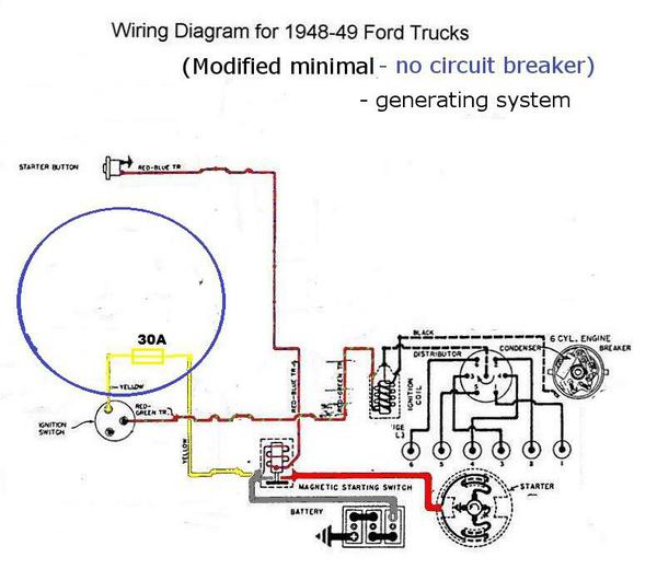
My 49 Ford had a positive ground and 6 volt battery. There was a grounding strap from the frame to the body as I remember and the battery terminal went to the frame. If you jumped it with a Chevy,you had to be careful not to touch bumpers. 


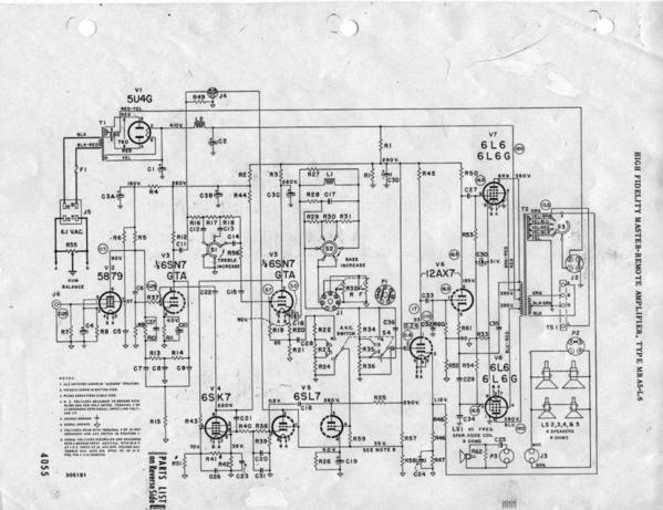
Here is a couple of diagrams drawn by some of those backwards Ford engineers at the time. Note the symbol for the "common return" as people like to call it.  Then it was referred to as ground. Earth ground had no meaning then,in the context of the car,which sat on rubber tires just like the cars of today today.  Which terminal is grounded is arbitrary. 


 Click to enlarge

1948-1949-ford-trucks-wiring-diagramTEMPcolorALT3


51-52wirediagram01


A typical Seeburg 1950s amplifier,the machine has a 2 prong plug. 


mra5-l6


 A closeup of grounds defined

a


Dale H

Attachments

Images (4)
  • 1948-1949-ford-trucks-wiring-diagramTEMPcolorALT3
  • 51-52wirediagram01
  • mra5-l6
  • a
Last edited by Dale H

I guess technically you should define your ground, but it has been common for 3 rail to call the outside rails ground.


QSI used ACG (I assumed the G stood for Ground) for outside rail and AC for Center rail.  Really only mattered if you wanted the Horn/Bell buttons to function correctly.


Lionel uses AC outer rail as the common ground for TMCC boards.


Once you get into DC circuit boards isolated from an AC "ground"  it does need to be identified.  You could easily have a + DC as the reference if you wanted.


Are we talking actual electron flow, or current convention?  G

Last edited by GGG

In my experience it makes sense to connect both outside rails to common.

It makes even more sense to solder all track connections to avoid a mechanical connection that could fail.


For example, connecting Atlas O track using a rail joiner, one might think that it would automatically connect the two sections electronically with just that mechanical connection. It guarantees nothing. Rail joiners may not make a good connection and they can fail. Solder.

I am with Scrapiron on this one...I can't tell you why I began to follow the common to both outside rails convention, but I do.


We are restoring a 12 year old layout that used MTH RealTrax. The layout was stored in an attic of a garage and recently in a non-climate controlled building. The track and some of the connector springs have crud build-up. MTH only connects one outside rail with the lock-on.


We jumpered the commons under the track where we soldered the track feeds. On the recently installed second level, the rails have not been cleaned. The test runs resulted in a sputtering pass and lots of sparks from the dirty track, but the engine made it around. Each run improved. The track cleaning will happen at the next work session.


So, connecting common to both outside rails can cover for several situations, such has engine axle configurations, bad rail joiners and serious crud. It still easy enough to create isolated rails for triggers.

Going way back to the start of O gauge, Lionel's tubular track had the the outside rails electrically tied together.  The track clip to connect power only connected the common to one of the outside rails.  It relied on the track itself to carry the ground to the other outside rail.   Most manufactures today still follow the practice of the basic track clip and supply the user with one hot and one common to go to the track.


With the advent of the more scale track and the use of wooden and plastic ties, the outside rails are no longer electrically tied together.  This leaves it up to the user to tie both outside rails to the common.  It is best practice to tie both outside rails to common.  This ensures the best electrical connectivity for the engine.  While larger, heavier locs will not see much of a difference, smaller, lighter engines will.

Last edited by Joe Fermani

My loops all have occupancy detection on the entire loop so one outer rail goes to a relay coil. The trains all run fine except for may be very small units with traction tires. Once the train occupies the block the 2 outer rails are connected anyway. If you are not doing block detection there is no reason not to connect them. However you are missing the opportunity to cheaply activate trackside accessories,block signal systems or make anti collision circuits easily  using inexpensive relays.


Here is one example of protecting a section using the outside insulated rail method and relays.


LINK


Dale H


Last edited by Dale H
Originally Posted by Joe Barker:

The simple answer is no - you don't need to ground both outside rails using a wire.  A lot of people use an insulated outside rail to operate accessories, etc.


Atlas switches have a connection between the two outside rails.  This effectively grounds the outside rails if you are using Atlas track.  The uninsulated wheels of the cars also provide a ground path between the two outside rails.


I have not bothered to ground the outside rails on my home layout or on the G&O garden railroad.  Both layouts run fine.  You may have an unusual case where your home wiring grounding is not good etc of something else is going on.


Joe 

This is the convention I following on the PRR Panhandle:

Inner Rail:  Common (Black)

Center Rail:  AC Hot (Red)

Outer Rail:  reserved for signal activation (insulated) (Green)


I run TMCC.  This has worked just fine.  I am careful to be consistent.  The same track keeps the same mission.  I don't switch tracks for the common.  By the way, I use GarGraves, Curtis, and Ross track with Curtis and Ross switches.


George

Last edited by G3750

I play around with the isolated rails too, but I use the outside rail for power as non of my isolated rails do anything truly important. I use the outside rail for power because the weight transfer in a curve gives better contact than the inside rail.

I don't think I ever did a count of traction tire units to know which side of the locomotives the most tires are mounted on. That could be another reason to decide which rail to use. 

We should call it potato.


Gents, I have seen 35V difference between "grounds" in separate sections of a building fed by different power poles. The whole "ground" thing is an illusion, its more like relativity. This is why wired Ethernet is differential signaling, and  has a transformer on the network interface section of the printed circuit board.


I wanted to move the ground clamp for the AC inlet panel down some on a copper water pipe so I could get a shut off valve installed to an outside faucet. I put a AC clampmeter around the connection before loosening it, and wow there was like 5A flowing thru it. So I took a set of jumper cables around the connection, making sure to press really hard on the copper water pipe to get a good connection. Actually I found an elbow and clamped on that.


To answer the OP's question, short answer, yes.

Last edited by illinoiscentral

My layout is currently wired with one outside rail for common and one for signal detection.  When I have perfectly clean track and reasonably clean engine wheels and pickup rollers, everything runs great.  But as soon as either the track or the engine wheels or rollers gets a little dirty, the gremlins begin to appear.  I am about ready to bite the bullet and connect the other outside rail to common and run the white flag up the pole.  I'm not ready to install signals yet and I'm tired of fighting it.


Art

Originally Posted by Chugman:

My layout is currently wired with one outside rail for common and one for signal detection.  When I have perfectly clean track and reasonably clean engine wheels and pickup rollers, everything runs great.  But as soon as either the track or the engine wheels or rollers gets a little dirty, the gremlins begin to appear.  I am about ready to bite the bullet and connect the other outside rail to common and run the white flag up the pole.  I'm not ready to install signals yet and I'm tired of fighting it.


Art

Art,


Are you running conventional, TMCC, Legacy, or DCS?


George

Originally Posted by Adriatic:

I play around with the isolated rails too, but I use the outside rail for power as non of my isolated rails do anything truly important. I use the outside rail for power because the weight transfer in a curve gives better contact than the inside rail.

I don't think I ever did a count of traction tire units to know which side of the locomotives the most tires are mounted on. That could be another reason to decide which rail to use. 

Other than one or two starter set steam engines, everything else has the rubber tires paired on an axle.

Originally Posted by G3750:
Originally Posted by Chugman:

My layout is currently wired with one outside rail for common and one for signal detection.  When I have perfectly clean track and reasonably clean engine wheels and pickup rollers, everything runs great.  But as soon as either the track or the engine wheels or rollers gets a little dirty, the gremlins begin to appear.  I am about ready to bite the bullet and connect the other outside rail to common and run the white flag up the pole.  I'm not ready to install signals yet and I'm tired of fighting it.


Art

Art,


Are you running conventional, TMCC, Legacy, or DCS?


George

George - I am running TMCC, Legacy, and DCS, but no conventional. 


Art

Add Reply

Post

OGR Publishing, Inc., 1310 Eastside Centre Ct, Suite 6, Mountain Home, AR 72653
800-980-OGRR (6477)
www.ogaugerr.com

×
×
×
×
Link copied to your clipboard.
×
×