A couple of questions for folks with more experience and wisdom


I am building a layout using post war equipment (i.e., without modern electronic control systems).  I have one very long loop that can easily accommodate 2 trains.  It passes a yard that includes a reversing loop so trains can go in either direction.  I plan on having four long blocks, with #2 acting as a control block for trains coming up too fast on block #1, and #4 doing the same for #3.  With relays, this is not that hard even with signals.  What is hard (to me) is figuring out how to make the system work with trains operating in the other direction (#3 controlling #4, and #1 controlling #2). Has anyone done this?  I have played around with a solution , but it looks way too complicated and expensive (4P2T switch, or a 4P3T switch if I include an override of the block power controls).


Second, i have read in the forum about having LED lights on a control panel to indicate which way turnouts are going.  I am planning to use SPDT switches with fixed power to control the turnouts, but if such switches are momentary on, won't the LED go off?  Or are there particular switches that allow the LED light(s) to stay on once they flip back to the center off position?  LEDs are a new technology for me since I built my last layout but very interesting.


Thanks again

Original Post

Replies sorted oldest to newest

A diagram might help. I am not sure what you are trying to do.  To determine train direction you can use 2 relays or a twin coil latch relay. Not what you asked but here is a sample circuit with direction logic


LINK


It might be better to let relays throw the switches and control the trains rather than have the switches control the trains. 


Here is automating a passing siding with relays


LINK2


Here is running 2 trains on one loop


LINK3


Dale H

Last edited by Dale H

Dale (and any other interested parties)


Took a look at your links and the rest of the site (cool stuff) and tried to apply the lessons to my problem.  Hope the attached is clear (my lousy artwork is up there with my electronics) - left out a lot of detail to focus on the logic.  I think it works but would love a second opinion.  


Many thanks

Attachments

Files (1)
Bi-Directional block control

Remember cab control wiring  using double pole center off toggles, You could assign a block to either handle  of our trusty KWs.. I'm  assuming relays can take the place of the toggles .

I spent months hooking up blocks with relays so I could sit back and watch'em go. The engines had to be locked in forward. Be careful,  what you wish for , watching them go became very boring  quickly. Fortunately I still had the toggles.


The fun part was trying to get it to work   however I could only figure out how in one direction.

 Here are the diagrams click to enlarge. What transformer is being used? I will digest them and get back to you


Diagram 1

long loop 2 ptr more trains running

Trains can run in either direction

Blocks A,B,C and D can be long


D1


Diagram 2

Assume relays are AC compatible with built in bridge

RB is self latching 3PDT

Blocks A and H effectively select IRA or IRB as control rail,can connect insulated rails in blow E,F and G as well


D2


 relay A is SPDT


Shows power off but will use resistors to hold in E unit


2 SPDT switches will be used to override block control

D3


Comment page


commnets


Dale H

Attachments

Images (4)
  • D1
  • D2
  • D3
  • commnets

 Before we get to the electronics, I have to understand how the loop works. I have a question on the first diagram as drawn. A train going counter clock wise can be reversed and made to go clock wise. However,a train going clockwise can not reversed and made to go counter clockwise,at least I don't see how. So please explain the loop to me and how it works.I don't see how the reverse loop would function. 


Dale H


Last edited by Dale H

Conventional--- No TMCC control or DCS


If NONE of your trains or equipment are modern,you don't need a TVS device,but you would still install external breakers as linked in my last post. . That is more to protect the wiring.


Breakers on your ZW should still work to protect the transformer itself. To test,short out A and U for example and see if the breaker trips. Also check cords for dry rot. If they are dry rotted replace them.


I can post diagrams when I draw them.They will be to protect the loop from collision and to boost or reduces voltage on the ramps. When trains go into the other section,top left ,you will have to make provisions for that if needed. I will try to circuit the loop from the entry points.


To do the loop as described you will need about 10, 25 amp bridge rectifiers,some optional 6 amp diodes (if you want automatic whistle blowing at a crossing),some 1 amp diodes (these are cheap,buy 50 or 100 of them),some capacitors,some barrier strips, some relays and appropriate wire. You will also need 1 or more ,twin coiled latch relays. These cost about $6 each. I will link the parts. To run the relays you will need most any starter set transformer as mentioned. You will have to do some soldering. 


Like I mentioned it is a bit involved but doable I think,at least I can draw it up on paper.


Here are links to the optional whistle blowing circuit. This is optional but the 6 paired diodes also act as a voltage dropper. 


LINK1


LINK2 


If you look at the board photo in LINK2, you will see the bridge rectifiers and 6 amp diodes used as a voltage dropper. If you construct one of these, you will have adjustable taps hooked to a barrier strip for easy connection and adjustment which will provide uphill voltage,flat surface voltage,down hill voltage and stall voltage. I think you said you wanted to leave voltage on for the E unit. If you lock it in forward you don't need so many bridge rectifiers. This is a little tricky but you can try it. You will not need wire wound resistors. The relays will switch voltage appropriately according to train direction in the loop. 


The concept of dropping voltage with diodes is explained here,I use it on my layout with success. See the third picture,you can construct one to slow your trains. 


LINK3


If you think you want to do this I will post diagrams and instructions ,step by step. 


Dale H

Last edited by Dale H

Dale


I have studied all three links --  can you help me understand the advantage of diodes versus resistors.  Have used the latter in the past but not diodes


Many thanks again.  I am game for putting just about anything together if I have a solid set of plans, so if I could see the diagrams I will give it a go!!


And thanks for your other thoughts today on circuit breakers, etc.


Jon

Diodes will drop voltage by a set amount,regardless of load. 


Resistors act in the circuit according to ohms law. Some engines,trains use more current than others and the resistors will distribute voltage accordingly. 


Under some circumstances a resistor can burn up if the track is shorted. In a short to the track you have a circuit through the resistor. Suppose we use an adjustable 5 ohm 25 watt resistor and adjust it to 2 ohms resistance. In a short at 16 volts throttle you have a circuit with 2 ohms resistance. That would allow 8 amps of current to flow through the resistor in the circuit. A ZW breaker would not trip since it trips at 10 amps or more. 16 volts at 8 amps would produce 128 watts of heat on a 25 watt resistor. You would have to fuse the resistor to protect it. Further a 25 watt resistor set at 2 ohms,40% of its value, becomes a 10 watt resistor. The bridge rectifiers are rated in amperes,25 amps and would be protected by the 10 amp breaker. The paired 6 amp diodes split the load with AC current and should do OK on 12 amps. 


However,the diodes do generate heat,just like resistors. They act like variable resistors in the circuit maintaining a steady voltage drop. The bigger the load the more heat wasted by the diodes (voltage drop times the amperage drawn through them).  It would be a good idea to convert passenger trains to LED lighting to reduce load,especially if running 2 trains on a loop. You also need to modify them to eliminate roller jumping. 2 rollers connected by a wire will jump center rails. This can be eliminated with 2 diodes or using 3 leads of a bridge rectifier in each lighted car. That is explained here. (last 2 photos 2nd link). For conventional I would use individual LEDs. I have several ways to do it in my posts at JCstudios.


LINK2


LINK


Anyway I will posts some circuits later that might help on the layout you are trying to do It is a bit complex.


Dale H

Last edited by Dale H

OK Jon


Remember this is all theory drawn on paper,click on diagrams to enlarge


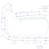
First,I divided your blocks and numbered them. There are 10 center rail blocks and 12 outside insulated rails. 1,2 is one block as a power block,but 2 outside insulated rails to detect train direction. The same is true for 11,12. Hopefully these can provide direction logic when the train enters from either side. This I will explain later. IR1 and IR12 need to be about 2 feet or longer. IR 2 and IR11 needs to be about 1.3 train lengths or longer. Blocks 3 through 10 need to be 1 train length or longer.


Jon 1


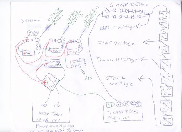
Next we add some electronic parts to try to accomplish out goal. On the right is a voltage dropper used to vary speeds on the grades and keep E unit active. If the train is locked in forward you don't need so many bridge rectifiers. On the left are the coil circuits to 4 relays,activated by the insulated rail method. The relays are powered by a starter set transformer. 18 volts AC makes 24 volts DC for all the relay coils to be used. Capacitors across coils in series with an 18 ohm half watt resistor reduce chatter and insure smooth operation. The small value resistor slows inrush a but to reduce sparking on train wheels.  Diodes across are for spike suppression.

Jon 2


The biggest challenge is to make a direction circuit which determines which way the train is going as it enters the block. If it enters from block 1 and 2 it is going clockwise. If it enters from 12 and 11 it is going counter clockwise. Hopefully we can trip a twin coiled latch relay reliably which will orient all the relays properly. The 4 relay contact sets will trip the latch relay right or left, depending on direction using capacitor discharge into the coils.


Jon 3


A train entering block 1 energizes relay 1. Relay 1 contacts charge capacitor 1 which also bleeds slowly through R1,1800 ohm half watt. (it is shown as 1000 ohms,we may have to fiddle with values). When the train proceeds to  block 2 and then vacates block 1, capacitor 1 discharges into the left latch relay coil A path of lesser resistance,about 700 ohms coil resistance),tripping the relay left in the clockwise position.


When the train leaves the section and enters block 11,the right latch will not throw because capacitor 2 is discharged through it's bleeding resistor 2. When it leaves block 12 and continues the capacitor discharges. The system works in a similar manner when a train enters from 12 and proceeds to 11. All this assumes the operator does not enter trains in opposite direction. So if a train is going clockwise in a loop we have the left coil latched. if the train enters counter clockwise we have the right coil latched. We will then use the contacts of the latch relay to energize another relay to give us multiple contacts to orient the relays.


JON 4


I shall continue this later as I draw up more schematics but perhaps you can see where this is going now. We will make a block system with 2 sets of relays,1 for clockwise and one for counter clockwise. The above will select which relays work according to train direction. It is critical to get the above working reliably.


Jon 5


Dale H

Attachments

Images (5)
  • Jon 1
  • Jon 2
  • Jon 3
  • JON 4
  • Jon 5
Last edited by Dale H

Dale


Wow - thanks very much for doing this.  I am about to leave for a week long business trip but will spend time studying this during my down time.  Based on my two readings so far I follow your logic, and see how this fits with some of the other links you have sent, but let me study it more.


thanks again,


jon

Originally Posted by NYC,SUBWAY TRANSIT SIGNAL:

WHAT IS IT TRYING ACCOMPLISH HERE ?  ITS LOOKS LIKE YOUR TRYING TO CONTROL THE SPEED OF THE TRAINS HERE. YES ?


Thanks, John kb2agpjohn@aol.com    OR ON MY CELL 848-992-2157

Hello John


Not exactly finished yet with the circuit. I still have to circuit collision avoidance as 2 trains can enter the loop. The block occupied will shut off the block 2 behind it. So if traveling clockwise, 5 will shut off 3, 6 will shut off 4 etc. Going counter clockwise 9 will shut off 11-12, ,8 will shut off 10 etc. To do that there will be 2 sets of relays,1 for clockwise and 1 for counter clockwise.   Look at Jon's early post. it explains what he wanted to do.


As for speed control,there will be a voltage for uphill,a voltage for downhill and a voltage for flat surface. There are 2 ramps on the section. This is made by voltage dropping diodes and  switched according to direction by the twin coiled mechanical latch relay. See my 2nd,3rd,and 4th diagram.


On my layout I use the rectifiers as a total throttle. Upon start the voltage is increased in 10 steps,the whistle and bell is activated automatically. It is accomplished by this board. The top relays do the bells, whistles. The middle section is the diode voltage dropper. There are 2 timers. One timer sets how long a train stops at a station or delay between one train on a loop starting after the last one arrives. The second timer controls acceleration rate. The bottom section are relays 4PDT that stage the voltage to the train. They latch up one at a time.When voltage is removed capacitors delay the relays closing which decelerates the train over about an 8 second period. For mandatory collision avoidance stops,this is much more abrupt,about 2 seconds.My layout scheme is less complicated than Jon's to do, as only 1 train runs at a time in the same direction but 2 or 3 on the same loop. I have one loop with a passing siding where trains run opposite.  With 5 loops running at once,this is a blessing if the trains have sound,it avoids competing sound systems. The trains actually run less,sometimes less is more. I run William, PS1 and Railsounds engines mostly,forward only.


whole board


As for Jons circuit,so far I have addressed only collision avoidance. More relays can be added to the latch relay to get more contacts. From this bi directional block signals can easily be circuited. Don't know if he wants to do that . 


Dale H

Attachments

Images (1)
  • whole board
Last edited by Dale H

Dalee


Have reviewed again and I think I follow the logic but a couple comments / questions


I do want to add auto signal light control


In terms of whistle control, is this to allow control from the transformer or separately?


I see the need for an override of the system for pure manual operation


I see the risk of the operator accidentally sending two trains from the opposite ends of the loop on a collision course but adding further complexity to the circuits to somehow prevent isn't worth it.   Assume the operator knows trains can only go one direction or the other, and the key focus is preventing one train from over taking another, especially if it is behind some mountain or wall.  If you want to take a crack at it, fine but I worry about spending a few months wiring this thing (but I am excited to try!!!)


Thanks again for your help !


I do want to add auto signal light control


(Fine,no problem just more relays)


In terms of whistle control, is this to allow control from the transformer or separately?


(Separately,either by operator pushing a button or automatically at a crossing.Automatic is explained in previous links)


I see the need for an override of the system for pure manual operation


(Simple,just a switch to the relay power to some or all of the relays. If all relays are off,all blocks have power)


I see the risk of the operator accidentally sending two trains from the opposite ends of the loop on a collision course but adding further complexity to the circuits to somehow prevent isn't worth it.   Assume the operator knows trains can only go one direction or the other, and the key focus is preventing one train from over taking another, especially if it is behind some mountain or wall.  If you want to take a crack at it, fine but I worry about spending a few months wiring this thing (but I am excited to try!!!)


(Opposite direction collision avoidance could possibly be done automatically,it depends on what is in the upper left separate section. Probably not needed. The block signals will indicate which way the section is going and indicate that to the operator. The block system will prevent 2 trains colliding in the same direction automatically. Again I am only addressing the section from the 2 entry points. I will later post a diagram the contacts on the 20 relays to prevent collision.)


BTW the first diagram is just an example of number of blocks. I drew 10 center blocks and 12 insulated outside rails, but this is arbitrary to give an example of how the system would work,hopefully. Your layout may have more or less blocks,depending on how it works out. The minimum lengths have been described previously.


If you have not purchased your GGs track,I would recommend you order it with 3 shiny tin plated rails rails. I think you can still order it this way from GGs. For what you are doing it would be best to solder block connections to the rail. You can solder to the black rail,but it is much easier to solder a wire to a tin plated rail.  Plan everything before laying track as far as insulated rails. They are harder to make when the track is laid. Run all wires to barrier strips for easy connections.  COLOR CODE YOUR WIRING,or you will go insane like me. If you go to an electrical section at Walmart or Lowes,you can buy rolls of colored tape. Wrap these around every so often as color tracers to identify wire. The cheapest wire to use is cut up extension cords,you can color code with the tape as mentioned. There are brown,white and green indoor, and 100 foot outdoor type. These are all 16 gauge wire. They can be doubled or tripled to make heavier gauges.2 #16s makes a #13 for example. A cheap ground buss can be made out of Romex house wire.   GGs offers plastic pins now, for between insulated sections,they didn't when I used their track long ago. I recommend them,they keep the track aligned.  I am using K-Line Shadow rail on the layout I am building. Will post later.


Dale H


To continue this saga from the last diagram posted,which shows block relay coils. The blocks are numbered as shown in the first diagram of the layout. Here is what one set of contacts will have do to shut off the train behind it. Click on either photo to enlarge


Jon 7


Here is a wiring diagram of one set of the relay contacts which does the above,I think it is right,you can double check it. The relays are DPDT,only one set of contacts on each relay is shown and used for collision avoidance to avoid confusion. The other set can be used for bi directional block signals which I will post later if interested.  Notice 4 relays and contact sets are not used. I included them because perhaps they can be used to shut off blocks in the upper left unprotected portion where the trains enter. As it stands blocks 1-2 and 3 clockwise and 11-12, 10 counter clockwise, are not protected from trains entering from the entry point behind it.


Jon 8


Dale H

Attachments

Images (2)
  • Jon 7
  • Jon 8
Last edited by Dale H

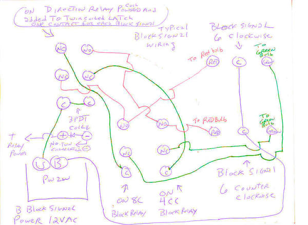
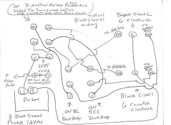
Here is the circuit for the typical installation of a 2 light block signals with light bulbs. 3PDT relays are added to the latch relay system as needed.  Up to 16 block signals could be used in the protected area,so that would be 6 relays. The approaches into the block as mentioned in the last post would have to be handled separately with the unused block relays. The wiring circuit example shown is for 2 block signals at block 6 one in each directions. 


Block signal 6 facing clockwise is red if the train direction is counter clockwise or if block 8 is occupied in the clockwise direction,otherwise it is green.


Block signal 6 facing the counter clockwise direction is red if the train direction is clockwise or block 4 is occupied if the train direction is going clockwise. Otherwise it is green.


LED block signals can be powered by adding a diode and resistor to each signal.


 Click on diagram to enlarge

Jon 9


Dale H

Attachments

Images (1)
  • Jon 9
Last edited by Dale H

Hi John,


I do that to a degree. Yours has more contrast,but you also took the colors off the wires. I use different colors so they are easier to trace for the beginner not used to diagrams,so my enhancement is a bit of a compromise between contrast and color. The user is free to download them also and adjust them. On a Mac just drag them on the screen and enhance them with Preview tools.  When I click and enlarge the photos they show up very readable on my 27 inch IMAC,my wife's 21 inch IMAC and also on the TV screen when I use my Mac mini. They do look washed out if you don't enlarge them.  I don't have a PC to view it on and am not familiar with Windows. 


What Jon has asked for is a bit complicated and needs lots of diagrams. It is actually easier to make up than explain how it all works. I still am not finished,I have to make up a circuit for the 2 entry block signals. The only thing I am not sure about is the capacitor discharge into the twin coiled latch relay. It should be able to accomplish with the right value components.  If that can be made to work,all else is pretty easy. 


Dale H

What program do you use to adjust the colors?  I bring down the overall brightness of scanned pages as the white fools the automatic adjustment.  Then, I bump up the saturation to 100% to bring out the colors.  This is the panel in PSP where all the adjustments are made.


You can fool with the control until you get the results you like.  I also sharpen the focus of most scanned images, that seems to help as well.  I think saturation is the key to getting the colors more vivid.


psp smart photo fix

Attachments

Images (1)
  • psp smart photo fix
Last edited by gunrunnerjohn

Here is the circuit for the entry clockwise block signal. A red signal would mean do not enter. A Green signal would mean entry is allowed and guarded electrically against collisions from the block system. The counter clockwise entry point at entry point 12 could be made in the same manner. With more relays you could shut off the loop or layout if the train ran entered when the signal was red.


 Click to enlarge


jon 11


Made as much contrast as I could with my Mac.


Jon 10


Dale H
Attachments

Images (3)
  • jon 11
  • jon 11
  • Jon 10
Last edited by Dale H

Add Reply

Post

OGR Publishing, Inc., 1310 Eastside Centre Ct, Suite 6, Mountain Home, AR 72653
800-980-OGRR (6477)
www.ogaugerr.com

×
×
×
×
Link copied to your clipboard.
×
×