


Interesting thought. What’s the nature of the DCS signal?
@cjack posted:Interesting thought. What’s the nature of the DCS signal?
The DCS signal is bi-directional, and the ability for the locomotive to talk back can't be amplified without internal control from the DCS controller, AKA the TIU. The DCS signal is also just present when there is a command coming and going, and it's mandatory to know what is happening in the command so you know when to turn the buffer off.
@Adrian! did quite a bit of research on this topic, and no practical solutions were forthcoming. If he can't get it working, I'm not going to even try! ![]()
TMCC/Legacy, OTOH, is a unidirectional signal that can be easily buffered because it's always there and it only goes out, there is no return traffic.
The TMCC buffer is simple in concept, any buffering of the DCS signal is anything but simple!
@cjack posted:Interesting thought. What’s the nature of the DCS signal?
Per John above .... Reposted for you:
Legacy is one way (base to train) signaling, so "buffering" is easy. The triangle (amplifier) points away from the base and towards the train.
The first issue is DCS is two way (train to TIU and TIU to train) signaling... so buffering is complicated since ... which way would the triangle point? If it just points one way it's not helpful since it will isolate in the other direction and you'll have no reverse signaling... and if you put two pointing both ways.... well then its just a loop of two triangles and now you have an oscillator. To do this successfully, you would need to "know" when a packet is about to go in one direction or another and switch in or out your triangle directions accordingly, which means the switching thing you build needs other logic signals from deep within the TIU (tapping the logic upstream of the output drivers)... to give your switch enough time to get the amplifier setup. Not easy with a big layout that has 20 or even more different TIU channels. You would need to tap all that logic on all the TIU channels in the layout to see when one of them somewhere is about to transmit a sequence.
The second part is the DCS packet timing: While we do know the sequence is always TIU-to-train before Train-to-TIU the TIU-to-train part is variable length (different commands --> different times) so it's not as simple as having an RC timer or something switch the triangle direction after a certain time constant so the amplifier points one way then the other. Unlike the TIU (who's firmware knows what command it is sending and what packet length it will be, and what response length to expect), you the outsider would need to extract this information from the outgoing packet to get these details for setting direction, and you would need to do it very very quickly since the packet you're decoding is also the packet you're steering the triangles for. That also means you're going to need some kind of fast look-up of the outgoing commands, too much for a microcontroller, it'd have to be an FPGA with a respectable clock... so now you're getting into the $1000 range.
The third issue is that we're talking about trains which move: Like mentioned above it's TIU-to-train, and train-to-TIU signaling. Understanding where to place the TIU-to-train amplifier is simple... you'd put it at the TIU before the connection to the layout... but how would you place the amplifier for the train-to-TIU signal? If you place it at the TIU, well the signals already gone through the layout at that point and all the ringing, distortion, and noise is already in there so an amplifier won't help much at that point. You'd need to place it inside the train (at the point where the transmission originates and is "clean")... That is you'd need to put modules in each locomotive one by one... with a $1000ish FPGA inside tapped into the PS2/3 board to get timing info.
The more you think about it ... the less sense it makes... and that's why we don't have such a booster.

Attachments
Images (1)

Interesting. So what’s like that? Cell phones?
Cell phones are full duplex, so they don't have the issues of determining where a data packet starts and ends. DCS is a single channel that can only handle traffic in one direction at a time, so there has to be a traffic cop to determine when it's OK to talk. As Adrain! says, the other major issue is a single DCS channel only services at most a couple hundred feet of track, so any logic has to be duplicated over and over. Finally, the engine return traffic being amplified is very costly.
@gunrunnerjohn posted:This is intended to be a continuation of the original thread for the TMCC signal booster to avoid confusion. I was working with Dale to create the "production" version of the buffer. That involved creating the PCB and building some units. Sadly, Dale passed away before we really got started, so without his input and documentation, the project languished for some time until recently. I enlisted the aid of another forum regular, PLCProf, to assist in recreating the schematic and getting to the point of confidence that we had a working design again.
Here's a recap of where I started after Dale's passing.
As some of you may know, I was working with Dale on this project, my end was to be creating the PCB and packaging once the design was proven. Due to Dale's untimely passing, the project was stalled. Since I never got to actually receive the final schematic, I did manage to round up the prototype. I enlisted some aid in reverse engineering and testing the prototype and the project is moving forward. We have reverse engineered the prototype and are making some tweaks. I'm hoping to maybe have a prototype PCB at York next month, however timing may be tight, so that's only about 50/50 right now. However, rest assured that it's coming soon.
I have what I believe is a completed schematic and I've done a board layout that should work with the enclosure I've selected. I haven't received the boxes yet, so there could be changes, one of the delays I mentioned. The "production" unit will have an off-the-shelf 24V power brick that is detachable. The terminal strip you see on the side will be the "Euro" style, but my 3D library didn't have those. Those terminals are where all the connections to the buffer are made. The board projection with the TO-220 package will have a heatsink mounted to the two large holes and also be outside the box, this is to allow air circulation for cooling the buffer chip. The white line on the board is where the enclosure wall will be, a slot allows the board projections. There is a power LED that projects through the top of the case, and also some signal level LED's that indicate a poor or missing base signal and also a "good" base signal. Connections are also provided that output a DC level corresponding to the signal strength of the input base signal and the output buffered signal.
Discussions should continue in this thread.
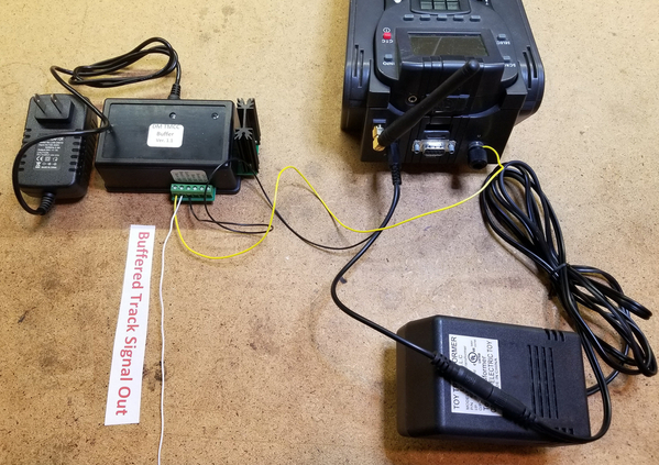
DM TMCC Buffer Connections To Command Base & Track
Are there any more of these available? and what is the cost if available.
Thanks,
Joe
John
I have one of your kits but our club is now interested in one. Are there any options now (ie. kits, or boards or gerbers and BOM)? I know this is late to the party . . .
Bob
Bob, send me an email and we'll see what we can do.
TMCC/Legacy Track Signal Booster as a diagnostic tool
First, let me say that I hate long forum posts. And I am now going to violate my own rule . . . So if you are short on time, skip down to the Cliff Notes at the bottom.
I finally got around to building my TMCC/Legacy Signal Booster kit. I have always had trouble with some TMCC Steam engines responding on my 15x25 home layout. This was somewhat unexpected although I have a lot of parallel tracks and tracks crossing over others. I just kind of muddled along with it.
Fast forward to York this Spring. Legacy just would not work on our modular layout in Purple Hall. I blamed it on the building wiring, and figured we were going to need to add a ground plane wire, or I could just build the Signal Booster kit.

The kit went together easily with GRJ’s excellent instructions and photos. So I was excited to hook it up to my home layout for a test. Power on. What?? The signal strength LED is red. With adjustment of the Signal Booster gain control it gets brighter, but it is still red. Have I had a bad Legacy base all along? At this point, as I am anticipating getting an RMA from Lionel, I decided to disconnect the Signal Booster from the track. Now I have a beautiful emerald green signal LED.
OK, now I have a layout problem. I pulled out the ohmeter and measured between the earth ground lead on the buffer and the outside rail. I got 7 Ohms. That’s not right! The layout is pretty much shorting out the Legacy signal. I am amazed that I had any control of my engines. (BTW, the Signal Booster worked so well, that by adding it, my engines responded flawlessly even with the signal mostly shorted out!)
Now started the hard work of finding the short. I do not have any ground plane wires. How is earth ground shorting to the outside rails?
I run Legacy and DCS. Track Power is from a Z4000, a Z1000 brick and a PH-180 brick feeding the TIU. My Legacy base is connected to an LCS WiFi module via the DB9 to PDI cable. The LCS wifi has a PDI cable connection to a Ser2 module which is daisy-chained to 6 ASC modules (TMCC) and 1 BPC module (not yet connected to track). The ASCs control Tortoise switch machines which are powered through diodes from the 14VAC Accessory terminals on the Z1000.
I re-connected the Signal Booster to the track (LED is red again) and one at a time starting with the Legacy base, I followed the problem down the daisy chain of connections:
Unplug DB9 cable from Legacy Base (green)
Unplug PDI from LCS to Ser2 (green)
Disconnect data wire to first ASC (still red)
Disconnect comm wire to first ASC (still red)
Disconnect A and U power connection to first ASC (green).
That’s it. The power leads from the 14VAC Accessory output on the Z1000 to the ASC relay contacts are shorting earth ground to the outside rail. To rectiify this, I moved the power leads to my Z4000 14VAC fixed accessory output and got a nice green light.
14VAC power leads circled in green:

I did verify that the ASC's U connection went to the Z1000 Common, and the ASC's A connection went to the Hot on the Z1000. I thought about reversing the connections, but the ASC manual specifically warns against doing this.
BTW, the Z1000 18VAC track output is phased with the other transformers (I did not check phasing with the 14VAC Accessory output). There must be some common connection in the Z1000 and/or the ASCs to cause this. I’ll leave that up to others to figure out, but at least I have a solution.
Here is a big Thank You to GRJ, not only for making the Signal Booster available to us, but also having the insight to add the signal strength LED feature. I would not have even thought of checking for a short from earth ground to my outside rail had it not been for the signal strength LED.
I’ll post Part II of this story in a few weeks when I use the Signal Booster on our modular layout at the York State Fair.
Bob
Cliff Notes:
1. The Signal Strength LED on the TMCC/Legacy Signal Booster is very useful.
2. If your TMCC/Legacy Signal is poor, check for continuity from earth ground to your outside rail. There shouldn't be any.
2. In my case, the power leads from the 14VAC Accessory output on the Z1000 to the ASC relay contacts are shorting earth ground to the outside rail.
Attachments
Images (3)
Tis interesting that you had a grounded situation and the signal generator wouldn’t respond correctly, so you had to clear the ground.
My problem was almost the opposite. I needed a ground and didn’t have it so I had a similar issue. My power adapter didn’t have a ground. A Lionel help call was no help at all and after I made the fix I told them about it and they said well, that’s good to know, goodbye.
Please read my posting of June 4th (Command Control Issue) and let me know if you believe it relates in any way to your problem.
I enjoy reading detailed explanations of electrical issues and yours was really good. Thanks
Well, we both had signal problems. Yours was due to the lack of ground plug in the Cab-1L power plug and therefore no connection to the house ground wiring. Mine was due to the ground wiring being connected to the outside rail. For a good signal, you need a good ground connection and a good rail connection and they must be isolated from each other.
Bob
Always like to hear success stories. When I started reading Bob's first post I was thinking there was an issue with the buffer, red with it should be green, green when it should be red. ![]()
John
As I was doing this troubleshooting, I started to wonder how feasible would it be to make a TMCC/Legacy signal strength indicator circuit using a subset of the TMCC/Legacy Signal Booster circuit? Obviously the comparator chip, LED, some passive components are needed. Maybe even a battery powered version?
Keeping your bi-line in mind, is this a project worth looking at?
Bob
Seems like there was a signal strength suggested by Dale thread years ago. Maybe a diode, etc?
@RRDOC posted:John
As I was doing this troubleshooting, I started to wonder how feasible would it be to make a TMCC/Legacy signal strength indicator circuit using a subset of the TMCC/Legacy Signal Booster circuit? Obviously the comparator chip, LED, some passive components are needed. Maybe even a battery powered version?
Keeping your bi-line in mind, is this a project worth looking at?
Bob
Actually, the NJ-HR club made a rolling TMCC signal strength detection engine. Turns out there is an output from the R2LC TMCC receiver that indicates the relative signal strength. They used a BlueTooth capable meter and carried the whole thing around the layout and could map the TMCC signal strength.
Graphing the TMCC/Legacy signal strength over an entire line
Thanks, I found it. Interesting., This link has the details about the meter/car.
Chuck, that's the thread I posted. ![]()
@gunrunnerjohn posted:Chuck, that's the thread I posted.
Oh sorry. I'm a bit flustered today. Sciatic nerve pain and that dumb k line engine.
@gunrunnerjohn posted:Most of the original thread disappeared, so anyone that expressed an interest should let me know.
I’m in John, well done.
Add Reply
Sign In To Reply
