
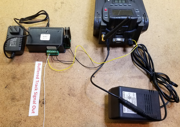
This is intended to be a continuation of the original thread for the TMCC signal booster to avoid confusion. I was working with Dale to create the "production" version of the buffer.  That involved creating the PCB and building some units.  Sadly, Dale passed away before we really got started, so without his input and documentation, the project languished for some time until recently.  I enlisted the aid of another forum regular, PLCProf, to assist in recreating the schematic and getting to the point of confidence that we had a working design again.

Here's a recap of where I started after Dale's passing.

As some of you may know, I was working with Dale on this project, my end was to be creating the PCB and packaging once the design was proven.  Due to Dale's untimely passing, the project was stalled.  Since I never got to actually receive the final schematic, I did manage to round up the prototype.  I enlisted some aid in reverse engineering and testing the prototype and the project is moving forward.  We have reverse engineered the prototype and are making some tweaks.  I'm hoping to maybe have a prototype PCB at York next month, however timing may be tight, so that's only about 50/50 right now.  However, rest assured that it's coming soon.

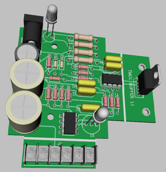
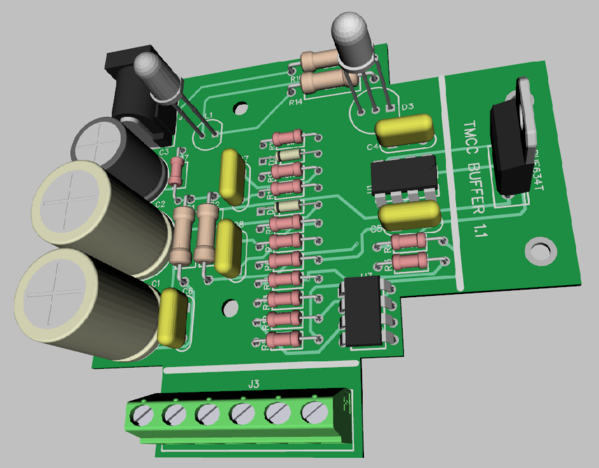
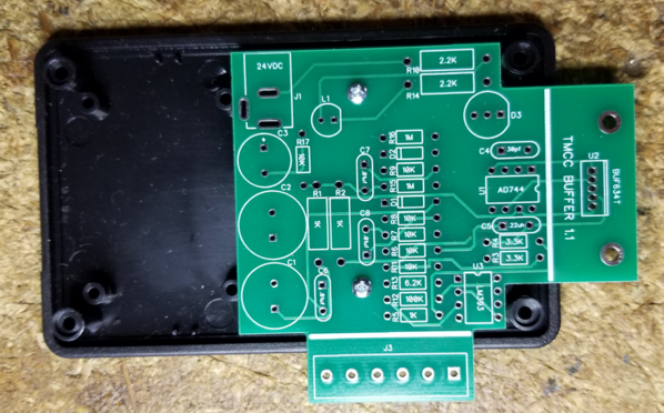
I have what I believe is a completed schematic and I've done a board layout that should work with the enclosure I've selected.  I haven't received the boxes yet, so there could be changes, one of the delays I mentioned.  The "production" unit will have an off-the-shelf 24V power brick that is detachable.  The terminal strip you see on the side will be the "Euro" style, but my 3D library didn't have those.  Those terminals are where all the connections to the buffer are made.  The board projection with the TO-220 package will have a heatsink mounted to the two large holes and also be outside the box, this is to allow air circulation for cooling the buffer chip.  The white line on the board is where the enclosure wall will be, a slot allows the board projections. There is a power LED that projects through the top of the case, and also some signal level LED's that indicate a poor or missing base signal and also a "good" base signal.  Connections are also provided that output a DC level corresponding to the signal strength of the input base signal and the output buffered signal.

Discussions should continue in this thread.

DM TMCC Buffer Connections To Command Base & Track

Attachments

Images (1)
  • mceclip0
Last edited by gunrunnerjohn
Original Post

Replies sorted oldest to newest

This track signal booster sounds good, I would be very interested in more information on how this works. Back in 2007 or 2008 Dale was at my home and we hooked up some sort of electrical apparatus on my layout, I think it was something to do with TMCC operation.  I have this unit on a shelf in my train room. Either way, Dale and I spent some quality time together as I gave him a tour of fine layouts in Tn., Ky., and Ohio.  He was a fine person, and very intelligent. Thank you Gunnrunner for continuing his work. 

John,

Thank you for picking up this topic!  Having not needed a booster in my small space with the TMCC controller I bought from you last year, I never responded as a Beta tester.  I did just buy a Legacy 990 a couple weeks ago, and got my first engine programmed without incident, so I just want to follow along.

"Dale's Legacy" sounds like a great name for the project!!  

leapinlarry posted:

This track signal booster sounds good, I would be very interested in more information on how this works. Back in 2007 or 2008 Dale was at my home and we hooked up some sort of electrical apparatus on my layout, I think it was something to do with TMCC operation. 

That was way before Dale worked on the TMCC buffer, so I don't know what that device was. 

The TMCC booster is designed to help large layouts that have a lot of capacitive coupling to earth ground.  That high capacitance kills the amplitude of the TMCC carrier signal and causes signal reception issues.  The buffer is a very low impedance 3:1 amplifier that can drive a lot more capacitance and still keep a reasonable signal amplitude.  I think Dale started on this one sometime in 2015.

Last edited by gunrunnerjohn

Thank you for responding, and I admit, I am not great at electronics. I am adding a picture of the Manco product I have. Maybe you can tell me what it's designed for. I was having signal issues around 2000 thru 2005 and Dale and I talked a lot. My situation was totally corrected with earth ground wiring. The new Legacy equipped engines run so great, no signal issues. Thanks fir this thread.IMG_8886

Attachments

Images (1)
  • IMG_8886
leapinlarry posted:

Thank you for responding, and I admit, I am not great at electronics. I am adding a picture of the Manco product I have. Maybe you can tell me what it's designed for. I was having signal issues around 2000 thru 2005 and Dale and I talked a lot. My situation was totally corrected with earth ground wiring. The new Legacy equipped engines run so great, no signal issues. Thanks fir this thread.IMG_8886

That is the booster for the output of the serial port (DB 9 connector on the Legacy Base) as it pertains to running multiple TPCs and some Z Stuff drivers. It has been "replaced" by Lionel with the SER2 module used with LCS and provides a higher power output from the serial port.

Thank you CJACK, I thought that might be what this particular accessory was intended for. However, when Dale and I installed it, for some reason it made little difference... I personally think the way my layout was wired up at that time was the problem.  The memory of Dale, and his 3 or 4 day visit, really was a learning experience, a fun adventure visiting my friends in the area, I will never forget. Dale told me his layout was in the attic, on the floor...This hobby is about the people in the hobby, that's why I enjoy this OGR Forum...Thank You.

Hi, guys this sounds great.  I have a issue with certain TMCC odessey F-3 PRR Green.  The A unit flicks in certain areas and will just stop the entire lashup.  It is the only engine I have doing it.  I have  about 900 feet of track.  If this is that type of issue please put me down for one as well.  Thanks guys y’all always have great imformation.


Bryan

John, 

As mentioned once before in the former thread, Bob De Guarde of the N.J.Hi-Railers had done a test with the buffer/booster on our layout for The Raritan Valley Hi-Railers, so Dale would have readings to analyze, a little over a year ago. We would like you to build us one for our group because at the Greenberg shows our layout usually runs 200 linear feet around. Our biggest issue is trying to get enough TMCC signal strength to the turntable/roundhouse area and would like to correct this so we can use the TMCC to move the engines instead of using the conventional mode. Thanks for all you do!

      Steam Forever

           John - Coordinator for The Raritan Valley Hi-Railers

                      Member: N.J. Hi-Railers

For anyone with an email in their profile that replies, I'll send an announcement out when we're ready to proceed, probably in about a month or six weeks from now, sometime after York.  After the testing of the prototype, we'll move on to making them.


Churu posted:

Please John don't forget about me, of course I would like to get one

Note that you don't have a profile email.

George, the booster will be in a small plastic enclosure about 4" x 2.5" x 1.5" tall.  The buffer output amp heatsink will project out one end, and the six terminals for system connection will project out the side.  The back side will have the plug for the 24V power brick.  The top will have the two indicator LED's.  This is the board that's inside the case, the heavy white lines denote where the board projects through the case.

There is no mounting provisions, however my advice is some sticky-back Velcro strips to attach it to the location of your choice.  If you want to be able to see the power and signal level LED's, the top should be visible.  Three of the terminal connections are required, earth ground, base input, and track output.  The other three are provided for measurement of the input base and output track signal relative levels.  They output a DC voltage that can be measured with any 1 meg-ohm or higher impedance meter (most digital meters).  The earth ground will be tapped off the TMCC or Legacy power brick plug barrel with a male/female adapter that has a wire to attach to the buffer earth ground terminal.

I'd post a picture of the actual unit, but I don't have the prototype board in yet, I expect to have it before York, at least that's my plan.

Attachments

Images (1)
  • mceclip0

How large would a layout need to be to need one of these? If I ever get to my expansion plan I will have about 16' x 22' L shape with a yard of about 6' x 16' added on somewhere if I can fit it in. I have only a 6' x 16' layout now and everything works well. Just thinking about getting one just in case. It's also gonna have 2 levels if I ever get to it. 

Last edited by rtr12
G3750 posted:

Thanks John!  I will check this out at York.  Where will you be?

I'll be around.  I'll be at the Henning's Trains booth some of the time, but I have to try to spend some money as well.


rtr12 posted:

How large would a layout need to be to need one of these? If I ever get to my expansion plan I will have about 16' x 22' L shape with a yard of about 6' x 16' added on somewhere if I can fit it in. I have only a 6' x 16' layout now and everything works well. Just thinking about getting one just in case. It's also gonna have 2 levels if I ever get to it. 

It's not really how large, it's whether you have the specific issue that this will correct.  You'll probably have to build the layout to find out if you have an issue.  I've seen layouts considerably larger that had no issues with TMCC.  Folks like the NJ-HR or Elliot (Big_Boy_4005) here in the forum have layouts the size that will likely benefit from this buffer.

Once the production run is over, there may be a nice market for any extras.  I'm planning on this being basically a one-time build, like Lionel's BTO process.  

What I'll probably do is make the PCB files and the BOM available if someone feels the need to have one after the initial run is complete.  Given the need to buy all the stuff like the enclosures, etc. in bulk to insure having them, I can't really afford to be stuck with a bunch of extra units.

This seems to be going the way of giving meaning to the saying, let no good deed go unpunished.  I wonder how many guys want one and don't know why.  I'll bet a fair share don't even have a layout.  You're hot right now.  Enjoy your newfound celebrity.   Or at least make a couple bucks off it for the effort.  Nice work and best of luck with the project.

That sounds like a plan to me. I can see where you wouldn't want too many left over, but I would imagine there might be some more folks interested when the train season gets going again here pretty soon? You never know though?  BTO sounds like the best idea. That's quite a bit of assembly too, as it looks like there is a good number of items ordered already, with more still coming in! 

Thanks for all the effort you are putting into this too! I appreciate it as I am sure the others do too! And thanks to PLCProf also for helping.

William 1 posted:

This seems to be going the way of giving meaning to the saying, let no good deed go unpunished.  I wonder how many guys want one and don't know why.  I'll bet a fair share don't even have a layout.  You're hot right now.  Enjoy your newfound celebrity.   Or at least make a couple bucks off it for the effort.  Nice work and best of luck with the project.

 I'm not quite sure what point you're trying to make.  I don't think this will be a big moneymaker, but I figured this was a good thing that should be at least offered.  Besides, I like the idea that I can give a little money to the American Cancer Society in Dale's memory, he certainly gave us a lot. Also, it's been interesting to solve some of the issues associated with producing it.  I'd be remiss in not mentioning PLCProf and his invaluable contributions to the reverse engineering process.  Since we didn't get anything but the prototype due to Dale's untimely passing, we had to do it the hard way.

I'm going to make sure the documentation is around after the project so in the future it can be produced again if desired.

Last edited by gunrunnerjohn
gunrunnerjohn posted:
 
rtr12 posted:

How large would a layout need to be to need one of these? If I ever get to my expansion plan I will have about 16' x 22' L shape with a yard of about 6' x 16' added on somewhere if I can fit it in. I have only a 6' x 16' layout now and everything works well. Just thinking about getting one just in case. It's also gonna have 2 levels if I ever get to it. 

It's not really how large, it's whether you have the specific issue that this will correct.  You'll probably have to build the layout to find out if you have an issue.  I've seen layouts considerably larger that had no issues with TMCC.  Folks like the NJ-HR or Elliot (Big_Boy_4005) here in the forum have layouts the size that will likely benefit from this buffer.

In my case, I have over 3000' of track spread out over 1900 square feet. I'm guessing a bit here, but I would say that if you have less than 1000', your layout probably shouldn't need one.

That said, there could be track configuration issues which might make the booster necessary. I agree with John, build the layout first. If everything works, great. If not, try some of the other well documented fixes first. If you are still having trouble, it would be a good idea to build the signal strength test car, and map the layout with it, then go for the booster.

For the record, even the booster has not solved all of my problems. I still have a number of engines that don't like certain spots, but the booster has made it possible to run most of the engines over the entire layout.

Would there be an advantage using this on a layout that's currently working okay so that it'll already be installed for future layout expansion or can too strong a tmcc signal be harmful having a detrimental, adverse effect causing problems and issues on a layout, sort of like "anything done to excess or too much of a good thing can be bad for you"?

Last edited by ogaugeguy
gunrunnerjohn posted:

Don, if you look back, you'll see that what is going to happen is I'm going to send out a group email to all that expressed interest and give them a chance to make a firm commitment.  That will allow me to order the proper amount of parts and not have a pile of expensive and unused parts.

John, knowing how at times some forumites have posted they would buy things and then when it's available - they don't follow through, since you aren't yet certain of what the cost will be, might I suggest you require a partial, nonrefundable, upfront deposit when they commit to buying one, sort of like a pre-order. Otherwise, you might possibly find yourself with a sizable amount of "I want one"s which go unclaimed and unbought.

ogaugeguy posted:
gunrunnerjohn posted:

Don, if you look back, you'll see that what is going to happen is I'm going to send out a group email to all that expressed interest and give them a chance to make a firm commitment.  That will allow me to order the proper amount of parts and not have a pile of expensive and unused parts.

John, knowing how at times some forumites have posted they would buy things and then when it's available - they don't follow through, since you aren't yet certain of what the cost will be, might I suggest you require a partial, nonrefundable, upfront deposit when they commit to buying one, sort of like a pre-order. Otherwise, you might possibly find yourself with a sizable amount of "I want one"s which go unclaimed and unbought.

That's part of the plan.  Since the parts cost for this unit is over $50 before any work goes into it, that's probably in the ballpark of what that deposit will be.  After the run is finished, the design files will be available for anyone that wants to fabricate one themselves.

ogaugeguy posted:

Would there be an advantage using this on a layout that's currently working okay so that it'll already be installed for future layout expansion or can too strong a tmcc signal be harmful having a detrimental, adverse effect causing problems and issues on a layout, sort of like "anything done to excess or too much of a good thing can be bad for you"?

 I don't see any advantage to installing one on a properly working layout.  I don't know that it would do any harm, but I don't have any actual data to back up that belief.  My feeling is you install this box is a last resort after you've run grounding wires and insured your track and connections are in good shape.  The major issue this solves is for large layouts with lots of track, there is excessive capacitive coupling to earth ground, that causes the amplitude of the TMCC signal to be too low for reliable operation.  The box is a low impedance buffer that is capable of driving high capacitance loads without losing amplitude.  It also provides some amplification of the signal voltage.

Last edited by gunrunnerjohn
gunrunnerjohn posted:
ogaugeguy posted:
gunrunnerjohn posted:

Don, if you look back, you'll see that what is going to happen is I'm going to send out a group email to all that expressed interest and give them a chance to make a firm commitment.  That will allow me to order the proper amount of parts and not have a pile of expensive and unused parts.

John, knowing how at times some forumites have posted they would buy things and then when it's available - they don't follow through, since you aren't yet certain of what the cost will be, might I suggest you require a partial, nonrefundable, upfront deposit when they commit to buying one, sort of like a pre-order. Otherwise, you might possibly find yourself with a sizable amount of "I want one"s which go unclaimed and unbought.

That's part of the plan.  Since the parts cost for this unit is over $50 before any work goes into it, that's probably in the ballpark of what that deposit will be.  After the run is finished, the design files will be available for anyone that wants to fabricate one themselves.

ogaugeguy posted:

Would there be an advantage using this on a layout that's currently working okay so that it'll already be installed for future layout expansion or can too strong a tmcc signal be harmful having a detrimental, adverse effect causing problems and issues on a layout, sort of like "anything done to excess or too much of a good thing can be bad for you"?

 I don't see any advantage to installing one on a properly working layout.  I don't know that it would do any harm, but I don't have any actual data to back up that belief.  My feeling is you install this box is a last resort after you've run grounding wires and insured your track and connections are in good shape.  The major issue this solves is for large layouts with lots of track, there is excessive capacitive coupling to earth ground, that causes the amplitude of the TMCC signal to be too low for reliable operation.  The box is a low impedance buffer that is capable of driving high capacitance loads without losing amplitude.  It also provides some amplification of the signal voltage.

Any gain control in the design? 

I'm in for the deposit, just say the word when you get further along.

No gain control, the buffer is a fixed 3:1 gain.  That's where all the testing has been, and trying to make sure nothing bad happens at all gains on all layouts would be a lot of testing.  Dale did a lot of work on the design and tested it in a number of locations.  Unless someone comes up with a good reason to change it, I'm sticking with his basic design.  We added some monitoring and tweaks, but the basic design is all Dale.

There's always version 2 if there's a reason, but I think just getting the signal there is the key requirement.

micp125 posted:

John, 

Please put me in for one. Likely the Club will opt for one as well.!

Thanks for your dilligence.

I would, but there's no email in your profile.

leapinlarry posted:

Would this booster help with adding Lionel's wifi operating system? My layout us 36 by 17 and is a winding 5 level layout...all Legacy Command...Thank You 

The WiFi and the booster are totally different areas of operation, it shouldn't help or harm the WiFi operation.  It's strictly to improve the TMCC/Legacy track signal.

We're slowly marching on.  This looks to be the "final" board configuration.  As soon as I get prototypes and do a full and final test of the design, I'll be ready to proceed.  This also represents the proper style terminal block that will be used for connections.  Note that the terminal block is now represented as the correct Euro style that I'll actually be using.

TMCC Signal Booster 3D 2017-09-30

Attachments

Images (1)
  • TMCC Signal Booster 3D 2017-09-30
micp125 posted:

"xxx@yyy.net". I found that there are 2 places in our profiles where ones email need be listed. Thanks again. See ya next week.

Doug

Doug,

While some folks have no problem putting their email in an open forum, I'd recommend you keep the email address in your profile where it is only available to other forum members.  I might be over doing it on limiting my personal data; due to the recent hacking of several domains probably all the bad guys have all my data anyway.

No need for money yet Ron, the big expensive order will come after I have deposits for the cost of the parts.  Right now it's mostly sitting on my hands waiting for the prototype PCB's to come in, then I'll have to wait again for the final spin of the PCB to come from China.  Since the parts are all from local distribution, I'll order them once all the long lead items are in hand.

Unless OSH Park falls on their ear, I should have a working prototype at York.

gunrunnerjohn posted:

No need for money yet Ron, the big expensive order will come after I have deposits for the cost of the parts.  Right now it's mostly sitting on my hands waiting for the prototype PCB's to come in, then I'll have to wait again for the final spin of the PCB to come from China.  Since the parts are all from local distribution, I'll order them once all the long lead items are in hand.

Unless OSH Park falls on their ear, I should have a working prototype at York.

John:

Looking forward to seeing it at York.  Please keep us informed of the status.

Thanks,

Bill 

Hello John,

We were out on vacation when I found your post on this booster, I replied to the post from my phone but as I looked through all these replies I did not find mine. I don't know if my reply may have gone to Dales original thread which is closed or if it just went out to hyperspace, but, I would like to have you add me to the list of folks wanting to purchase one of these signal boosters for my S gauge layout.

Ray

gunrunnerjohn posted:

Hmm... Shipping to Canada, what's that, about $100?

Sounds about right!  Add another 1/2 by the time Canadian Border Services get their hands on it.

I can coordinate the shipping so that it can be bundled in with my next order from Henning's.  No hurry on this end so whenever it's convenient.

Thanks John

Bruce

Last edited by brwebster

TMCC BUFFER PROGRESS REPORT

The prototype has been assembled, and the bench testing went well, looks like it works just like Dale's original.  A 5V p-p signal in from my BASE1L yields a 15V p-p low-impedance signal out from the 3:1 power buffer driving a 50 ohm load.  Testing with various capacitive loads is ongoing, but it's looking good.  Extended running under load didn't cause any issues, the buffer appears to be loafing doing it's job.


Prototype TMCC Buffer on the bench.  The blue LED is power, the green bi-color LED is indicating good signal strength.  For a truly weak or no signal, the LED will be red.  For a low amplitude signal, but still probably usable, the LED will be extinguished.  I find that most old TMCC bases don't have the signal drive to light the LED, but the three Legacy bases and the BASE1L that I tested all had sufficient amplitude to light the green signal LED.  You can also measure a DC voltage that is proportional to the amplitude of the input and output signals on the measurement terminals.  In the final documentation I'll have a table that correlates the DC voltage to the p-p voltage of the signals so you can evaluate the signal levels without a 'scope.


Prototype TMCC Buffer in enclosure, The power and signal strength LED's project through the top.  There is no signal applied, and as you can see, the signal LED is red in this shot. 

Right away I spotted one issue, I put the LED's too close to the edge of the board and they don't come through in the recessed section of the top.  I also had to trim the board a bit as it was about 1.5mm too large for the enclosure.  I didn't actually have the enclosure in hand when I did the board layout, and my guess of clearances was just a bit off.


Armed with the mechanical knowledge gained by assembling the first prototype, I did a re-spin of the board to fix all the things I saw wring with the first layout.  I optimized the buffer circuit section component layout, and sized the board properly for the enclosure.  I also moved the LED's so they'll be correctly positioned on the flat part of the enclosure.  The holes in the middle of the board mount the board on the bottom plate of the case.  Hopefully, this is the "final" layout.

We are sailing along!

Attachments

Images (4)
  • mceclip0
  • mceclip1
  • mceclip2
  • mceclip3

FYI, here's the complete "package" that will be included with the buffer.  Obviously, the buffer box itself, then there's the 24V power supply, and the earth ground tap cable.  That cable goes between the TMCC or Legacy base power brick and the base itself.  The single wire is connected to the barrel of the base power supply which is the earth ground (3rd prong of the outlet).  This is connected, obviously, to the earth ground terminal of the TMCC buffer.

Yes, there will be nicer looking labels, but I didn't have them yet, so I just taped on the connection data and the name.

TMCC Buffer Complete Package

Attachments

Images (1)
  • TMCC Buffer Complete Package

I'm targeting probably about a month to six weeks for firm commitments.  At that point, anyone that wants one will put down a deposit to cover the cost parts as I don't want a lot of expensive parts around that I don't use.  The deposit will be on the order of $50.  At that point, I'll make the final parts order for the quantity that I have deposits on.  When they're assembled and tested, all the folks with deposits will be notified and make shipping arrangements.  Right now, the final price looks to be $129 including the $20 donation for each unit going to the ACS in Dale's memory.  That gets you everything you need to install it, the buffer, the 24V power brick, and the earth ground cable to tap off the earth ground from the TMCC/Legacy power cord.

TMCC Buffer Complete Package

 Given the realities of ordering printed circuit boards in quantity, I'll probably have blank boards after the initial build, it doesn't really cost much more to order 100 vs 50, around $10.  At that point, my plan is to make the design available for anyone to assemble that missed out on the initial build.  Since I'll likely have blank boards, those will be available on a first come, first served basis until they're gone.  Obviously, certain parts will be more expensive in quantity one, and things like the enclosure I'm using may no longer be available, that's the downside of waiting until later. 

Attachments

Images (1)
  • TMCC Buffer Complete Package
Last edited by gunrunnerjohn

Hello John.

I vacillated back and forth as my new layout under construction could be considered "large". It is multi-tier and passes thru (2) enclosed drywall areas but without scenery or anything else to block a signal...I do have a earth ground wire but notice some areas (especially in the rooms)  that may be an issue.

Bottom line, if it is not too late....please add my name to the list for (1) unit.

I would rather be prepared now than regret my decision later.

Thank you for providing this service to us all.

Donald

Last edited by 3rail

Yep, as I said before, once all the testing is complete and I have 100% confidence in the final design, I'll contact everyone that expressed interest in the buffer.  By the time I get back from York, I hope to have samples of the "final" board, so I'll be assembling a couple of those for the testing to insure all is well and we didn't screw something up in the process.

gunrunnerjohn posted:
Big_Boy_4005 posted:

John, is it possible to ask permission from his family? Using the original name would be a great tribute.

I guess it's possible, but I'm not sure who I'd ask.  I'd hate to get bogged down in something as simple as a name and have that consume more time that the project.

I hear ya. Case of sleeping dogs as it were.

How about Dale's TMCC/Legacy signal booster by: (you fill in the blank as to how you want to take your credit).

FWIW, I like the naming idea using Dale in there somewhere. I wouldn't think something like AlanRail suggested DM Booster or similar would cause any problems. It would be like an 'In Memory Of' type name. However, naming it Manco or something like that using what Dale used for his products could cause a problem I would think. He may have that name as his company or trademarked or however one IDs their products. 

IMODM... In Memory of Dale Manquen maybe or just back to the DM Booster... ??? I don't see how naming something in memory of would cause a problem? But I am no legal authority either.

Just some food for thought. And I think it's a good thought about Dale too.

Kerrigan posted:

Cleaning up some old files I found a diagram for a "TMCC SIGNAL BOOSTER" .... from a long time ago.  Wonder if it was one of Dale's early diagrams ... did someone else come up with a booster design?  I'll have to go to the pile and see if it has a date on it ...

I remember a tube design posted on the forum...I’m not remembering who’s it was.

Last edited by cjack

Finding tubes for my old 1930's radios is bad enough, my stepdad dealt with them while working as an instrument tech for A Nuclear facility, he did well, 30 years they have worked better than some old transistor radios we found in moving and actually fit the décor heading into my train room.

Are you sure this is Dale's design?  I agree with PLCPROF, what prompted him to do with 1950's parts?   With the LED pilot light, I really wonder about the 6X4 rectifier, surely the solid state replacement was more than available by then!

Thanks for posting it, it was 99% curiosity, I don't know what happened to the stuff I had about this.  I maintain my position, I'm going to stick with the solid state version!   I'm not sure the two tubes would even fit in my current enclosure, and I'm almost sure they'd melt it!   I know that 5" piece of 1" PVC would NOT fit into my enclosure!   That transformer is no piker either, it's a chunk of metal!

You can read Dale's own words on why he used the tubes for his initial design.

"I started out designing a solid state amp, but quite frankly I got lazy.  I thought that Jim's circuit would allow me to determine just what problems I need to address."

Dale had a design from Jim Lefevre which he used as an initial starting point.

He did replace the 6X4 tube with solid state. The 6X4 was Jim's design.

Dale's goal was to use the vacuum tube design, do some testing and then design the solid state version.

You can read Dale's design thoughts in the attached PDF.

Glenn

Attachments

On Dale's website he talks about the Vacuum Tube design

http://www.trainfacts.com/trainfacts/?p=486

"UPDATE 5/8/13

I have built a booster amplifier based upon the vacuum tube design of Jim Lefevre, adding a few embellishments of my own.  I hope to test the amp on some large layouts in the near future."

Dale posted the Vacuum Tube schematic on the OGR forum in May 2013.

Glenn

PLCProf posted:

I'd love to see the tube version, either the schematic or the real thing. You could probably build one with nothing but the parts from an old AA5, for you radio guys out there.

Just morbid curiosity. 

Here are some pics. I grabbed these off the forum when the topic was running a few years ago. Rich was not pleased to have this info on the forum, citing potential FCC violations arising from the unit. I saved all the particulars, in he event that it would get deleted. It got locked, but I believe it is still out there somewhere.

I believe the name you guys seek is Jim LeFevre. If I'm not mistaken, these are his photos. The date was 10/2/14.

IMG_3728IMG_3729IMG_3730IMG_3731

Of course, after working directly with Dale to help test his electronic version, It rendered the tube version moot.

Attachments

Images (4)
  • IMG_3728
  • IMG_3729
  • IMG_3730
  • IMG_3731

Dale brought his booster to Scottsdale not long before he passed, it was one of his final trips and I am glad I met him. It vastly improved our layout and we were bummed when we had to ship it to the NJ HR.

We are ecstatic that you are finishing his design John. I will be depositing money with you for 3 units at York. 

Ron

PennsyTurbine posted:

You can read Dale's own words on why he used the tubes for his initial design.

"I started out designing a solid state amp, but quite frankly I got lazy.  I thought that Jim's circuit would allow me to determine just what problems I need to address."

Dale had a design from Jim Lefevre which he used as an initial starting point.

He did replace the 6X4 tube with solid state. The 6X4 was Jim's design.

Dale's goal was to use the vacuum tube design, do some testing and then design the solid state version.

You can read Dale's design thoughts in the attached PDF.

Glenn

Thank you for the insightful comments. I had some questions, and you had the answers!

How about “THE BIG BOOST”,  a TMCC Signal performance  enhancer brought to you by, Gunnrunner John, designed by the late Dale Manquen, Another Manco product for the serious Lionel  TMCC/Legacy Operator.  I would think the product name should state what it does.  It does enhance signal performance. Yes, I want one to. Thanks for your hard work. Leapin Larry 

gunrunnerjohn posted:

Are you sure this is Dale's design?  I agree with PLCPROF, what prompted him to do with 1950's parts?   With the LED pilot light, I really wonder about the 6X4 rectifier, surely the solid state replacement was more than available by then!

Thanks for posting it, it was 99% curiosity, I don't know what happened to the stuff I had about this.  I maintain my position, I'm going to stick with the solid state version!   I'm not sure the two tubes would even fit in my current enclosure, and I'm almost sure they'd melt it!   I know that 5" piece of 1" PVC would NOT fit into my enclosure!   That transformer is no piker either, it's a chunk of metal!

Those docs were put up by me.  Dale Didn't design it.  Jim Lefebrve (spelling?) did.  I found the plans on Google Groups and put the parts list together when we built it.  It works great and makes a world of difference on our layout but will be retired in favor of John (and Dales's) solid state buffer.    It cost about 3 x John's unit to put together and we'e gone through a couple of tubes to boot.     I put pics of it up further in this thread and the pics in the post a few above this are of our unit.

Last edited by Chris Lord

I'm sure hoping that the "new" TMCC booster doesn't go through any parts as it works!   However, the credits should read Dale Manquen, PLCProf, and John, all were instrumental in bringing the project to this state.

I thought I remembered someone else designed it and Dale was doing some experimenting and mods, thanks for publishing those original design pictures.

Around the time Dale passed away someone (here I think) posted some links to things he had been involved with over the years. It was pretty impressive!! He was in audio, tape recording I believe it was so maybe the reason for liking 'tubes' over solid state? Anyway I read some of the info and it was pretty amazing. Some of the things he had done were impressive and he was well respected in the field. 

Sorry, I don't remember the post or poster. However, if you do a google search on 'Dale Manquen' a lot of info comes up about his work in tape recording and audio, if anyone is interested. Most was over my head, but still interesting to read, IMO. I might be the only one here that did not know about this, but if not I thought some of you might want to do the search and see what all Dale had worked on during his career. Anyway, if anyone is interested try the search, I think it's well worth the time to read some of the articles.

Also not to stray from the topic of this thread, so no further comments please. Just thought others might be interested as I was and wanted to share this with anyone that, like me, did not know about Dale's work. 

Big_Boy_4005 posted:
PLCProf posted:

I'd love to see the tube version, either the schematic or the real thing. You could probably build one with nothing but the parts from an old AA5, for you radio guys out there.

Just morbid curiosity. 

Here are some pics. I grabbed these off the forum when the topic was running a few years ago. Rich was not pleased to have this info on the forum, citing potential FCC violations arising from the unit. I saved all the particulars, in he event that it would get deleted. It got locked, but I believe it is still out there somewhere.

I believe the name you guys seek is Jim LeFevre. If I'm not mistaken, these are his photos. The date was 10/2/14.

IMG_3728IMG_3729IMG_3730IMG_3731

Of course, after working directly with Dale to help test his electronic version, It rendered the tube version moot.

Yes, the PVC tube is part of the drawing.  Did it work?  Looking forward to the DM version.

Done guys. 

I also got the latest PCB in, after York I'll assemble up a "production" unit and see if I missed anything in the layout.  I have discovered it's a bit more difficult to get something that fits precisely into an enclosure with projections than just making a PCB.

Looks good, I have to mod the case and see if everything works.

Attachments

Images (1)
  • mceclip0
Last edited by gunrunnerjohn
bigdodgetrain posted:

my club has informed me they would like two of these.  you should have my email from past correspondence with you.  if not let me know.

Please send me an email on this.  I normally just take the profile address, but you don't have one.

BTW Roger, you don't have a profile address either.

Last edited by gunrunnerjohn

Just finished building what I hope is the "production" model.  The completed unit consists of three pieces.  Obviously, the actual buffer unit itself, a 24V 1A power brick, and an "earth ground" tap for the command base.  The ground is tapped off the outside of the power barrel, this is the connection through the command base power brick to the 3rd wire on the plug.  Connecting the buffer is dirt simple.

  • Connect the earth ground tap between the command base power and the brick
  • Connect the loose wire on the ground tap to the Earth GND terminal on the TMCC Buffer.
  • Connect the track signal output wire from the command base to the Base INP terminal on the TMCC Buffer.
  • Connect the Boost OUT terminal of the TMCC Buffer to the layout track connection.

The buffer is ready to go.  Plug in the 24V power brick, power up the command base, and start running trains.

The three other connections to the buffer box are for DC meter measurements.  You can read a relative level of both the BASE DC signal and the BOOST DC output signal referenced to the GND DC pin.  These will possibly be useful in the future when we want to compare results between different layouts to evaluate the effects of capacitive loading on the buffer output.  Note that these are optional outputs, they don't ever have to be used to effectively use the TMCC buffer.  The circuitry that drives these also drives a signal level LED, red is very low or no base signal, off is marginal base signal, and green is a good base signal.  I usage note, if there is nothing connected to the Base INP terminal, you may see the signal level indicated as green (good).  This happens because stray AC is being fed to the buffer from the floating input, it only happens if there is no connection to the input.

This unit is going out for a real layout test, it'll be tested on the NJ-HR layout.  Upon satisfactory test results there, I'll be ready to order parts for these.  Stay tuned...

DM TMCC Buffer N1DM TMCC Buffer N2

Attachments

Images (2)
  • DM TMCC Buffer N1
  • DM TMCC Buffer N2
rad400 posted:

John

I received the buffer today and plan to do  preliminary  testing on Friday and then use it on Sunday for our club's open house.

Bob D.

I will probably get a lot of crap for this but here goes anyway.

the MTH experts at our club are worried that this signal booster will de-grade the MTH signal.  What I would like to ask is can you take pictures of the mth remote showing signal strength without the booster in place and again with the booster installed?


thanks

gunrunnerjohn posted:

We're taking our time with the move, it'll be over several months.  That's the benefit of moving 4 miles.

When I moved around 20yrs ago the moving company came to give me an estimate, when he asked me where I was moving to I pointed to the house two doors away. At first he thought I was kidding, then he said really,  I'll never forget the look on his face.

Art 

bigdodgetrain posted:
rad400 posted:

John

I received the buffer today and plan to do  preliminary  testing on Friday and then use it on Sunday for our club's open house.

Bob D.

I will probably get a lot of crap for this but here goes anyway.

the MTH experts at our club are worried that this signal booster will de-grade the MTH signal.  What I would like to ask is can you take pictures of the mth remote showing signal strength without the booster in place and again with the booster installed?


thanks

If I have the time next week I will take the measurements.

Bob D

As some one who has been involved in various aspects of RF engineering (amateur radio,  broadcast engineering and systems design)  for the past 56 years, I doubt that there will an interference issue. TMCC operates at 455kHz and the DCS operates between about 3.3mHz and 10mHz.  There is a significant frequency separation between the systems. Once a booster is available (two on order), I will be able to give an absolute response as I have both DCS and TMCC available on the layout that I am currently constructing.

John,

I am a member of the " Paradise and Pacific " model railroad club in Scottsdale, Az.  I was present @ the layout the day Dale stopped by to demonstrate the TMCC/legacy signal booster.  I must say we were ALL very impressed with his devise. Of course we were very sad to hear of his passing. . . . . . .

PLEASE add me to the list to purchase this legacy signal booster.

I am a brand " NEW " OGR  forum member, and mag subscriber. . . .

John B.

John,

That's correct our club has two maybe three preordered. Some of our members may have placed orders too?

After experiencing this devise first hand. I knew I wanted one. The results were amazing. Besides It's the squirrel in me that wants to stash it away. . . . .Just in case ! I'm so new to this forum, and format, Can you see my email address John ? So you can let me know when they're ready ?

Thanks for your response,

John B.

ogaugeguy posted:
gunrunnerjohn posted:

... this is one of those devices that 98% of TMCC/Legacy layouts probably don't need, it's only large layouts and perhaps exacerbated in multi-layer layouts.

John, do you anticipate having one on your new layout? I ask that because it seems your layout will be mid-size but not humongous .

I don't anticipate needing this for my layout.

Just a small update as to the status of the project.  The testing went reasonably well at NJ-HR, but Bob did have a couple questions that we're still chasing down.

I would like to find one other site to do some testing, obviously it should be one that has significant issues with TMCC without the buffer.


There has also been a delay due to the fact that I'm in the middle of a somewhat messy move in the dead of winter.  Being in limbo for a spell is putting a crimp on many of my train-related activities as there are lots of things to do here.

Add Reply

Post

OGR Publishing, Inc., 1310 Eastside Centre Ct, Suite 6, Mountain Home, AR 72653
800-980-OGRR (6477)
www.ogaugerr.com

×
×
×
×
Link copied to your clipboard.
×
×