Sorry to get into this again, but I am still fighting with an SC-2 which stops working after an hour or so of powered up time.
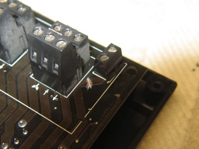
I have a new one arriving tomorrow. I plan to do some internal testing with freeze spray to try to find failing component before swapping in new unit. One of my questions is where the SC-2 gets power to operate its relays. In a 6 switch setup, there is no wall wart power and I understand that using the power in terminals in this configuration is not workable. Since the only wires connected to the SC-2 are the same three which would be connected to the lighted switch controllers which came with the switches, and those three are center common and the thru and out connections, where does the SC-2 get the power to run its relays and internal electronics?