I have a volt/ohm meter but when tracing an electrical problem several months ago I found, with help from folks on this forum, that a lighted car enabled me to pinpoint where a power feed drop connection had failed. So I’m wondering what other techniques/tools are needed to diagnose electrical problems?


Obviously, what is prompting this question is that a problem has cropped up. I’m using conventional cab control for my layout (about 300' of track), eight insulated blocks with SPDT toggles for each block switching between the left or right handles of a PW ZW. (I use a second KW transformer for switches & accessories.)I also recently wired in two diode ladders into the circuit for whistle/bell control. I’m detecting significant difference in train speed as well as passenger car illumination between the two handles of the ZW and my suspicion is pointing towards the diode ladder. The ladder for the right handle has 5 diodes pairs per side and the one for the left handle has 6. (I used Dale H's & Gun Runner John's circuit & instructions). It’s such a difference that a 6-car passenger train slows down to a crawl when controlled by the left handle yet when I switch to the right handle, it speeds right through and the car illumination brightens.


So I have two questions:

  1. Could the one diode pair difference in the two whistle/bell controllers account for such a speed difference when the same train is controlled by the different sides of the ZW or should I be looking for a different culprit?
  2. My volt/ohm meter does not show any significant difference in voltage when toggling between the left and right handles. It’s not a very expensive meter costing less than $7 (analog) so I’m wondering, do I need either a better meter or some other tool to diagnose this problem and what other tools or equipment do I need for trouble-shooting in general, either now or in the future?
Last edited by Former Member
Original Post

Replies sorted oldest to newest

Last night I swapped the hot wires coming from the A & D posts of the ZW to the diode strings and the problem reversed! Now the train is creeping along with the handle on the right and fine with the handle on the left.


Now what?? If the diode string with the 6 pairs is causing the problem, how do I determine it it's one bad diode or do I simply remove the pair at the far right and see if that resolves the problem in that both diode strings will be in balance?

Well, the mystery deepens. I'm not sure what you meant about shorting out each diode. Did you mean run a small piece of wire across the two leads of each one individually?


I did do a continuity test of each diode and they're all good! I tested both directions also, making sure that there was no current flow - to + for each one individually as well as flow + to -.


I'm at a loss other than to eliminate the sixth pair of diodes so that both sides of the transformer match and see if that accomplishes anything. The only other thing I can think of is maybe there is a problem with the left side of the ZW. I could tap the "A" post of the KW and swap it with the D post of the ZW.


Any other suggestions would be appreciated.


I'm just grasping at straws. The ZW is 60 years old plus or minus 5 years, and has never had any service on it. (Hasn't needed it, actually). Thinking about it, I did meter the A/U & D/U posts recently and they're both putting out 18 - 20 volts.


I'm am suspicious of the diode string with the six pairs. Can you briefly describe which of the two leads of each diode pair do I connect together? Also, wouldn't the continuity test I performed on each individual diode reveal which one was bad?

I don't know what test you actually performed, or exactly how it was performed, so I can't say if the test was valid.


My original suggestion was to simply move the diode strings between the two locations.  If you did that, you eliminated the transformer and the tracks, you stated that the issue followed the diodes.


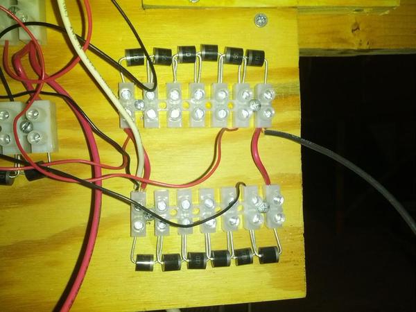
How about a picture of exactly what you have for the diode strings that seem to be the problem?

When I get home from work tonight I’ll take a picture and post it. And yes I did swap the hot wire from each transformer post (A & D) and the problem moved to the opposite side.


In performing the continuity check, I touched the leads from the meter (set to Ω) to both leads of each of the individual diodes.  In one direction I would see current then when I swapped the leads from the meter there would be zero current. I did this on all 12 diodes.

Here is my Whistle/Bell controller. The white wire is coming in from the D post of the transformer, the black wire goes out to an old fashioned cab control matrix of 8 barrier strips & toggle switches, that flip control of a particular block from the left handle to the right handle. The smaller wires go to the terminals of a DPDT toggle to activate either the whistle or the bell.


Oh, and I should mention that yes, the horn or whistle & bell work fine.

IMG_20140319_181326

Attachments

Images (1)
  • DIY Whistle/Bell Controller: DIY Whistle/Bell Controller - D Post of ZW
Last edited by Former Member

What I'm saying is illustrated in the following picture.  Just work your way down the diode strings in the same manner, shorting one diode pair from the string for each test.  See if any single shorted diode pair fixes it.


My guess is maybe one of the diodes is not handling the current, even though it might look OK with a meter test.


diode

Attachments

Images (1)
  • diode

I just wanted to finally report back on this. It's been a few weeks but my wife and I decided we couldn’t take the winter anymore (even though it was Spring) and flew to Turks & Caicos for some warmth.


Anyway, upon returning, I tested each pair of diodes as discussed previously and could detect absolutely no difference in train operation regardless of which pair I shorted out. As a last resort I completely removed one pair of diodes from the six-pair group that is connected to the “D” handle of the ZW, turning the six-pair controller into a five-pair (same as the “A” handle)and voila’, problem solved.


It’s hard to understand how one additional pair of diodes could make that much of a difference in the amount of voltage going to the track. I did meter it and it looked like no more than a 2 volt difference but regardless, it was just enough to stall a 2-motor post-war engine w/4 passenger cars (GG-1 Congressional Set). Strangely, with a more modern engine, a WBB U33C (so I could test the bell & horn) in place of the GG-1, the problem while still evident, was not as severe.

Post

OGR Publishing, Inc., 1310 Eastside Centre Ct, Suite 6, Mountain Home, AR 72653
800-980-OGRR (6477)
www.ogaugerr.com

×
×
×
×
Link copied to your clipboard.
×
×