
Doing a search I found several references to whistle controller construction but the actual pictures and components would not show up. Does anyone have a link to this or have pictures of procedures and componets to construct a whistle controller to blow modern whistles and bells through my post war transformers. I know a series of diodes and switches is what’s needed but need diagram , specs and any instructions. I am sure it has been described on this forum but if the post is old some pictures have been lost or deleted. someone might can direct me without going to the trouble of reposting.

thanks

dogdoc


Original Post

Replies sorted oldest to newest

I first saw the above diagram on the JCS O gauge archive site; the site seems to come and go but was working today anyway.  There are some additional comments, but no photos.

Someone named gunrunnerjohn posted the following photo in this earlier OGR thread.  Not the exact circuit as in above diagram, but I think a reasonable facsimile of what would be involved with the string of diodes and switch method.

mceclip2


Attachments

Images (1)
  • mceclip2

Stan, that's probably where it came from.  I'm pretty sure it was from Dale H. who used to frequent the forum, but I haven't seen him n quite a while.  I do recognize that other whistle control, I couldn't find the pictures on my computer, I was going to post that one.

I'm glad to hear the J&C Archive is back up, I figured it was gone for good when it was missing for several months.

Gunrunner John 

excuse my ignorance as I am weak on tracing current flow. In the box you made for bell/whistle can you trace the current flow when each switch Is opened. It looks like to me that when the switch on the left is open, current would only flow through one diode assuming the current follows the path of least resistance ? Or would it also flow through the lower array of diodes? I just received the components to construct your controller 
thanks

Dogdoc

The current in one direction goes through all the diodes, in the opposite direction it goes through the one diode and the switch.  That imparts the DC offset to the track and triggers the whistle/bell function.

Note that for normal running with no switches depressed, the current goes through all the diodes in each direction.  That results in an insertion loss of around 3-3.5 volts, so typically it takes a bit more throttle to move them out.  OTOH, for many conventional locomotives with can motors, the lower starting voltage actually helps low speed running.

@dogdoc posted:

...So current follows 2 paths when the first switch is open? Not just the one through the single diode?

I believe when you say a switch is "open" that you mean it is pressed "on" and thereby electrically shorting its two terminals?   I get the analogy that an "open" door lets air flow in and a "closed" door blocks air flow.  But in the electrical world, an "open" switch means current is NOT flowing.  Perhaps just semantics; in any case see if this helps:

diode controller

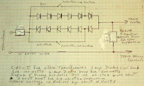
In all 3 cases (normal, whistle, bell) current flows in BOTH directions.  When the incoming voltage is positive (RED), current flows thru the lower path of diode(s).  When the incoming voltage is negative (BLUE), current flows thru the upper path of diode(s).

As GRJ says, in addition to understanding where the currrent is flowing, the key to the operation of this type of controller is that a diode reduces the voltage as it passes the current.  It's kind of like a 3/4 Volt tax.  Pressing one or the other button essentially bypasses 4 of the diodes leaving just 1 diode in that direction.  The other direction still has 5 diodes.  So this offsets the average voltage, and of course this offset voltage is what the engine detects to trigger its whistle/bell.

As mentioned in an earlier post, one artifact of using this method is in normal operation (neither button pressed), the 10 diodes (5 in each direction) are nevertheless imposing the voltage tax and there is reduced AC voltage to the engine.  A valid criticism of this method is that those diodes are burning power in normal operation; modern controllers use different techniques so as not to waste power.  But considering the simplicity and cost of this method, it's a reasonable tradeoff all things considered.


Attachments

Images (1)
  • diode controller

Hi all, just stumbled upon this thread today.  I was just wondering last night if there was a way to control the Whistle/Bell downstream of the transformer.  For my future layout, I'm planning on using conventional control with transformers divided up between various loops and blocks.  Certain transformers would be used for the bigger/multiple loops where less individual train control would be needed at all times.  I was wondering if there was a way to individually control the sounds of the train per block/loop as opposed to only at the transformer.

One question, should the push buttons be also rated at 6A?

I may try building a little "sound control" box as a test and see what happens.  Thanks!

Truthfully, running conventional mode, you only have one engine in the picture on a particular power district, so 6A is more than enough.  Since I just built mine for the workbench, I use junkbox parts, that was 3A diodes.  Also, keep in mind that the diodes are only passing current in one direction, so truthfully the pairs diodes would be within their ratings with 6 amps of current in the circuit.

For your application, you'd run the power to each block through the box and then on the the track.  That way each box would only affect that power district.

Add Reply

Post

OGR Publishing, Inc., 1310 Eastside Centre Ct, Suite 6, Mountain Home, AR 72653
800-980-OGRR (6477)
www.ogaugerr.com

×
×
×
×
Link copied to your clipboard.
×
×