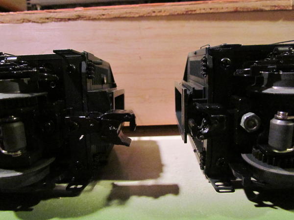
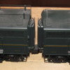
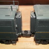
I recently purchased a set of Lionel A-B-A New York Central Sharks. Great set of locomotives.They pull,look and sound real good,except i wish the gap between the units was closer.Does anyone have any tips or advice on how to close that gap.Thanks
Replies sorted oldest to newest
I have both MTH and Weaver Sharks, and they run very well. They have the same problem that you are experiencing with the Lionel. I do not understand why any of the aforementioned brands do not make diaphragms for these locomotives. I have searched for an after market source and have come up empty. Perhaps someone out there can help Mr-150 and myself.
Weaver has diaphragms, search their web site.
I closed the gap on my AA RF16s. I first fitted a K line 1 .25 " dummy coupler to the np unit. This was fairly easy, the coupler had to be ground down and the screw hole enlarged. K line passenger diaphragms for their streamliners fit the door frame on the sharknose well, after cutting a section of the inner ring of the diaphragm to go around the handrail in the door frame. The inside ring on the diaphragm fit between the door and door frame. Lastly a piece of black thin foam-core was fit to go inside the diaphragm such to hold the inner ring against the door frame. All of this is reversible so you can readily restore the engine to as built condition, very important to me. So far it looks good and runs well, although the modification may limit the engine to larger radius track than it could navigate prior to this. Parts and shipping cost less than $10 Fred
Can you take another picture with a white 3x5 card behind it?
audi, thanks for the tip on the dummy coupler and diaphragm. What are the K-line part numbers for those parts and who would i be able to get those K-line parts from Mark
Lionel also makes short dummy couplers as well as 1.44" electro couplers used on the Trackmobiles.
I used truck mounted kadees to close the gap on some Lionel F3s.
Before:

After:

Pete
audi, thanks for the tip on the dummy coupler and diaphragm. What are the K-line part numbers for those parts and who would i be able to get those K-line parts from Mark
Mark, The parts are from Brasseur's, K Line. 2100-11-1r 1- 3/16" dummy coupler, K 4400 13-1 diaphragm. Here is a pic of the set. Fred
Attachments
audi, thanks for the tip. I just placed my order with Brasseurs Mark
I am interested in the B&O sharknose but that gap is a deal breaker for me. So I email Mike Reagan to see if they do make short couplers to use on the A unit and B unit of the sharknose. As usual quick to respond. He said "but the shoulder height, hole diameter may not match up to what you need from the stock dummy couplers on the sharks. If you want to monkey with it, you are of course more than welcome. " So I guess the question, how difficult is to modify their coupler to work in this case and has anyone done it? BTW, on my layout I have no curves smaller than O72.
Thanks
I thought about shortening the 'tween units spacing on mine (B&O) but they look good in spite of it and I can run them on tighter radius looks if I want, so I kept them as is for now.
You could probably use the 630-4678-055.
Bill
Hi guys
Eric sigel of Erics trains converted his using KD couplers, I quite like them as they are. Do you guys think it would look OK to put bellows between the A-B-A units?
Ernie
Here is the link on how I did mines as per the Lionel part number from boxcar bill.
https://ogrforum.ogaugerr.com/t...64#36484918293812964
Here is the link on how I did mines as per the Lionel part number from boxcar bill.
https://ogrforum.ogaugerr.com/t...64#36484918293812964
The short shank coupler is no longer available at lionel. Hope they restock because I need some more.
Can anyone tell me what the turning radius becomes on the Sharks if I were to switch out the standard couplers for the shortened Lionel couplers or Kadee couplers similar to those used by Eric S. in his review on youtube?
Hi All,
A little late to the party, but I was in the same boat as everyone else with the gap issue on my Lionel B&O sharks. As David1 previously posted, the short Lionel dummy coupler #630-4678-055(Centipede dummy coupler) is still unavailable from Lionel as of 2 weeks ago. After digging around the Lionel parts area on their website, I came up with a few couplers that worked for me. Lionel dummy coupler #630-9610-055(listed for use on E-9's) is a drop in replacement for the stock long dummy couplers on the rear of both A units and both ends of the B units whether they are powered or non powered. These shorter dummy couplers measure approx. 1.400" long compared to the stock dummy couplers length of approx. 1.750" long. While not as short as the Centipede dummy couplers, the E-9 dummy couplers, when mounted on both engine units, reduce the distance between the units by approx. 11/16"-3/4", which is quite a bit. In the pictures below, I have 2 B units, one powered, one non powered, coupled together and sitting on MTH 042 Realtrax. There is approx. 1/16" clearance between the door sills of the units. Note that I replaced the electrocouplers on the B units with the dummy couplers, as I will be running the engines as a multiple unit set(See, I didn't use the lashup word!!!). I was a little surprised at the price of these dummy couplers at $6.50 each, but after receiving and inspecting
them, they appear to be made from brass!!!
For those who wish to keep their electrocouplers on the B units, there is also a shorter version of that also, Lionel part #620-8447-550. This electrocoupler has an approx. length of 1.440" compared to an approx. length of 1.744" for the stock electrocoupler, which would shorten the distance on that side by approx. .300". However, this shorter electrocoupler is not quite a drop in. There needs to be approx. 1/32" or so of metal removed from either the outer radius of the coupler mounting pad on the truck or from the face of the coupler that butts against the coil windings on the bottom side. This is to let the coupler move forward enough for its mounting hole to drop down over the mounting post on the truck. If it were me, I'd remove the metal from the radius on the mounting pad, as trying to remove the metal from the coupler will put you VERY CLOSE to the wrapped coil windings. Anyway here are a few photos and I hope this may help someone else close the gap on their sharks.
Nick
Attachments
Nick, can you show a photo of the reduced gap with the engines on straight track?
Thanks,
Doug
Just as an aside, and I don't do much diesel fiddling, I have used, on one set of AA locos,
a draw bar in place of both couplers (shades of the original EMD FT). A brass (typically)
piece cut to appropriate length and drilled (drill more than 2 holes, to adjust/experiment),
and using the coupler mounting screws on each truck. More difficult if the locos have
"fancy" couplers on the "B" end. But doable and mountable.
Not for all situations, but for those where it makes sense it's really invisible, easy, quick
and essentially free. You have to pick up the locos as one unit, but that's not too different
from moving a large articulated steamer. (I wouldn't recommend an A-B-A application!)
Disconnection: turn on side and remove 1 screw.
Completely reversible.
Doug,
Here are a few before and after photos of the stock length dummy couplers vs the short length dummy couplers with measurements showing the difference. It works out to be about 23/32" shorter between the engines. These are the powered A and non-powered A units coupled back to back. I did forget to mention one thing in my earlier post. In order to gain access to the screw that mounts the coupler, you need to remove one of the ladders from the corner of the engine. The ladders are held on by one screw, so this is easy. This must be done in order to let the truck pivot far enough beyond the shell to be able to gain access to the coupler mounting screw head from the top of the truck. Be careful when removing the screw and coupler, as there is a centering spring under tension beneath the head of the screw and it tends to want to shoot off wherever it feels like going!!(Guess how I know this). This is a lot of words but it is an easy swap to do and the results worked for me.
As D500 pointed out, you could use his method of making a brass drawbar with different holes for spacing. On the sharks however, you still need to remove the ladder on the corner of the body to gain coupler mounting screw access. For my specific use, I am running an ABBA set with powered ABB units and the trailing non powered A unit, so I didn't want to use drawbars. There is always more than 1 way to attack a problem.
Nick
Attachments
Nick, thanks for the photos, and yeah, I know about the springs. I never did find one of them!
Doug
Since posting on this thread earlier (in October), I did what I think is a very good a compromise solution. I left the couplers on my A-A pair of Legacy Sharks as original. But I bought a dummy B unit (WBB) which I had to lightly modified to be compatible with them (had to lower it 1/8 inch and do some light repaint). I put really short couplers on it, fitting them so that the gap in the A-B-A unit is just 1 mm from touching on 72" curves. When I run on my mainline 1 (72 in ch and up, I can run the B unit and it looks better. But I can still run the A-A on my righter loops.
Sorry the photo is not better, the units are on a high shelf but are coupled together here. Again, the downsize is that I can't run the A-B-A set with tighter gaps on any but really wide curves.
Attachments
Nick, I ordered the short Lionel couplers per your above post and they are a quick and easy swap. I had already swapped the stock Lionel couplers with Kadee's and that closed the gap quite a bit, but the Lionel shorties tighten the gap even more. My NYC A-As look great now! Thanks for the tip.
Doug
Doug,
Glad the couplers worked out for you-I think it is a nice visual improvement. Way earlier in this post before I threw in my 2 cents, there was discussion of adding the diaphragms to the engines. I thought about possibly doing this also on my engines. However, after doing quite a bit of investigation and searching the internet, I have not been able to find one photo of any real railroad, showing diaphragms on the real Sharks, either on the rear of the A units or either end of the B units. I could only find a couple of views of the rear of the A unit and only 1 view of the end of the B unit. I did find a couple of side views-but again there were no diaphragms visible. So for me at this point, I'm going to leave well enough alone, and not worry about the diaphragms. If anyone has other information about the diaphragms on any real railroads Sharks or photos of such, please pass the information along.
Thanks, Nick


