Originally Posted by nycboy:

 I have a Lionel CW80 which gives about 18 VAC in the accessory power output terminals. So I was thinking of using a single Diode for the + Wire, Put it into a DC-DC module convter (LM2596 I believe) With the LED, set output to 12 volts.

You do realize you can vary the accessory power setting of the CW-80 to any voltage you like, right?


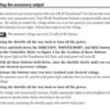
cw-80

Attachments

Images (1)
  • cw-80
Originally Posted by stan2004:

For the LEDs - including the infrared ones - it's pretty safe to assume the flat side is the "-" side (a.k.a cathode) and the rounded side is the "+" side (a.k.a. anode).  Unfortunately, for the photo-transistor I've seen it both ways.  What photo-transistor did you get?

hmm well I meant connecting them to the diagram. How would I know which part is positive or negative? Ive got the same one you showed me on ebay

Last edited by nycboy

Give me the link to what you bought for the phototransistor.


For the LED, the following should help:


ogr 3mm led

But to make a guess for the phototransistor, go with the "+" side as the longer lead and the "-" side as the short lead.  The "+" side would be the collector and the "-" side would be the emitter - refer to the 2N3904 symbol.

Attachments

Images (1)
  • ogr 3mm led
Originally Posted by stan2004:

Give me the link to what you bought for the phototransistor.


For the LED, the following should help:


ogr 3mm led

But to make a guess for the phototransistor, go with the "+" side as the longer lead and the "-" side as the short lead.  The "+" side would be the collector and the "-" side would be the emitter - refer to the 2N3904 symbol.

Perfect! and this one right here http://www.ebay.com/itm/200981...e=STRK%3AMEBIDX%3AIT

Put DMM into Resistance or Ohms mode.  Attach red and black meter leads across photo-transistor.  In one orientation, the reading will be very high and will change little if aimed at a lamp, out the window, etc..  In other orientation the reading will be much lower...and will go lower if you aim the device at a lamp or other light source.  When you find the latter case, then the red meter lead is connected to the "+" side (collector) and the black meter lead is connected to the "-" side (emitter).


Then report back whether the flat-side of the case is "+" or "-". 


Or you can email the eBay seller and ask them which is which.  Sometimes they'll even send you a datasheet which makes you wonder why they didn't include it in the listing in the first place...

Originally Posted by stan2004:

Put DMM into Resistance or Ohms mode.  Attach red and black meter leads across photo-transistor.  In one orientation, the reading will be very high and will change little if aimed at a lamp, out the window, etc..  In other orientation the reading will be much lower...and will go lower if you aim the device at a lamp or other light source.  When you find the latter case, then the red meter lead is connected to the "+" side (collector) and the black meter lead is connected to the "-" side (emitter).


Then report back whether the flat-side of the case is "+" or "-". 


Or you can email the eBay seller and ask them which is which.  Sometimes they'll even send you a datasheet which makes you wonder why they didn't include it in the listing in the first place...

Well the receiver/phototransistor has one long leg. Ill assume thats the anode? and What about the symbol for the phototransistor? Still dont know where + and - is on the diagram for it 

ogr ir photo output

Two pins on typical NPN IR phototransistor referred to as Collector (+) and Emitter (-).  DMM method described earlier will tell you which is which on a loose part.


Or email the seller and ask.


If you have the rest of circuit already wired up, you can just hook up the phototransistor and see which orientation "works".  For example, measure the DC voltage using the DMM at point indicated.  If phototransistor is installed correctly, the voltage will be near 12V when dark and drop to a few Volts or so when light.  If installed backward, the voltage will be near 12V whether dark or light.

Attachments

Images (1)
  • ogr ir photo output

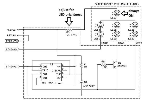
I assume you're talking about a PRR-type signal head. Is it a roll-your-own with "just" 7 LEDs wired in a common-anode configuration?  If so, then in round numbers (there are some i's to dot and t's to cross) the circuit applies with the vertical LEDs powered by the "green" circuit, the diagonal LEDs powered by the "yellow" circuit, and horizontal by "red"...and the common center LED always powered since it is always on.

But if you have a off-the-shelf PRR-type signal it likely has the timing components built-in and you don't need the timing circuit (the 555 timing IC chip) to perform the timing.  In other words, the circuit shown earlier is appropriate for a bare-bones signal head with "just" LEDs and wires as is the case with the eBay "wehonest" red-yellow-green head.

So as with most thing in life, it depends on what you have and what you want to do!  If you are looking at rolling-your-own IR detector to replace a $25 ITAD (or whatever they cost these days) with $1-2 of IR optical components to trigger the signal head, that's another issue.

Last edited by stan2004

Stan

I'm looking to drive a "bare bones" PRR type positional light signal like the 3 LED "wehonest"signal with no delay mode. Therefore, from your answer above you are confirming that the circuit will in fact apply to each 3 LED position mode connected per your "wehonest" circuit. Additionally the center LED  would remain on when the cathode is connected to -12v. I'm also assuming the R3 resistor value would be the same.

Thanx for your continued help.

Gerry G

3-aspect prr led circuit

I think I found the schematic (it's been several years!).  Anyway, I modified it for a PRR style bare-bones 7-LED head.  The circuit is the same.  Now, rather than 1 LED being on at any given time you have 3 LEDs on.  The center LED (LED7) is always on.  The resistor R3 sets the LED brightness and you can use one of those online LED Resistor Calculator programs to tell you what resistor value to use to get some desired level of current for 3 LEDs of whichever type you are using.  In practice just fiddle with different values of R3 until you find a brightness you like - it's kind of obvious when you overdrive an LED as it just seems too bright.  Something between 1K (as shown) and 330 ought to be suitable...with brightness increasing as you decrease R3.

Attachments

Images (1)
  • 3-aspect prr led circuit

Add Reply

Post

OGR Publishing, Inc., 1310 Eastside Centre Ct, Suite 6, Mountain Home, AR 72653
800-980-OGRR (6477)
www.ogaugerr.com

×
×
×
×
Link copied to your clipboard.
×
×