So, I did a feature and engine reset with everything else working but the rear coupler does not open. The sound plays but there is not coupler noise and the coupler does not open. I can manually open the coupler by pressing the center pin so I know it mechanically functions. I know it is not a big deal but if I want it to work, what do I check next?

Thanks in advance!

Original Post

Replies sorted oldest to newest

Originally Posted by gunrunnerjohn:

Since he opens it, I have to assume it's not a dummy coupler.


I'd trace the wires back to the board, it's not uncommon for those to get pinched.  If so, they may be broken, or you may have cooked the FET that fires the coupler, those are pretty easily replaceable.


Did you do a feature and/or factory reset to see if that gets it's mind right?

Yes, I did both just to be sure and nothing changed. The wires appear okay and I did not see any breaks. Where would the FET be and what am I looking for?

Originally Posted by RJR:

What is loco model number?  Is this a one or two-unit loco?  If the rear coupler in on the rear unit, there may be a tether issue.

This is the model number:           30-4187-1

It is from this set: F-3 R-T-R Freight Train Set

This is a single engine EMD style F3 Diesel engine. The instructions state nothing about the tether plug for running multiple units.

Last edited by Captaincog

That is a PS-2 3V version.  I have seen MTH use a wire nut with the purple wire and the black wire for the coupler.  Purple is the voltage for the lights, coupler and one goes to the exterior harness connector for a dummy you can attach.


So check the wire nuts.  Check continuity on the switch, and makes sure the 12 pin is fully installed.  After that, it is the fet or a trace on the board that should be tested.  G

 Do a continuity test from the two wires that connect to your rear coupler to pins 2 and 8 on the 12 pin connector on the end of your PS2 processor board.


The purple wire George talked about is pin 2 on the 12 pin connector.   I run into these often with a broken wire at the coupler.  Unlike Lionel, the MTH is fixable at that point.

Last edited by Marty Fitzhenry

Jeff, it appears you've only made visual inspections.  Do you have an electrical meter to make the continuity tests suggested?


If so, I'd first measure the electrical integrity of the coupler itself.  The MTH couplers I've seen have easily accessible solder blobs on the coupler assembly.  The resistance measurement reading should be a low number - around 2-3 ohms as shown.
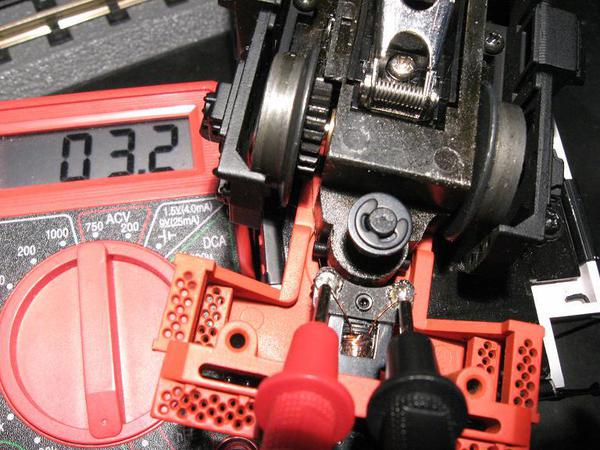
 

ogr mth coupler solder pads

If you get this reading at the coupler itself, you should get the similar reading where the 2 wires to the coupler attach to the PS2 board on the 12-pin connector (at contacts #8 and #2).  You need to insure making contact with the actual metal crimp inserts in the housing with the meter's probe tips.
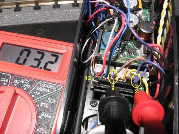
 

ogr mth coupler 12-pin

If you do not have a meter, I purposely used a "free" Harbor Freight meter to show you don't need anything fancy.  I looked at your zip and it appears there are several near you.  You've probably seen these coupons in the Sunday paper. 
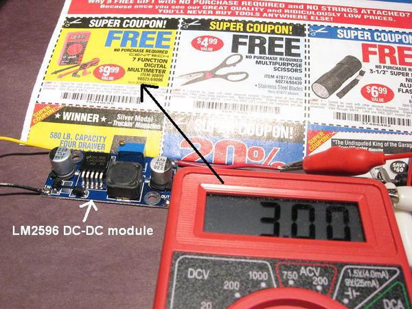
 

ogr hf meter 3v


Attachments

Images (3)
  • ogr mth coupler 12-pin
  • ogr mth coupler solder pads
  • ogr hf meter 3v
Originally Posted by gunrunnerjohn:

Thanks Marty, I'd appreciate that.  I was surprised when I went to look for them and they weren't noted on the location diagram for the other lighting transistors and FETs.


John, Look again.  The 3V fets are listed.  It is on the inside near the relay.  5V are not listed since it is a single dual FET and not really reachable. G

1 step fwd and 2 steps backwards.  Your right the electronic version posted on the MTH tech site is missing it.  The book I have from the course a few years ago clearly list it.


So much for the digital age and lack of version control, when the tools clearly make it so easy to do.


Back in my day, there would have been a clear side bar indicating any revision, a page revision date code and a Revision page documenting the changes. All done by hand.  So much for toy train documentation  G

Add Reply

Post
The DCS Forum is sponsored by

OGR Publishing, Inc., 1310 Eastside Centre Ct, Suite 6, Mountain Home, AR 72653
800-980-OGRR (6477)
www.ogaugerr.com

×
×
×
×
Link copied to your clipboard.
×
×