The switcher when it has no load draws almost nothing idling, around 250uA.  Are you talking about dropping the resistance of Rtop and Rbot low enough to draw that kind of current?  I don't know if that would cause consternation for the switcher.  In looking at the datasheet, it does appear that would probably not change anything else about the circuit, it's an interesting idea.

I think I'll stick a 1K resistor across the battery outputs and see where the charge voltage stops.  Maybe 15ma or so across that diode will keep the voltage down a bit.

Well, I have to get it working and find out what it will cost to get them assembled.  There are enough components on these that I don't fancy doing the whole job myself for any quantity of them.

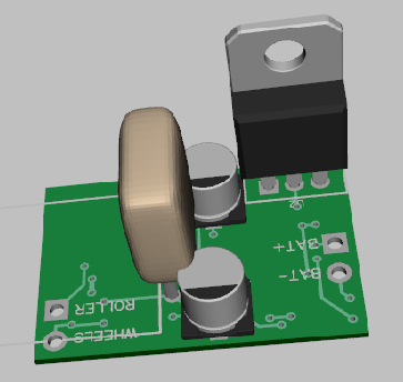
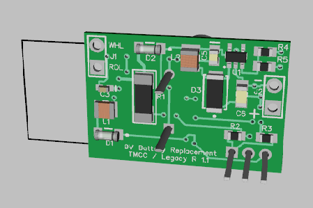
Here's my rework with the LM317, the extra capacitor, hopefully ready to order another set of boards.  I also relocated some components to allow for easier hand assembly, several components were very hard to solder with the old layout. 

I'll do some more testing before I order new boards to make sure everything is shipshape.  The regulator obviously folds down over the board, and the supercap folds out to the left onto the board as well, but I didn't have a 3D model for one like that.

Powered BCR Clone Rev. 1.1 3D N1Powered BCR Clone Rev. 1.1 3D N2

Attachments

Images (2)
  • Powered BCR Clone Rev. 1.1 3D N1
  • Powered BCR Clone Rev. 1.1 3D N2
Last edited by gunrunnerjohn

Well, the boards or perhaps a kit is likely how this will be done.  If there was really a LOT of interest, I'd look into getting a run of 100 or so done.  It's just that the tooling kills you on the first run, that runs up the cost.

I cobbled up the LM317 circuit and tested it, and that solves the problem with the over-voltage on the supercap, so that's one issue out of the way.

It's looking like a kit would be in the 16-18 dollar range with all parts and the PCB.  I'll know more when I get the updated boards and run the reworked design through it's paces, but I don't anticipate any issues with the minor changes being made.  I am pleased that it works as well as it does, I wasn't sure when I first powered it up with the missing jumper!

Basic instructions will be provided.  

Remember guys, these are surface mount parts, they look big in the pictures, but you need to have the skill to solder some fairly small components to make this work!

I'm thinking back to something Stan had said, he thought the battery clip soldered to the board would work well.  As it turns out, the size allows me to consider that.  I'm going to put a couple of PCB fingers on the board spaced right for the Keystone battery clip.  It should be possible to solder that down and after heatshrinking the whole module, just have that project from the end.  The whole thing will actually perform like the 9V battery just with a couple of wires for track power dangling out.

Don't let surface mount scare you. I tin the pad then flux paste the part and stick it to the pad apply heat with clean iron. You don't want too much solder. Use good lead solder, screw that lead free stuff. It doesn't wet out or flow like lead. When finished wash board to remove flux blow dry with high pressure air. 

If it's a fresh PCB, I just tin a pad with multicore or similar pb/sn solder and solder one side or lead of the part to hold the part in place. Then finish up with the rest of the part. Usually just relying the flux in the solder. If I get too much flux anywhere, I just clean it with a Q tip damp with 70% isopropyl alcohol.

I do something similar to Chuck.  I put a dab of solder on one side, and then heat it and slide the part in place.  If it's not flat on the board, I'll just hold it down with the tweezers and apply a little more heat.  Then I solder the other side.  For multi-leg parts, I solder one leg down with the part correctly aligned, then do the rest.

My weapon of choice is 99% isopropyl alcohol and an old toothbrush.  The 70% usually has oils and/or fragrance, so I'd pick at least the 91%.  The toothbrush allows me to knock off any flux.

There is one caveat with these boards when used to replace a 9V battery. (maybe)

The board you're using them with MUST have a common AC and DC ground.  The RS-4 and RS-5 modular boards do, and I'm presuming the RS-5.5 and RS-6.0 boards that still use the standard modular power supply do as well, given that the RS power supply card does. 

EDIT:

Note that this has changed with the addition of a diode to the circuit.  It seems that the new RailSounds boards have a bridge rectifier on track power and the internal DC ground is the negative leg of the bridge.  With the addition of one diode on our ground input, we duplicate that diode and our DC ground is now the same as the new RailSounds board, and it's still compatible with the older board.  You still have to be sure that the application you're using it for has AC and DC grounds common, or separated by one diode drop.  That seems to cover the intended target audience.


Last edited by gunrunnerjohn

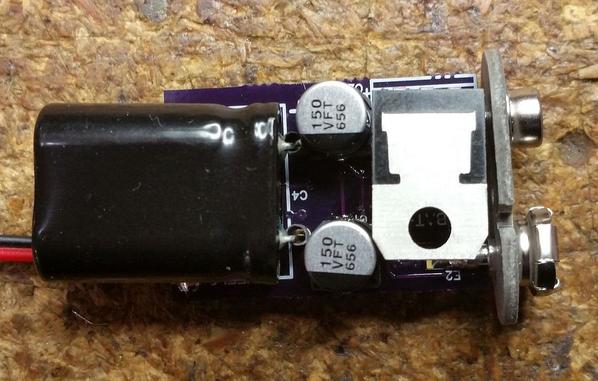
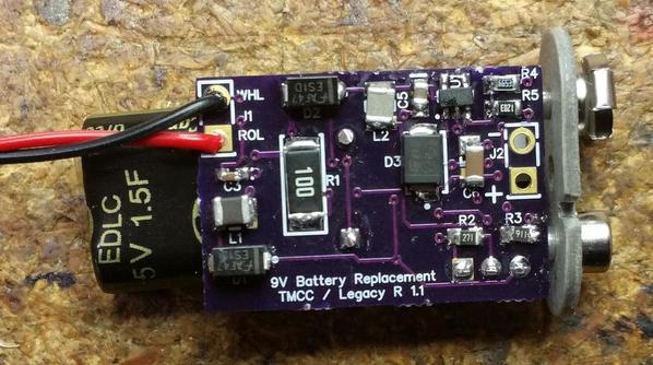
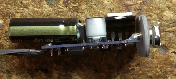
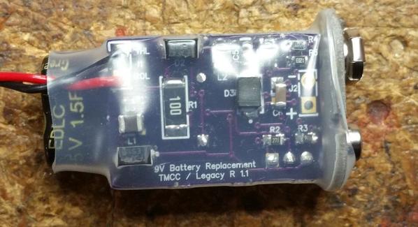
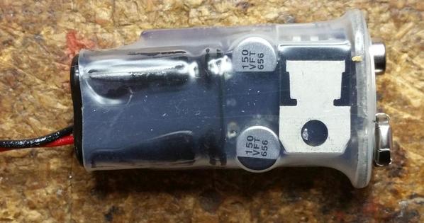
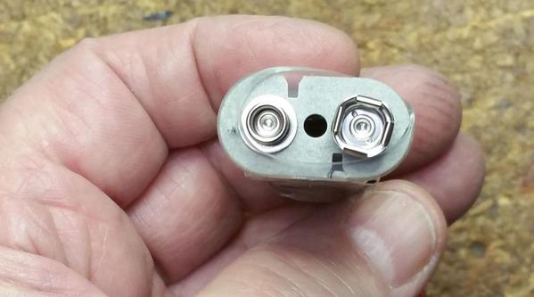
The deed is done, at least as far as I can see.  The voltages all come out right, and it works great for a conventional or command locomotive.  It also appears to have met all the size targets we talked about.  I even made it like the 9V battery as Stan suggested, so you just snap it in and find track power to charge the battery.  I've also attached the Gerber files and BOM.

I connected it to my test bench TMCC rig and tested it for command with power interrupts and shutdowns, it easily survives any typical track power glitch and more.

I then tested it for conventional operation, and it could handle multiple quick power cycles to reverse multiple times with the test stand voltage set at around 10 volts.  Turn power off, and you get the full normal shutdown sequence.

Rev 1.1 changes the regulator to an LM317 to allow me to fine tune the charging voltage for the supercap and make sure it didn't exceed the voltage rating.  I wasn't happy with the "too close to the margins" of the previous design.

One little 1.5F supercap packs quite a punch!

One final warning!

Warning has been mostly solved, see earlier post.  This unit is now compatible with the later RailSounds board with the circuit change described later in this thread.

You have been warned!

TMCC Battery Replacement N1TMCC Battery Replacement N2TMCC Battery Replacement N3TMCC Battery Replacement N4TMCC Battery Replacement N5TMCC Battery Replacement N6TMCC Battery Replacement N7TMCC Battery Replacement N8

TMCC Battery Replacement Gerber.zip

TMCC Battery Replacement BOM, Rev 1.1.pdf

Attachments

Last edited by gunrunnerjohn

Hmm, purple solder-mask.  I know what that means!

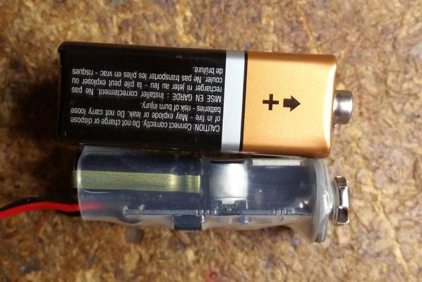
Mission accomplished; smaller than a 9V battery.

Your warnings remind me of instructions for hair-dryers which say not use in a bathtub, or not to use when asleep.   Soooo I was thinking.   Not that it would fit in the form-factor, but suppose you had one of those tiny SMT relays we've discussed in other threads.  Is it practical to have it switch between "charge" mode and "discharge" mode so that you could use this either environment?  I figure those relays would be smaller than any transformer-like isolation circuit.  That is, in principle, the supercap is either charging or discharging - you would/should never have the situation where the supercap is supplying energy if track voltage is present.  So given the small relay's response time measured in the milliseconds...i wonder


Attachments

Images (1)
  • i wonder

Yep, currently offering kits would be the only way I could do this. I don't see any way I could justify going to production on this, the up front costs are quite large. I also can't see me hand assembling a bunch of these, too time consuming.

stan2004 posted:

Hmm, purple solder-mask.  I know what that means!

Mission accomplished; smaller than a 9V battery.

Your warnings remind me of instructions for hair-dryers which say not use in a bathtub, or not to use when asleep.   Soooo I was thinking.   Not that it would fit in the form-factor, but suppose you had one of those tiny SMT relays we've discussed in other threads.  Is it practical to have it switch between "charge" mode and "discharge" mode so that you could use this either environment?  I figure those relays would be smaller than any transformer-like isolation circuit.  That is, in principle, the supercap is either charging or discharging - you would/should never have the situation where the supercap is supplying energy if track voltage is present.  So given the small relay's response time measured in the milliseconds...i wonder

Stan,

I just wanted to make sure people really saw the warning about the common grounds.   That's the most vexing issue, I really would like it to be a universal solution.

Ideally, I'd find a isolated switcher circuit, since it's running at a higher frequency, the transformer would be much smaller to achieve the isolation.  Also, having the unit be able to charge and discharge simultaneously gives it a wider application base, you can use it to power some low powered sound board or other accessory as a pass-thru and then to hold up the voltage for power interrupts.  The relay would be my second choice, it makes the battery eliminator more limited in it's application.

I haven't found an isolated switcher circuit that was small enough for the job yet, so the relay may be it.  If anyone has an idea of a switching circuit that offers isolation, I'm all ears.  The one I'm using is pretty small, I'm probably not going to find something that small.  However, it just has to be small enough to squeeze into the form factor, and I still have room on that side of the board.

I could use the J-Lead model of the IM relay I use for other projects to minimize the footprint, but it's still kinda' large.  I'll have to think about how it would fit and still keep the size in check.

Attachments

Images (1)
  • mceclip1
Last edited by gunrunnerjohn

Stan, I looked at the relay solution, but there's somewhat of a chicken and egg situation.  Pulling the relay in when power is turned on isn't a problem, and there is no critical timing there.  However, turning the relay off when power drops is somewhat problematic.  It's not like we can instantly sense track power is gone, and we also have a DC coil on the relay that I need some sort of small cap to prevent relay chatter.  Given those timings, the time for the relay to drop out can easily be 20-30 milliseconds, more than enough to cause a glitch in the sound card.  I thought of an AC relay for a slightly quicker response, but I didn't find anything remotely the size we need for this project.

Any suggestions how to instantly determine track power is gone?  Of course, it has to be done with a minimum of components as well.

I also looked around for isolated switching power supply designs.  I can find a bunch, but so far they're all too big when assembled to solve the problem.  Some of them also used pretty expensive components, so that was another turn-off.

You identified the elephant in the corner with the relay method which is low-voltage conventional where power flows thru the tandem step-down step-up.  An alkaline would deliver in this environment so if going through the effort of making a universal solution, the relay may be a dead end.

I think an isolated dc-dc converter with the power density is do-able though I think a lot of pencil sharpening would be required. Of course there are off-the-shelf modules but they are somewhat expensive and my guess is any particular module would require a bucket of components to match the unique voltage/current envelope of the TMCC battery replacement application whether it be on the charging or discharging side.  Hence, I'd think it need be a custom design...but even if such could be done, I'm not sure the average guy could assemble it if offered in kit form.  For example here's one of the 800 pound gorillas of the isolated DC-DC module market.  I don't think I could assemble that even when my eyesight was at its peak!

dc-dc isolated

So perhaps the way forward is two designs and assume that the user installs the correct version in the correct chassis type.


Attachments

Images (1)
  • dc-dc isolated

I have no problem finding isolated power converter designs and modules, the problem is finding one is cheap to build, or a module that's cheap and small enough to fit into the space we have.  None of the isolated modules I've found that are under $10 come anywhere close to the low voltage 2-2.5 volt input and the 8-9 volt output I need for this design.

I couldn't come up with any way to make the relay work, though maybe there's something I'm not considering. 

I'm not sure what the comment about two designs means, I have yet to come up with a workable solution to the isolated ground scenario.  If I could build an isolated one, that would be "the" design.

I was imagining the isolation on the charging (input) side.  In other words you have a circuit (including supercap) that emulates a 9V battery.  That this "battery" has a 5V supercap inside with a step-up regulator is irrelevant.  So then I figured the chore is to charge this "battery" using an isolated charger sort of like the smartphones that can be charged without plugging them in (i.e. isolation on the charging side).  As before if this must operate in the pass-thru mode with battery augmenting track power in low track voltage conditions I don't see how a relay can work.  So the two designs would be the one you have now for the chassis=ground applications, and then another to-be-determined design that (apparently) may need to be bigger, in 2-parts, whatever, for applications that need chassis isolation.  In other words you don't have a "universal" design but at least you have a shovel-ready design that will work for the original intended application.  Glass half full.

I don't disagree.  But the problem is whoever design O-gauge in the first place made the annoying decision to use 60 Hz.   Transformers are just too big at such low frequencies.  I think the hit must be taken to convert to DC, then use a switchmode isolated converter running at 1 MHz (or whatever) so that the inductors/transformers can be proportionally down-sized.


Just to throw something out there, do the boards that would require an isolated supply have somewhere else where input power could be tapped from rather than using track power?  For example on a LionChief engine, filtered, rectified, unregulated, DC can be taped from the smoke-unit plug and shares common ground with the rest of the electronics package. If the legacy boards use a similar set up to power the smoke units, one could tap in there and share a common ground with the electronics that is already isolated from the input AC and chassis.  

JGL

stan2004 posted:

I don't disagree.  But the problem is whoever design O-gauge in the first place made the annoying decision to use 60 Hz.   Transformers are just too big at such low frequencies.  I think the hit must be taken to convert to DC, then use a switchmode isolated converter running at 1 MHz (or whatever) so that the inductors/transformers can be proportionally down-sized.

The reason I was looking to do the isolation after the supercap is precisely the reasoning you are using, the inductors would be a whole lot smaller.  I just haven't found a suitable design for the boost switcher that will fit and is cost effective.

JohnGaltLine posted:

Just to throw something out there, do the boards that would require an isolated supply have somewhere else where input power could be tapped from rather than using track power?  For example on a LionChief engine, filtered, rectified, unregulated, DC can be taped from the smoke-unit plug and shares common ground with the rest of the electronics package. If the legacy boards use a similar set up to power the smoke units, one could tap in there and share a common ground with the electronics that is already isolated from the input AC and chassis. 

No offense, but this is a non-starter!  The whole point here is having a PnP battery replacement.  Hacking your $100+ RailSounds board to make it work isn't likely to be received well.  Also, if you look at the modern RailSounds board, the only power supply is integral to the board, there is no convenient place to grab ground referenced power.  This is a unit for people that don't play well with fine pitch surface mount parts!

gunrunnerjohn posted:

No offense, but this is a non-starter!  The whole point here is having a PnP battery replacement.  Hacking your $100+ RailSounds board to make it work isn't likely to be received well.  Also, if you look at the modern RailSounds board, the only power supply is integral to the board, there is no convenient place to grab ground referenced power.  This is a unit for people that don't play well with fine pitch surface mount parts!

I guess that was my point, in the example LionChief board, one could make a connector that plugs right into the board with a pigtail to plug the original connector into, thus requiring absolutely no modification to the thing.  If the boards in question don't have any such connectors or anything like that, then yes, the idea won't be practical. Don't suppose you have a close-up of one of these boards to look at?

JGL

gunrunnerjohn posted:

It's the bridge rectifier that supplies power that causes the problem.  The DC ground is not frame ground on all the new Lionel/ERR Sound board products.  I presume the battery is connected to DC ground internally, but it really won't matter if we figure out an isolated supply scheme.

Well, if we knew for sure how the new Lionel/ERR stuff was wired, you might be able to do something like the attached. Note that the added rectifier parallels one of the rectifiers in the bridge.

Attachments

Add Reply

Post

OGR Publishing, Inc., 1310 Eastside Centre Ct, Suite 6, Mountain Home, AR 72653
800-980-OGRR (6477)
www.ogaugerr.com

×
×
×
×
Link copied to your clipboard.
×
×