Building a turntable from scratch. Does anyone have any info on motors.
Have never messed with motors before so I have no idea where to start on ebay or amazon
Thanks
Bob


|
|
Building a turntable from scratch. Does anyone have any info on motors.
Have never messed with motors before so I have no idea where to start on ebay or amazon
Thanks
Bob
Replies sorted oldest to newest
Lots of approaches. Knowing the how the build is planned to look would help.
Serious model with center shaft driven bridge/table. Toy-ish Lazy Susan & motor with a friction wheel drive?
Center shaft driven bridge/table would be my choice.
Robotics hobby sites should have good options for high torque, and slow exacting control.
My gear motor reference wont be cheap, or easy to look at comparisons from different industries...Grainger, has a great paper catalog, but online you only see what you ask for.
Low buck,
You want a high torque, low RPM gear motor. Very low. Like 2rpm would be fast Id think.
You can add a single gear to the reduction box output, and one to the tables shaft in order to get another reduction as you mount it.
To line up the table easier, with more exacting control, use a stepper gear-motor.
Exacting control of a stepper by an opto wheel, allows hooking to electronic control boards that can count those and remember where to stop.
or button(s) to turn the table non-stop, and another (2?) to "jog" individual steps.
You still want gears on a stepper to avoid jerkiness as it steps.
A little more involved. Diamond Scale supplied a 80 to 1 gear reduction drive. and a drive motor that would slow the system to something that worked well.
Turntable build project. Click on the underlined.

Smaller Diamond Scale TT on my layout. The larger TT is part of the Fort Pitt Highrailers modular layout. Click on the Triangle.
it is going to be a 30" deck with pit. I have started with a 5/16 threaded rod on skate board bearings and a 18" wooden round that would be spun by dc motor. Motor powered by HO DC power.
Was going to use detents to align track as inexpensive start.
How much is a DC stepper motor and electronics, anyone have model number that has worked for them?
Not to far along to change or modify design. Any inputs would be most helpful
Thanks
Bob

Mike, That is some build. Was that a Kit? Did you custom Rivet all of the brass?
Extremely impressive, how long did that take?
Bob
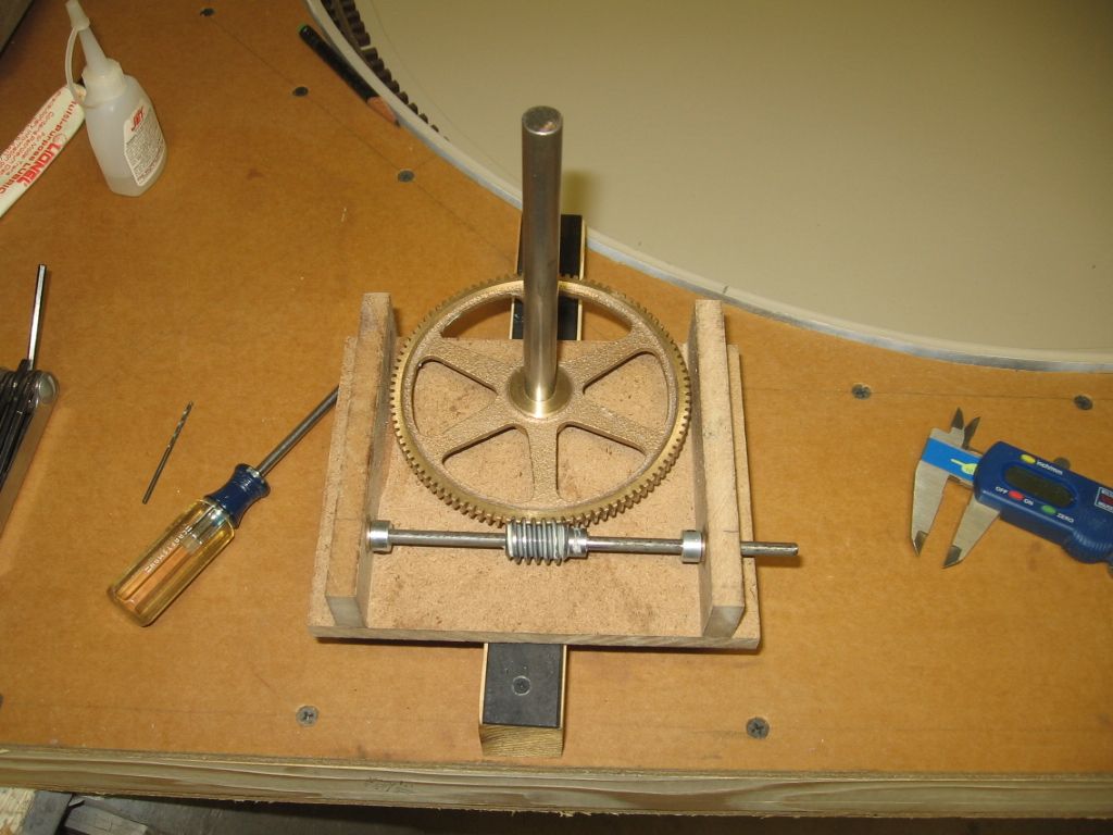
Mike, That is some build. Was that a Kit? No, there are parts from Diamond Scale and Parts from Bowser. The worm Gear pictured was from Boston Gear. Bearing used for the bridge boogies were acquired via the internet. A local fab shop did the drive shaft, bridge side frames, and pit circle. Did you custom Rivet all of the brass? Yes, there should be detailed pictures using a North West Short Line Sensi-Press with the Riveter table.
Extremely impressive, how long did that take? Way too long, it's a hobby. ![]()
Bob
A Lazy Susan it is.
My experience is more along the lines of vending, gaming, & entertainment than a turntable. Every machine is different. There is too much time gone by, and variations used to say "that one" without pointing you at a high dollar industrial version.
The "best" suppliers change.
The base motor tech exists, and it is what you make it![]()
RPM, torque, and hold values required, have a lot to do with the price of any motor.
I don't really know how much is torque is enough here, do you?
My concern is if the shaft area on yours is holding all the thrust.
The table needs to have zero vertical run out, at the edges, no tipping.
A full bridge, and the bearing mounting alone holding it, may have enough flex to tip a few thousandths.. A few thousandths in the center can give you 1/16th rise and fall at the disk edge. The pit rails work to allow it not to be too tight at the center, but keep in aligned for rail height. I think that's why many just go the extra mile to use them.
The shaft should only center, or maybe drive the disk. Support the outer edges of the disk with rollers/slides to prevent any tipping. Pit rails aren't just for looks.
A geared step motor wouldn't be real cheap, but would work well for indexing.
Range from $15-$300 , for one.
Another $30-300 for controls. Arduino stuff is out there too.
The good TT systems likely use one like it.
With the right motor on it, Mikes gearing looks strong enough to turn a washing machine.
A 360 RC servo motor is an alternative you might like. Cheaper to buy, simple, strong.
There are lots of ideas and options here. You might find cheaper by looking yourself, this was my first stop & first look around in a while. This panning motor kit here is actually expensive at around $80 as far as options go here.
You can find chain drives, gears, hubs, frames, etc etc too. Plastic or metal.
https://www.servocity.com/html...l___accessories.html
I've never done business with these guys, rep. unknown.
This if for you to see there are lots of options
On the "half done, low end"-
A cogged, synchronous drive belt and pulley would be "cheap gearing" and they have it.
If the ho motor is not strong enough, just buy a bigger motor and re-adapt.
Being unsure of the budget, and of the skills you have at cobbling together some parts this may or may not be for you. If you have the $$ to spend, others have offered good suggestions. if you're working on the cheap, however, my recommendation is a power window motor out of a car. Choose something like a toyota camry motor and you'll never have to worry about availability if it breaks. New window motors cost about $40-60, and used from a junk yard, less than half that.
You'll need some further gearing and a control system, which will add some $$ as well, but for a more or less bullet proof high torque motor, the price can't be beat on the junk yard variety.
Then again, it may be much more motor than is needed to move a turntable.
Some where in my foggy head I remember a detailed parts list I had posted. Turntable build project.
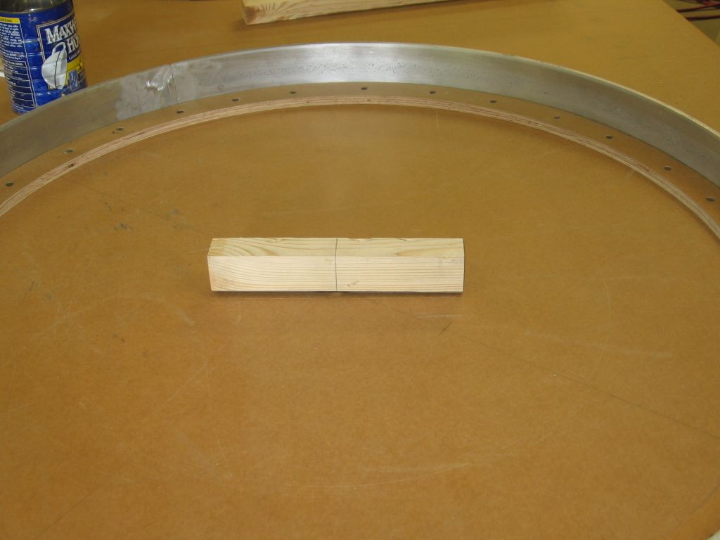
Aluminum Ring, bridge sides, and pit rail bogies/wheels, were fabricated, local fab shop.
Good quality White fir framing material for the module, with MDO board use as the surface plywood.
Parts list as follows. Note: As the building part of the hobby seems to be contracting/shrinking ,some of the following list of venders, and materials may not be available. IMO.
Thanks for all the info.
My budget is a couple hundred. Which probably means a couple hundred more than I had originally thought. lol.
Im going to try and build it out the way I had planned, Im new to this so it will be good experience.
Im going to research the servo motors first. I think they will be the easiest to implement into my existing design.
The parts list will prove invaluable to get it looking and operating. Thanks so much for all the input.
Will keep ya posted, and probably some more questions. lol
Bob
Stepper motors and drivers can get expensive. After wasting a bunch of money on what I thought would be cheaper alternatives, I settled on the drive kit from Ross Switches. Easy to install, runs smoothly, and best of all can be run slowly. My own experience taught me that a belt drive is superior to a gear drive. I also used the Dallee indexer, with excellent results.
Millhouse River also has a drive kit available. I picked Ross because it comes with a power supply/directional control.
Jim
I use an antenna motor high torque low speeds
I'm using a BBQ spit gearbox that I saved after the BBQ rusted away. I changed out the AC motor for a DC motor. I then put a small rubber drive wheel on the output shaft which drives a 36" diameter wheel cut from a piece of plywood which is on the bridge shaft under the pit. This further increases the drive ratio but more importantly eliminates any gear lash.
Save your money and buy a MHR unit. You'll thank yourself later.
Man, in my youth, I worked in a hardware store, and we got a new paint tinting machine one day, and the boss said through the old one out, or take it home. The old one had about a dozen cylindrical reservoirs to hold the respective color of tint, each with their own low speed, hi torque sealed 110V grounded motors, sealed in an aluminum cap, with a slotted shaft for the mixing shaft, which was attached by a steel collar with a recessed set screw. Each of the motorized units had a grounded 12" cord. i stripped them out of it, and held onto them for I don't know how many years (decades even ), I had 'em in a box. Through a couple of moves, they became lost to me forever. What I'd give, to have them today. The good news is, some of the independent hardware stores, still have those paint tinting machines. If I still had them, I would gladly send you one on the house. They were supposed to be for future animations on my train layout, and a motorized turntable was in the mix. They would have been just the ticket, except for the indexing part. Good luck Bob, keep us posted on your progress.
The turntable motor from a microwave is very low speed (6 rpm) and will support a substantial amount of weight. Only downside is it is non directional, meaning it could rotate in either direction with power (AC) applied.
On a historical note, many turntables were Armstrong type. This meant they were hand powered and that is certainly the easiest build for a layout. Even the large indoor turntable at the B&O roundhouse is hand powered.
Ive got a microwave motor somewhere. Ill poke around later.
6 rpm is way too fast. That'll take 10 seconds to make one revolution! I don't know what a real turntable does in rpm. I saw the one at Steamtown operate but I don't recall its speed. Maybe someone can chime in here. I did measure mine and it takes 80 seconds to do one rev. And even that is too fast to stop and line up. But I use an old N gauge power pack that has a throttle handle so as I get near the track I want to line up with I can slow the speed way down.
Bob, one tip. A weak point is where the shaft is connected to the turntable table, and another where it connects to a drive wheel. Set screws tend come loose. Better to drill and use a thru pin (even a nail or brad),
Thanks again for all the input.
Would love to buy MHR completed TT but don't have the budget a the moment. Do they sell their motor and indexer separate? Then add them back to one of their completed kits later if I can find the coin.
Does the Dallee indexer work with any rotary spool and stationary stanton type setup to visually index?
Matt, Looked on McMaster Carr page. Is this along the lines of what might work? If so how many RMP max? What is the MRC power pack? Is that used ton control motor?
http://www.mcmaster.com/#electric-motors/=xqlj8k
Just found the MRC power packs, they are DC so I guess I would need a DC version of that motor. Like this one?
http://www.mcmaster.com/#electric-motors/=xqlm3d
Thanks agin
Bob
Matt, You had originally mentioned the 24v motor. Looks like the 12v has about the same torque. Any reason for the 124v? How many volts do the MRC packs put out? Will the MRC be able to reverse this type of motor?
Any DC motor will run in reverse if you just switch the polarity. I suggest a 24V motor because you will get a slower operating motor by putting less voltage to it. so If you get a 24V 4 RPM motor it will run at about 4 RPMs at 24V, 2 RPMs at 12V, 1 RPM at 6 Volts, and .5 RPMs at 3V. you can get a 12V motor but you have a narrower operating range and you will get tthe 4 RPMs at 12V and the 1 RPM at 1.5 V. It can be difficult to get the cheaper MRC power packs to go below around 3 volts and maintain
Have you considered a windshield wiper motor from a junk car?
Have you considered a windshield wiper motor from a junk car?
I see that my last post was incomplete.
A windshield wiper motor is 12vdc and reversible. The wiping action is accomplished with a lever on a pivot with the motor rotating slowly in one direction. The motor speeds are easily controlled, on the older wiper motors with a robust resistor, and they usually have a mondo radial bearing, keeping the geared drive shaft securely located and capable of absorbing varying axial forces. Coupled with an inexpensive vertical thrust bearing, (a Lazy Susan style from any hardware store) and a cup of ingenuity,it might work. Or, you will certainly hate me for this dirt road, and ask that I be catapulted from this forum.
"it is going to be a 30" deck with pit. I have started with a 5/16 threaded rod on skate board bearings and a 18" wooden round that would be spun by dc motor. Motor powered by HO DC power.
Was going to use detents to align track as inexpensive start."
I've built them that way, a plywood disc the same diameter as the bridge( the bigger the disc the better the control and smoothness) is mounted below the pit and powered by a gear head motor with rubber wheel running on the edge of the disc. The motor is DC and can use an old HO scale power pack for power, speed and reverse. The HO power pack gives good low speed control so the bridge rails can just be aligned with the stall rails by eye in O scale. Bowser used to sell similar turntables and the motors, end of bridge wheels, bridge castings ,etc. I thought I still had one of the gear head motors with wheel around here but I can't find it right now. You might do a web search for that description and see if any turn up. I used to see them on ebay occasionally.....DaveB
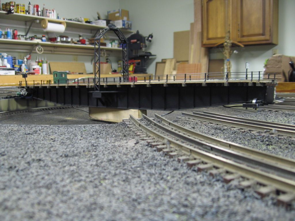
One of the primary concerns of a TT is the side-ways, bending, torque on the center turn shaft. As the weight shift toward the ends of the bridge, the thrust bearing, center shaft tends to bind. Bowser TT even had issues with the center shaft bending. The Diamond Scale design allowed the bridge to float/not directly connected to the drive shaft. All the bridge weight and locomotive load were shifted to the pit rail and pit rail bogies, like the real turntables.
The drive only had to turn, not support weight. Keep this in mind as you build your TT's
Note the slip fit of the bridge over the turn mechanism.
Bridge in place.
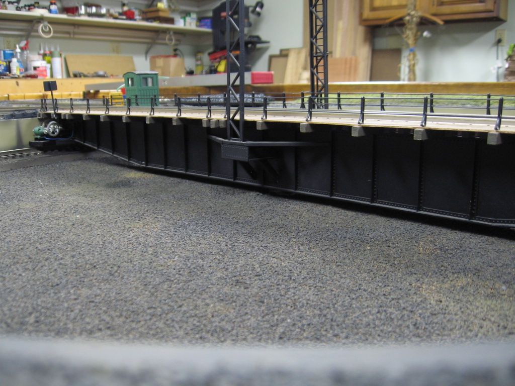
The bridge can be easily lifted-up-off the drive block.
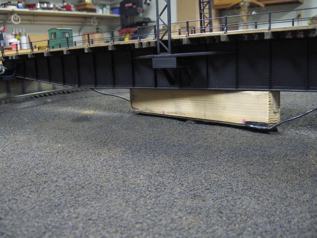
You want the weight on the pit rail bogies.
Best wishes with your project. ![]()
![]() Mike CT
Mike CT ![]()
572 ci 720 hp motor? Old school. Chevy has a 454 ci LS crate motor at 770 hp. Anyway I used a 6" diameter pulley from hardware store on my 5\8" shaft to attach the 36" diameter plywood drive shaft to. On my previous layout I had a 48" drive wheel. With a 30" bridge and pit I had the pit about 8" from the layout edge. On the layout fascia there was a slot about 12" long by 1/2" through which the edge of the drive disc protruded about 1/2". You could then move the turntable manually.
I would just use a gearmotor and belt drive configuration. High torque is not needed when geared down. The torque will be multiplied by the gear reduction. Put your money in quality bearings including a thrust bearing to support the table. You should be able to spin the table around with your little finger with little effort.
Pete
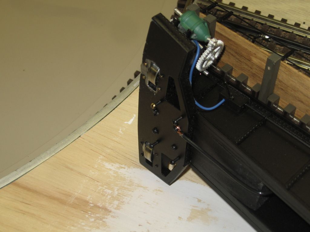
If the weight is distributed to the pit rail, the thrust bushing/bearing only involves turning. This is the one I used, with a 7/16" shaft. The thrust bushing is also used as a 360 degree, moving, electrical contact, center rail on the bridge.
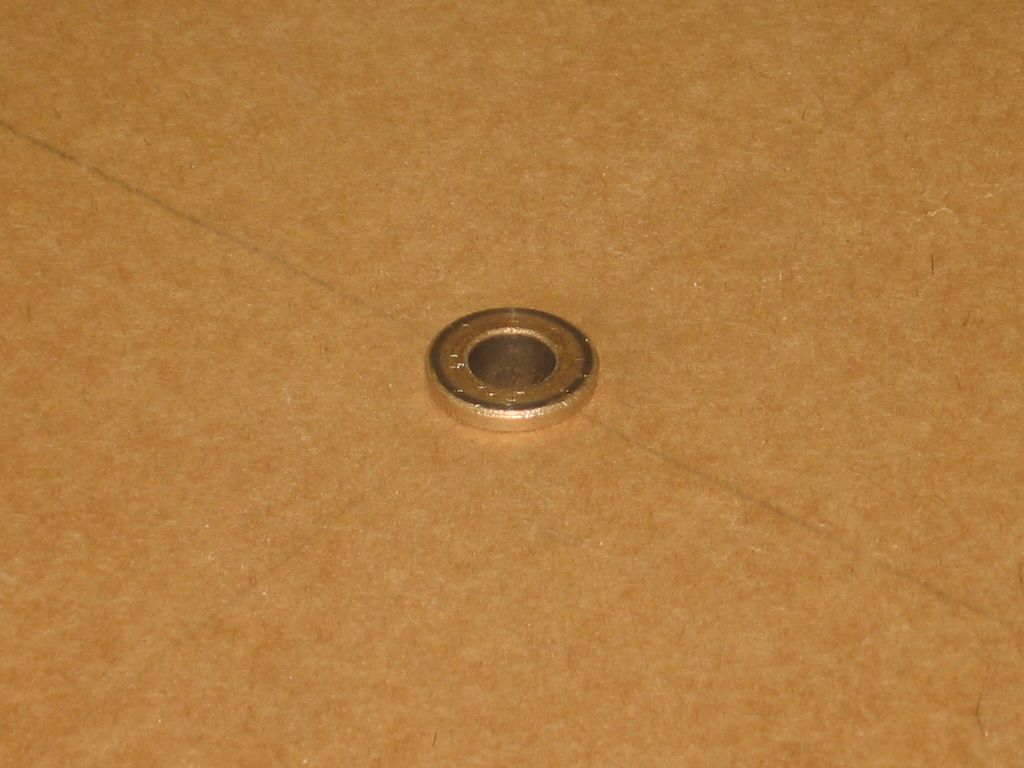
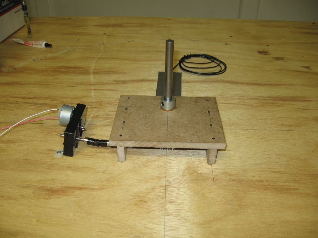
Shaft and floating drive assemble position in the bridge upside down.
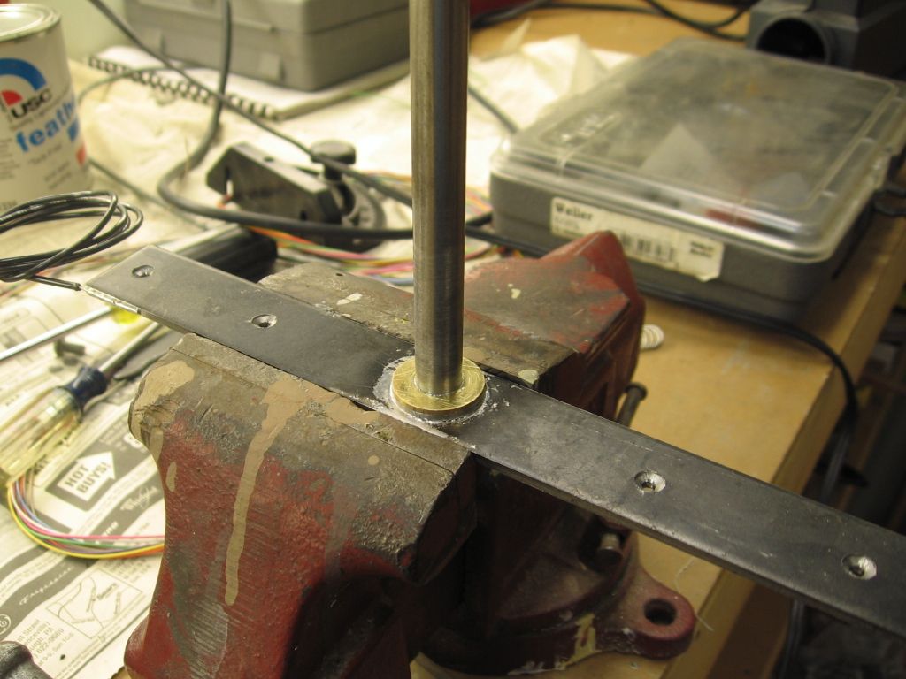
Drive block.
I also added a couple brass washer to the shaft. Brass on brass electrical connection.
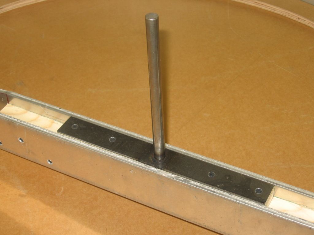
Drive components with the shaft and T-bar assembly. Again upside down without the pit.
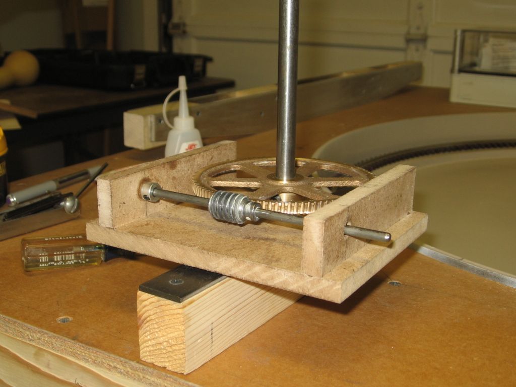
Caution: The Boston Gear worm and screw are an 80 to 1 reduction. Attached to the drive motor box assembly, there is addition gear reduction and at the same time increased torque. Original thought was to through-bolt the brass gear to the shaft. I only used a set screw, to the shaft, which allows the bridge to slip if the bridge is bound in the pit some way.
Diamond Scale TT's used a roll-pin gear attachment that did not slip. One occassion it did bind, I was lucky with minimal damage.
The high torque, associated with slow turn speed, applies considerable force, even though you can be using a small electrical motor.
Something else to consider is getting power to the turntable rails. here's the way I did it. The outside rails on the turntable are wired to the bogies that ride on the pit rail which is wired to common. The center rail gets power in a prototypical manner. There's a pole off to the side of the pit (not visible in the photo but just off to the left) that has a wire going to the center structure on the bridge. There's a wire that goes down to the center rail.

Gary, with the prototypical setup, what do you use on the center structure so the feed wire does not twist or get bound up? This is my preferred way to finish power to my TT when completed. Thanks for the tips from all, very helpful.
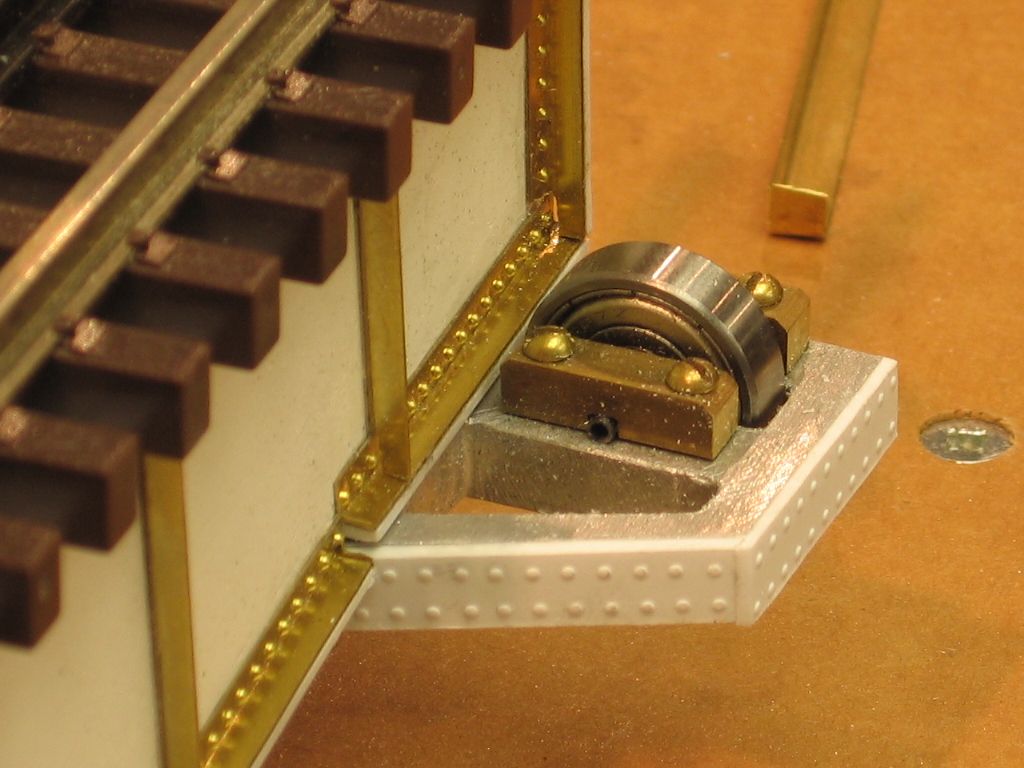
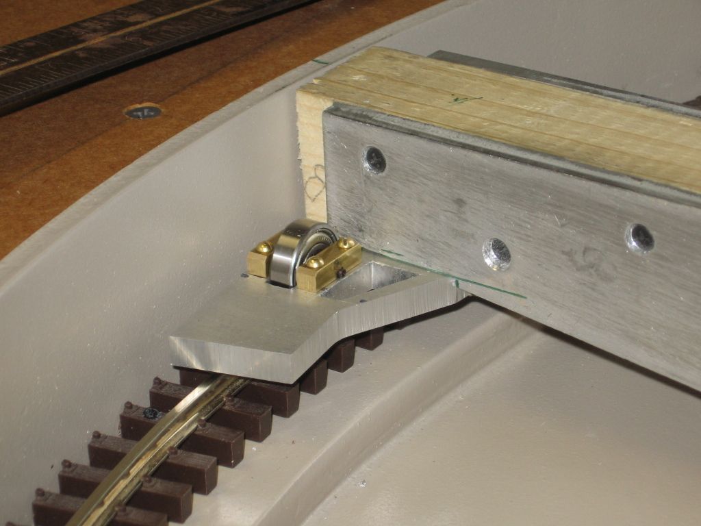
The center drive bushing is powered for the center rail from below.
Note the wire, top of picture, taped-down with duct tape, soldered to the center thrust bushing.
The T-bar assembly rest on the bushing. Note the wires that take power to the center rail. Both wires connect to the center rail.
The Pit rail wheels pick the outside rail common power from the pit rail. Note the connected wire that attaches to the outside rail on the TT bridge. Black wire bottom of picture, one from each bridge truck assembly.
Both electrical connections are a moveable. The TT can turn 360 degree with no concern about twisting wires.
I did this about 20 years ago and don't recall exactly how I did it but looking at the photo the power wire is solid 16 gauge and is soldered to assembly #1 which is a brass washer that is soldered to a 1/8' brass tube. This is free to turn inside another assembly which is composed of a 1/2' brass tube soldered to the bridge framework. Inside that tube is a plastic sleeve for insulation and then inside that is another brass tube which has a wire soldered to it that feeds down to the center rail. Assembly #1 then freely turns inside that and makes electrical contact. 20 years never a problem.

Gary, thanks for the information, this will assist me greatly. Hope you and yours had a safe and monumentous Independence Day.
Had a great 4th thanks! The BPOE (Elks) organized the parade in town (Sparta NJ) and our parade Grand Marshall received a congratulatory letter from the NYS&W (Susquehanna) railroad that runs thru town. Also one from Energy Logistics that used to haul double stacks from Port Newark to Buffalo via the NYS&W.
Access to this requires an OGR Forum Supporting Membership
