
After several years of planning and preparing, I have finally started work on a basement layout. The layout is approximately 12' by 13' (more precisely, 12' 1" by 13' 4"). The reason for these dimensions is the layout is being built on top of solid core doors, most being 6' 8" long. The doors are supported by steel table legs for shelving units. This has made construction of the benchwork move very fast with almost no cutting save for a notch where a column is located. The pieces are then strapped together from the underside. This yields a modular system that can be disassembled and transported in the future.

The plan that I had drawn up was a two-track mainline (O72 and O80), along with a yard, engine service facility, and REA freight depot that curve into the center of the layout. There is also a place for a river and a postwar 313 Bascule Bridge spanning it that I purchased from a friend.

fullsizeoutput_17e

I have had this plan drawn up for the past year or so. On Sunday, construction of the benchwork began. Here are  before and after shots.

IMG_2648IMG_2654

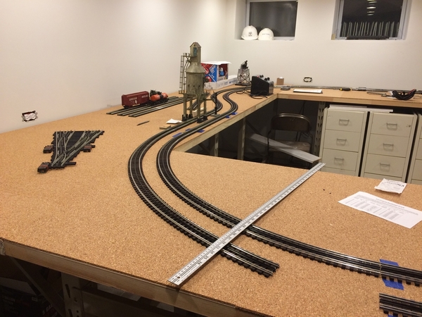
As construction on the tables progressed, things began to change. The plan called for an opening that was 3' x 6'8" where I would control the trains from. As the perimeter tables went up, the large open area in the center was calling to me. The larger opening allowed more space to move around. So, after over a year set on the plan shown above, I quickly set to work on a new plan. This plan has the larger open area in the middle with 3' tables on three sides and 30" tables on the remaining side. With the center section removed, the yard had to be relocated. I now have it sketched out to be on the 3' door along the far wall.

IMG_2655

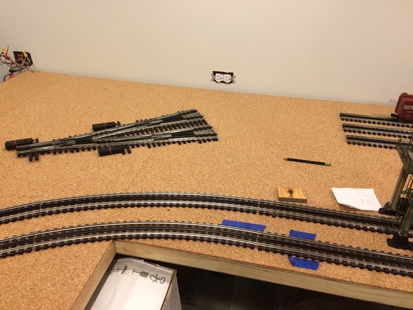
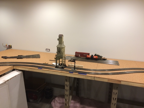
This is the new plan I drew Sunday night. It shows the rail yard and engine service facility along the left wall. I added a slight S-curve along that wall as well to break up the monotony of trains only turning one direction ( a short straight is called for larger engines/trains to traverse it better). The tables on the right have a couple industrial sidings for switching operations. Sadly, there is no place for the bascule bridge in this plan, so I will put it on display somewhere instead. This revision simplifies the track plan significantly. The previous plan had some fancy track-work on the yard throat to maximize the tracks coming of the Ross 4-way. The new plan will have much longer yard tracks and very simple track-work. I also believe this plan has longer mainlines because they do not cut diagonally across in the top left corner as they did in my original sketch. Even better, my new track plan has a much larger area for the town. The previous plan had a smaller town due to the river and bascule bridge scene in the upper left corner.

I will continue to update this thread as progress is made. I look forward to any feedback that my fellow hobbyists have to offer. Happy railroading and Happy New Year, too!

Attachments

Images (4)
  • fullsizeoutput_17e: Track Plan 1
  • IMG_2648: Before
  • IMG_2654: After
  • IMG_2655: Track Plan 2
Last edited by Harry's Trains
Original Post

Replies sorted oldest to newest

Harry - both designs look very promising! The second one is right up my alley - double track mainline, engine house, and a yard!? I'd be in heaven!

One thought, what if you connect the inter-most siding (4th from the left, closest to the main lines) to the outer main line? They are close in proximity and this would provide a 'passing siding' and also the opportunity to pull train in rather than backing them in.

I would also recommend putting in a 'ready track' for the engine house so that it's not directly connected to the mainline.

An overall suggestion, lay the tracks out and run trains for a few weeks without the track being nailed down, this will reveal any flaws that you might find in operation or shows anything that you might want to add. Doing it before nailing the track down will allow you do make slight adjustments to the design without it being a big hassle to move the track around.

I'll definitely be following along here and on your linked youtube channel!

Last edited by Prr7688

Congratulations on getting started!!  Your second, working drawing looks the best.  You need that space in the center.  I am assuming you plan to duck under to get into the center.  You look plenty young that it won't be a problem.  My layout occupies a space of 11x8 and at my age I needed to provide a lift up or lift out bridge section to get in the middle.  I'm looking forward to seeing more about your layout construction!

What is the scale that you used for your drawings? What dimensions are your curves?


Jay: the scale of both drawings 1/2" to 1 foot. The squares of the grid are each 1/4", so 1 square equals 6". I also have numbers marking the feet along the top and left sides of the plans.

The mainlines are O72 and O80. The curve going into the yard is O54.

@Prr7688 posted:

One thought, what if you connect the inter-most siding (4th from the left, closest to the main lines) to the outer main line? They are close in proximity and this would provide a 'passing siding' and also the opportunity to pull train in rather than backing them in.

I would also recommend putting in a 'ready track' for the engine house so that it's not directly connected to the mainline.

An overall suggestion, lay the tracks out and run trains for a few weeks without the track being nailed down, this will reveal any flaws that you might find in operation or shows anything that you might want to add. Doing it before nailing the track down will allow you do make slight adjustments to the design without it being a big hassle to move the track around.

Prr7688: I have considered connecting one of the yard tracks to the main line as you have suggested. At this point, I'm still not sure, however I will keep toying with the idea.

While I would like to have a 'ready track' for the service facility, I don't think there is enough space. However, the service tracks may end up being longer in reality than in the drawing.

I will certainly take your suggestion and get trains running before tacking everything down.

@Mark Boyce posted:

Congratulations on getting started!!  Your second, working drawing looks the best.  You need that space in the center.  I am assuming you plan to duck under to get into the center.  You look plenty young that it won't be a problem.  My layout occupies a space of 11x8 and at my age I needed to provide a lift up or lift out bridge section to get in the middle.  I'm looking forward to seeing more about your layout construction!

Mark: yes, I will be ducking under to get into the center of the layout.

No pictures today, but I have been getting work done. Over the last few weekends, I have been applying 6mm cork sheets over the surface of the layout for sound deadening. The sheets are 2'x3' sections. I've had to do some trimming because all the doors are 6'8" long, and two of them are 30" wide, not 3' like the rest. I only have one door left to cover, and thats the one with the column going through it, so that will be a challenge when the time comes.

Other than that, I'm waiting on a circle of O80 curves from GarGraves and the 4-way and cross over switches from Ross. I know what other switches I need, just haven't gotten around to ordering them yet.

So thats the current stage of the layout. The biggest setback is just waiting for track now. Once that comes in, things should start picking up!

Harry, congrats on taking the plunge.  I joined OGR in 2018 and have found that these folks are the absolute best in model railroading!  Have you tried out AnyRail software.  The free version could give you some help on tricky areas.  Also, I bought Jim Barrett's book (RIP Jim).  Could be good reference material for you.  Really looking forward to seeing your project grow.

Harry, the use of doors is a great idea.  They’re lighter and perhaps easier to manage in setting up.  I am developing a new layout presently, and was considering ¾” ply, but the doors might work.  My layout will be “L” shaped, about 12’x8’x48” wide on both legs.  Might mean a narrower dimension but perhaps more workable in the space I have.  Thanks for the update.  Keep us posted.

Sorry I didn't see this sooner, but just some food for thought.  As currently designed, your trains can only run in one direction after leaving the yard, and I mean always in one direction because there is no provision for turning locomotives other than "the hand of God" (YOU in this case).  In addition, there is no way for any train to service the industry off the inner main line unless it pushes those cars out of the yard, and even then, it looks like you will have to push those cars all the way around the loop before crossing over to the inner loop.

Please take the time to do some reading about model railroad operations before you start laying track.  It can be a lot of fun and helps prevent boredom from setting in while watching trains just run around the same circles/ovals.

Chuck

It's been a while since I have posted on the progress of my layout. Work has been slow with other things occupying my time, but I have made some decent progress. With the exception of one switch, all the track for the mainlines has been put together. Nothing is fastened down or wired, just put into position so I can trace out the track to lay cork roadbed, hopefully in the next few weeks.

Here are some progress photos, please pardon the mess:

These shots give an overview of the four sides of the layout. You can see in the first photo where I am waiting on the last switch to come in. This will lead off to the yard. I have been playing with how I will be setting up my yard tracks. I have a Ross 4-way at the throat. I am considering having the 4-way at an angle partway between the switch coming off the mainline and the yard tracks themselves (okay, that makes no sense in writing, so see the pictures below). This arrangement would allow for each yard track to be at least a foot longer as the tracks curve out of the 4-way. It will also help to hide a sharp curve as I plan on using O54 on the turn into the 4-way from the mainline. The one downside would be having to bend curves into the yard tracks. The geometry of the switch and the spacing I want would require the track closest to the wall to be the sharpest curve. Again, I'm still not 100% on this switch placement, it just came to me one day and I laid it out to see how it would work.

Also in regard to the yard area, I have elected to nix the engine service facility. Unfortunately, the area is just too small to make it work and look right. In the future when more space is available, and since the door modules can be fairly easily expanded, I can build a proper engine service facility. In the mean time, I have decided that my coaling tower and water column will be on the mainline itself, much like the concrete coaling tower on the old MC (I think) mainline near New Buffalo, MI/Michigan City, IN. I have used some of my passenger cars to test the clearance and it should not be an issue.

Hope everyone enjoys this update. It's been a while, but the little things here and there are gradually building up. Hope to have trains running soon!

Attachments

Images (6)
  • mceclip0
  • mceclip1
  • mceclip2
  • mceclip3
  • mceclip4
  • mceclip5
Last edited by Harry's Trains
@PRR1950 posted:

Sorry I didn't see this sooner, but just some food for thought.  As currently designed, your trains can only run in one direction after leaving the yard, and I mean always in one direction because there is no provision for turning locomotives other than "the hand of God" (YOU in this case).  In addition, there is no way for any train to service the industry off the inner main line unless it pushes those cars out of the yard, and even then, it looks like you will have to push those cars all the way around the loop before crossing over to the inner loop.

Please take the time to do some reading about model railroad operations before you start laying track.  It can be a lot of fun and helps prevent boredom from setting in while watching trains just run around the same circles/ovals.

Chuck

I would have replied to this sooner, but haven't spent a whole lot of time on the forum since my last update. I certainly thought through these concerns you raise while I was planning my layout, as they are also important to me and how I would like to operate.

Trains will be running clockwise on the inner loop and counterclockwise on the outer loop. This means that the industrial sidings are designed for a train to back in from their respective direction of travel.

In the case of the yard, a switcher will pull cars in and out of the spurs to build trains. To build a train for the inner main, the train would be built by a switcher in the yard, and brought to the inner main over the double cross-over. I have seen friends layout with similar yard setups (accessible from only one direction on one of several mainlines), and it works for them and I see no reason it shouldn't work for me.

Given the size of my layout and the surrounding space, there is no space for a reverse loop.

Harry:

Like you, I built my L-shaped O-gauge layout on door panels; in my case, hollow core - because lightweight - then covered with green patio carpeting for some sound deadening. My 15x19 layout fits in a L-shaped addition to the house built by the previous owner (as a home office). It's a tight fit, and the perimeter aisleways aren't as wide as they should be.

A suggestion ... consider installing an UPPER LEVEL in the future. If connected to the existing LOWER LEVEL with ascending and descending ramps, you could create space up there for features you had to give up now.

ANYRAIL pix of my two levels attached for reference. That track planning software is very useful with a relatively mild learning curve.

Mike Mottler    LCCA 12394

Attachments

Images (2)
  • MHM Layout, Level 1 as JPG
  • MHM Layout, Level 2 as JPG

Congratulations on building your new layout!  Have you considered moving your your switch to the yard further back on the straight and making small adjustments to the length of your mainlines (moving them in) to help with the sharp curve of the yard approach?  This could also help you make the yard transition sooner, move the 4-way forward/extending the yard,  and with wider radius curves(possibly).  Your yard can never be big enough..... 

If you are min O-72 on the mainlines, for further planning/prevention it would be a good idea to keep the yard at a O-72 min...

Either way, keep up the good work!

Add Reply

Post
The Track Planning and Layout Design Forum is sponsored by

AN OGR FORUM CHARTER SPONSOR

OGR Publishing, Inc., 1310 Eastside Centre Ct, Suite 6, Mountain Home, AR 72653
800-980-OGRR (6477)
www.ogaugerr.com

×
×
×
×
Link copied to your clipboard.
×
×