This is a handy little board that I morphed from grj's DIY constant current passenger car lighting board (with his permission) a while back. It is based on the LM317T adjustable voltage regulator IC and is nice and compact and easy to build with only 6 components. This seems like it might be a good time and place to include it.

Yes, I know, I know, there is at least a zillion low cost regulators and buck converters available offshore for very low prices. But most only do DC to DC, and none have built in DCS interference protection. I wanted a nice compact board that was all in one, for engine or railcar use. It has proven to be very handy, and with offshore components the cost is less than a buck a board!  

3D SnipDIY LM317T Voltage Reg Top Adjust Circuit Snip

BOMs, Gerbers, and Word format user notes are attached below.

Rod

Attachments

Original Post

Replies sorted oldest to newest

Rod -- nice job -- this might be what I've been looking for -- so a coupla questions:  I am currently running variable AC track power for my American Flyer/Flyonel, etc.  I've been wanting to replace the lighting in my passenger cars and cabeese using the LED strips, which run at ~12V DC and came to the conclusion I'd need to have a buck-boost circuit to provide power to the lights to account for the time when the AC track voltage was less than 12V.   I assume your circuit is a buck system, so at track voltages less than 12V AC, the output DC voltage would be less than that - presumably at whatever voltage the regulator is set for?  If the input voltage goes below the regulator set point, then I gather the output DC voltage is zero? 

Assuming your board would work in my case, then I have two operational questions:  first, you say that the board should have an isolated ground.  In my case, most/all of my passenger cars and cabeese are grounded through the metal chassis, so the current light bulb circuit is grounded through the connection between the outside shell of the light bulb socket and the metal chassis (which is then connected to the truck and metal wheels to the "base" rail).  I assume this all means that I need to isolate the ground side of the 12V DC so that the only ground connection is between the LED strip and the ground side of the output on the board.  Second, you mention that the voltage regulator chip gets hot, so one needs to keep it away from anything plastic.  Almost all of my passenger cars have plastic shells.  If the board were mounted to the chassis so that all the components are "in the air" is that sufficient?  Does the regulator get as hot as the incandescent bulb that would be replaced by all this?

thanks,

Rich

richs09 posted:

Rod -- nice job -- this might be what I've been looking for -- so a coupla questions:  I am currently running variable AC track power for my American Flyer/Flyonel, etc.  I've been wanting to replace the lighting in my passenger cars and cabeese using the LED strips, which run at ~12V DC and came to the conclusion I'd need to have a buck-boost circuit to provide power to the lights to account for the time when the AC track voltage was less than 12V.   I assume your circuit is a buck system, so at track voltages less than 12V AC, the output DC voltage would be less than that - presumably at whatever voltage the regulator is set for?  If the input voltage goes below the regulator set point, then I gather the output DC voltage is zero? 

Assuming your board would work in my case, then I have two operational questions:  first, you say that the board should have an isolated ground.  In my case, most/all of my passenger cars and cabeese are grounded through the metal chassis, so the current light bulb circuit is grounded through the connection between the outside shell of the light bulb socket and the metal chassis (which is then connected to the truck and metal wheels to the "base" rail).  I assume this all means that I need to isolate the ground side of the 12V DC so that the only ground connection is between the LED strip and the ground side of the output on the board.  Second, you mention that the voltage regulator chip gets hot, so one needs to keep it away from anything plastic.  Almost all of my passenger cars have plastic shells.  If the board were mounted to the chassis so that all the components are "in the air" is that sufficient?  Does the regulator get as hot as the incandescent bulb that would be replaced by all this?

thanks,

Rich

Rich, I think for your application you should be considering the DIY constant current led lighting board, which is linked also in this thread. Link here: https://ogrforum.ogaugerr.com/...ighting-module-files

This is a very similar board, exactly the same number of components, and the same size. The difference is it controls current, not voltage, and is specifically intended for led strip lighting of passenger cars.

Yes the only connection to the outputs of the board should be to the led strip.

Lighting an led strip should not take more than 50 ma or so, and the regulator gets warm to the touch, but not super hot. In my testing at up to 100 ma using track voltage of 18vac, I did not see higher than 72C on the reg. I have used these guys in quite a few plastic body passenger cars without heat sinking. You just have to keep the reg tab away from any close plastic.

If you decide to mount the reg to the chassis plate for cooling you just need to be sure that the tab is insulated by a silicon pad and the mounting stud is also insulated. The tab must not make electrical contact with the base plate. Nothing else on the board generates any heat.

Note that depending on what your normal track voltage is will affect your led voltage choice. Standard 12vdc leds are great for command use with a track voltage of 18vac or so. If you are running lower or variable track voltage, 5vdc leds would be a better choice, because they will be fully lit at about 6 vac supply voltage. If you want to use 12vdc leds with low variable power, you need a boost converter, which this is not. Hope that all makes sense. 

Rod

The first six 18" cars I put LED lighting strips in I used 317s. I didn't have PC boards but used vector board instead. One car I cut the traces every 3 leds and reconnected the 3 led sets is parallel. This allowed the lights to come on at 3 volts for conventional running.

I just picked up some buck boost modules. They measure about 1/2" x 3/4". Just add a bridge as shown above and a cap to smooth the ripple. Total cost about $1.25 and I don't have to have PC boards built.

Just plugged them into a 16" strip, about the size that would work in an 18" car and adjusted the DC voltage and the lights lit at 8.5 VDC. 12 VAC at the transformer. I ran it for about 30 minutes and it barely got above room temperature.

If I could purchase that 317 above on a circuit board for the same price I would consider it. I agree 317s are very versitile but at the moment can't match the price or ease of use.

Cap was what I had on hand to test the circuit but smaller ones will be ordered.

Pete

Attachments

Images (1)
  • image
Last edited by Norton

Hard to fight the Chinese on their quantity board pricing.  I can't even buy the components on the board for what they make the board AND ship it to the US for!

FWIW, I'd check the ratings on this module.  I have those and I believe they have a 23V maximum voltage rating. You can easily exceed that with 18VAC feeding a diode and cap.  I blew a couple up using them in a TMCC project and shifted gears to a slightly larger footprint one with 28V max ratings.

Mini DC-DC 4.75V-23V to 1V-17V Buck Converter Step Down Power supply 10Pcs

Attachments

Images (1)
  • mceclip0

@Rod Stewart I’m not an EE but I definitely have need for a couple of modules like this.

How would you say that your product compares to this item for sale on a popular auction site:

I can’t figure out how to post a direct link or copy the URL on this iPad.  But it’s item number 322392708398

Thanks for any info you can provide!

Attachments

Images (1)
  • mceclip0
Last edited by Ted S

Ted, the module that Rod posted is a constant current module, not a constant voltage module, apples and oranges.  Rod's module is a take-off of my passenger car lighting module, it's only 1/2" x 1" and about 5/8" high with the tab folded.  The module you posted is much larger.

I also wouldn't be considering linear supplies for that kind of power, that will dissipate a LOT of heat.  Exactly what use are you considering for the supply?  That one is too big for most rolling stock applications.

Attachments

Images (1)
  • mceclip0
Ted S posted:

@Rod Stewart I’m not an EE but I definitely have need for a couple of modules like this.

How would you say that your product compares to this item for sale on a popular auction site:

I can’t figure out how to post a direct link or copy the URL on this iPad.  But it’s item number 322392708398

Thanks for any info you can provide!

Hi Ted; the little voltage reg that is the subject of this thread, is only good for about a half amp load. It will rectify AC to DC, filter the resulting DC, and give you a steady output of any desired voltage from about 1.5 volts less than the supply, on down. It is equipped with a 22uH choke so that it does not interfere with DCS track signals. It is small, only 1" by 3/4", and lends itself nicely to mounting in an engine or railcar. But it can also be used for trackside accessory voltage regulation of course. And half an amp covers quite a few of our applications.

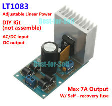
The regulator in your attachment on the other hand is considerably larger, and will handle up to a 7 amp output. It will accept either AC or DC input as well, but does not have DCS interference protection. It would be good for a large trackside accessory supply IMO, if that is what you are needing? I have not used it, so I really can't comment further on it's attributes.

Rod

Getting a bit off-topic, but I was hoping to use it to convert our track ~16-19V AC to a constant 18VDC, to feed a radio-control receiver that was originally designed for on-board battery operation.  The manufacturer of the receiver warned me that it was designed for a battery source, and very picky about not being subject to voltage fluctuations.

So I purchased some of these modules from the auction I mentioned.  They're quite small, maybe 2" x 1" x 1"-- definitely small enough to fit in a loco tender, even with the R/C receiver board in there too.  I didn't think much about heat dissipation.  But if I heat-sink it to the frame hopefully it will be ok.  It just occurred to me that being so close to the receiver, I wonder if it will create radio frequency interference?  Haven't had a chance to try the experiment, too busy with other hobbies and holiday preparations.

Ted S posted:

Getting a bit off-topic, but I was hoping to use it to convert our track ~16-19V AC to a constant 18VDC, to feed a radio-control receiver that was originally designed for on-board battery operation.  The manufacturer of the receiver warned me that it was designed for a battery source, and very picky about not being subject to voltage fluctuations.

So I purchased some of these modules from the auction I mentioned.  They're quite small, maybe 2" x 1" x 1"-- definitely small enough to fit in a loco tender, even with the R/C receiver board in there too.  I didn't think much about heat dissipation.  But if I heat-sink it to the frame hopefully it will be ok.  It just occurred to me that being so close to the receiver, I wonder if it will create radio frequency interference?  Haven't had a chance to try the experiment, too busy with other hobbies and holiday preparations.

Well, a linear supply won't be likely to produce RF issues.  First off, what is the actual current requirement for this RC receiver?  I can't imagine it's in the amps range, so a much smaller supply would likely do the trick.  How about starting a new thread with your issue and some details and we'll see if we can help you?

Circling back to my question about using Rod's device (nee GRJ + AC to DC) for powering LED retrofits for my passenger cars, along with Pete's  idea about wiring up the LED strips in parallel, I think there's a way to avoid having to use a buck-boost circuit for variable AC, to wit:

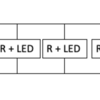
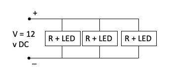
Scrapping the rust off my ability to use Kirchoff's law (this could be embarrassing) - here's my analysis, using some quick sketches in Powerpoint (I don't have anything handy to use actual symbols).  Here's what the 2" long portion of the LED strip light looks like, a parallel circuit with identical resistors (R) to control the current for the LEDs.  The current in just one R + LED leg is I = V/R.  With three legs, Rtotal is R/3 (1/Rtotal = 3/R), so the current in the circuit is now 3V/R = 3 x just one leg (I know, elementary...). :
Screen Shot 2019-12-05 at 5.21.30 PM

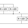
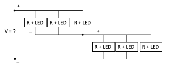
 So using Pete's idea, here what two of these strips look like in parallel:
Screen Shot 2019-12-05 at 5.21.39 PM

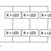
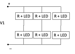
Since all of the R + LED units are the same (or close enough), I claim that the equivalent circuit is:
Screen Shot 2019-12-05 at 5.21.50 PM

so (here's where the rust may show) for each leg, Rleg = 2R and 1/Rtotal = 3/Rleg = 3/(2R) and Rtotal = 2R/3.  Since Rod's device is constant current, V1 = IRtotal = I x 2R/3 = 2/3 x V (original).  So in the original circuit, V was 12 v, so V1 is now 8 v. 

Assuming I've done this right, if each of the LED strips is now 4 inches long (total of 8, which is a little bit shorter than the length of a Flyer passenger car), its:
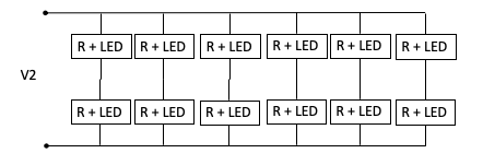
Screen Shot 2019-12-05 at 5.49.33 PM

Using the same analysis as above, I get V2 = 1/3 x V (original) or 4 volts.  Since most of the Flyer AC transformers start around 4 to 5 volts, I should be able to use Rod's constant current/ buck circuit, right??

thanks for any advice ...

- Rich


Attachments

Images (4)
  • Screen Shot 2019-12-05 at 5.21.30 PM
  • Screen Shot 2019-12-05 at 5.21.39 PM
  • Screen Shot 2019-12-05 at 5.21.50 PM
  • Screen Shot 2019-12-05 at 5.49.33 PM

Rust notwithstanding, why not simply hook it up and try it out? And just to be clear the constant current board is the subject of another thread here, and is the creation of grj, not me. The only thing I can take credit for is conveyancing the build documents from their original lengthy thread to the new one! 

Rod

Last edited by Rod Stewart

Add Reply

Post

OGR Publishing, Inc., 1310 Eastside Centre Ct, Suite 6, Mountain Home, AR 72653
800-980-OGRR (6477)
www.ogaugerr.com

×
×
×
×
Link copied to your clipboard.
×
×