
Hi all,

It has been a few years since I posted on here and last time I mentioned about working on a circuit to perform grade crossing flashing on old Lionel 154s, or similar incandescent bulb crossings.

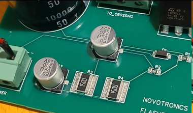
I'm happy to announce recently I've gone back to this and have finished it and replicated it multiple times and have actually made prototype boards. The theory makes sense and it's fairly robust from testing I've performed.

The idea is to have 5 wires coming from the module: 2 for AC in, 1 for GND on bulb terminal, and 2 for bulb terminals. Once AC is supplied the bulbs with flash at a 1 second period and 50% duty cycle.

Video https://youtu.be/VThu2PFCFQs

Now that being said, I am going to do a couple things on this thread:

1. Provide the BOM of the circuit and schematic so you can build it yourself. I can provide support to help you debug or build it via direct message or email if you'd like.

2. Start an eBay store (eventually) to sell these boards for you to plug and play. I was thinking about $20, but I want to understand an interest for it first and see if that seems reasonable for those who do not want to build it themselves.


That being said, I would be curious if the community is interested in this as a whole to be sold. If not, no big deal, would be happy to provide support for the ones who want to build it. Or I could even provide a kit to build it for a cost as well with instructions. Let me know if this is of interest!


Thanks,


James

Original Post

Replies sorted oldest to newest

@GregR posted:

Is this similar to Lionel's part No. 610-2760-300 PCB which was  installed into the base of the No. 6-12760 highway flasher?  I purchased a few of these and wired them in directly below my 154's.

Greg,

This is functionally the same.  Lionel chose to take a different route on design and it allows the mounting underneath to be possible.

You would probably need to wire mine under the layout, but functionally, they do the same thing.

Ok, I'm really cheap. Here's what I cobbled together under my layout. I have 14VAC coming out of my 153IR. One set of leads goes to the 610-2760-300 PCB which is taped to the underside of my layout. From there, wire go straight to the 154. That gives me my flashing lights.

Next is sound. Tapping into the same 14VAC coming from the 153IR, I convert it down to something like 5VDC and feed it into a cheap made-in-China sound recording card (pictured below). About $3 with free shipping on Ebay. I recorded a real grade crossing sound onto the board and set it in "loop" mode. I taped it to the underside of the layout too. Finally, I connected in a speaker that I salvaged from some old toy. There's my sound.

Results in video below.


s-l1600

Attachments

Images (1)
  • s-l1600
Videos (1)
IMG_8659
@GregR posted:


... a cheap made-in-China sound recording card (pictured below). About $3 with free shipping on Ebay. I recorded a real grade crossing sound onto the board and set it in "loop" mode. I taped it to the underside of the layout too. Finally, I connected in a speaker that I salvaged from some old toy. There's my sound.

...

Untitled

Wow, and that free shipping is apparently from a US seller which probably means you don't have to wait weeks!

BTW, it wasn't clear in your video but when you put it in the "Loop" mode is the looping seamless?  Or do you hear a slight gap or hiccup or whatever when it starts again?  And did you have to experiment making several recordings to get the looping "just right"?

Attachments

Images (1)
  • Untitled
Last edited by stan2004

GregR,  I had a hard time hearing the sound and wondered if it was actually much louder to get over the sound of a passing train?  As caveat, I am partially deaf especially at higher frequencies so please excuse if everyone with "20/20" ears hears it perfectly.

As aside somewhat off topic but related, many years ago I had a chance to buy five sound boards and built a unit with four Noma station announcements plus a Marx one (Marx's was interesting sounding...).  I could switch between any one and a button press played that announcement once.  I bring it out when there is an open house and place speaker below the MTH station.   BTW, my favorite Noma announcement is Pennsylvania (maybe because I grew up in Pittsburgh?), played it to death, and can still recite announcement verbatim (and still have station with original mechanism to boot.)

@stan2004 posted:

Untitled

Wow, and that free shipping is apparently from a US seller which probably means you don't have to wait weeks!

BTW, it wasn't clear in your video but when you put it in the "Loop" mode is the looping seamless?  Or do you hear a slight gap or hiccup or whatever when it starts again?  And did you have to experiment making several recordings to get the looping "just right"?

After a couple of tries, my recording was pretty decent. The loop mode does have a slight hiccup every 20 seconds, but it's barely noticable. By 20 seconds, my train has usually passed the crossing anyway.  Yes,  I could clean up the sound file, but it doesn't bother me. I suppose if I were really troubled by lack of realism, I wouldn't have a 154 signal in the first place since it measures a ridiculous 70'-0" tall in O scale.

Last edited by GregR
@rrman posted:

GregR,  I had a hard time hearing the sound and wondered if it was actually much louder to get over the sound of a passing train?  As caveat, I am partially deaf especially at higher frequencies so please excuse if everyone with "20/20" ears hears it perfectly.

As aside somewhat off topic but related, many years ago I had a chance to buy five sound boards and built a unit with four Noma station announcements plus a Marx one (Marx's was interesting sounding...).  I could switch between any one and a button press played that announcement once.  I bring it out when there is an open house and place speaker below the MTH station.   BTW, my favorite Noma announcement is Pennsylvania (maybe because I grew up in Pittsburgh?), played it to death, and can still recite announcement verbatim (and still have station with original mechanism to boot.)

I am sorry you coudn't hear it in my video, but those bells are as loud as ****, even with trains running. Most of the time, I have the connector unplugged because it just gets too annoying.

I found this OGR thread from 2017 where you were entertaining the idea of using an MP3 module for the sound (and possibly even for flashing light timing).  What is your current thinking on sound?  GregR's comment above suggests some kind of volume control (or I suppose basic on/off) might be a nice touch.  If the crossing is active for a few seconds, then no big deal.  But listening to minutes of clanging if the train is stopped on the crossing would drive anyone batty!

To that end, if you are still considering the MP3 route, instead of a volume control perhaps something as simple as a minutes-long bell sound that starts out loud for 20 seconds or whatever and then slowly fades to a background level.  Then back to full volume on the next activation.

I actually thought about suggesting doing it with a PIC and a couple of FET's, but decided against it.

More practically, it could be done with a 555 timer, one resistor and one capacitor, plus the bridge and cap in the power supply. So you could get rid of one capacitor entirely, replace one 1000 uF with a small 10uf or so, and eliminate one resistor.  The output of the 555 is rated 200 mA, just like the 2N3904. The 16V rating of the 555 should not be an issue seeing that we are dealing with 14 volt bulbs anyway. So the flasher proper would go from 6 parts to 3, and smaller parts at that.

Just moving the design from 1968 to 1973.....

Last edited by PLCProf
@PLCProf posted:

More practically, it could be done with a 555 timer, one resistor and one capacitor, plus the bridge and cap in the power supply. So you could get rid of one capacitor entirely, replace one 1000 uF with a small 10uf or so, and eliminate one resistor.  The output of the 555 is rated 200 mA, just like the 2N3904. The 16V rating of the 555 should not be an issue seeing that we are dealing with 14 volt bulbs anyway. So the flasher proper would go from 6 parts to 3, and smaller parts at that.

Just moving the design from 1968 to 1973.....

Sure, but it wouldn't be nearly as much fun.   Besides, with the FET outputs, I could handle amps.

@PLCProf posted:

...

The output of the 555 is rated 200 mA, just like the 2N3904. The 16V rating of the 555 should not be an issue seeing that we are dealing with 14 volt bulbs anyway.

If the 555 output is directly driving the two bulbs, it has a quirky characteristic of providing more power in one half of the cycle.  In other words, given two identical bulbs one might be brighter than the other.  The analysis is somewhat tedious (depends on voltage, bulb power, etc.).  Whether anyone cares or not is open for discussion but this is a known behavior and often rules out the use of the 555 when driving a pair of identical alternating loads.  If the 555 is simply used for timing and the 555 output drives a pair of identical transistors (FETs), then bulbs behave symmetrically.

The issue of the 16V rating is not whether or not the load is a 14V bulb.  It's that in O-gauge the typically accessory voltage is 14V AC.  Put this thru a bridge rectifier and you suddenly have a DC voltage that will smoke a 555.  Plus, many guys use, say, a CW80 for accessory voltage.  These "chopped sinewave" transformers may be set to "only" 10V or 12V AC but the actual DC voltages after a bridge rectifier will also smoke a 555.

Your mileage may vary.

Led flasher = 610-2888-310.

bulb flasher= 610-2760-300

@Chuck Sartor, may I also ask if you have the wiring connections for the LED board 610-2888-310?

IMG_4271

This board comes with a red & black wire soldered to 3RD1 and GND, respectively. I assume the red wire gets connected to the center rail or a fixed voltage terminal, and the black wire is connected to an insulated outer rail or contactor switch. The LEDs I believe are L1 and L2, but does the common LED connection go to the GND solder connection? And what is the purpose of the unused terminal 3RD?

Secondly, I also am assuming that no current limiting resistor needs to be added to each LED? It appears they already exist in the two surface mount resistors labeled 112, or 1.1kohms. Is this correct?

I know it wasn't very expensive, but I still hate to screw up a brand new pcb Thanks!

Attachments

Images (1)
  • IMG_4271

A bit of an update for those still interested.

I made a video about this circuit which includes a schematic and BOM for those who want to give it a go themselves.  It's cheap and has been working very reliably for me the past year.

Here is the video:


Circuit schematic is at 9:40

and circuit BOM is at 13:08


I actually also added sound from an MP3 module and was able to use a cheap Rectifier/Regulator combo to run it.  Wiring this in with the flashing circuit gives it the ability to operate with it.

Let me know if there are any questions and good luck!

I tried to see if it would be viable for me to make and sell these myself, but with costs and what people are willing to spend for this, I am not sure this design is worth it.

Maybe that will be a future project for me, along with making the footprint smaller. 

But for now, this is it!

Last edited by Datdupa46_Novotronics

A bit of an update for those still interested.

I made a video about this circuit which includes a schematic and BOM for those who want to give it a go themselves.  It's cheap and has been working very reliably for me the past year.

Any chance of just posting the BOM and schematic so you don't have to extract it from a video?

@stan2004 posted:

For the avid DIY'er see the OGR Electrical Reference thread with the repository of various and eclectic circuits including printed-wire circuit boards which will vastly simplify the soldering task, schematics, and BOM's.  Project #5 and #6 by @Rod Stewart are alternating flasher projects, one for LEDs, one for incandescent bulbs.

Stan,

Thank you for sharing this!

This is fantastic.

I'm not sure I can follow that complex diagram, can you explain it?

Just kidding...

Thanks for posting, I was curious and hadn't seen the diagram before.

Here's one that's been around forever, uses bigger components but about the same idea.

John,

Haha, very funny

As for the circuit you posted, yes, this is an Astable Multivibrator design just like mine.  Although it is full-wave rectified, while mine is only half-wave rectified.  The 2N3904 also has different characteristics than the TIP3055 for switching.  But they both accomplish the same task with the same theory.

Again, sorry for the blasting tone. I said what I said because of this:  "I shrunk the board down and got rid of the giant cap" doesn't address other major shortcomings from a design perspective.

Again, sorry, we all start somewhere, mistakes are made. Easy enough letting a board patterning software make decisions for you. That said, between just ridiculously over sized components (TO-3P, massive 5.08mm screw terminals, massive SMD resistors) and then the smallest possible traces connecting them, this is near textbook how not to make a PCB and definitely not one to sell.

By all means post a preview of your new design that is smaller, but what I trying to advise you of is this board- to anyone who knows anything about electronics casts doubts on your skills for designing a product worth selling. Understanding component design, sizing, thermal calculations are all part of designing a proper board. Understanding thermal stress just from soldering, good through hole pad guidelines, trace width and size, these are required to making something that can stand up in the field.

Again, I'm sorry, I know you mean well and it's fun to make something and when it works you are very happy. There is plenty of room in this hobby for folks to create electronic boards that perform model railroading functions. I wish you best of luck and again, suggest you post some layout designs of your new board so others can help guide you on a much more robust PCB design that is much more viable for a product.

@Vernon Barry,

With all due respect, thank you for raining on his parade.  While I agree wholeheartedly with your technical analysis, and thank you for it, your comments are near textbook on how to discourage people not to pursue their dreams.

This forum is not generally about critiquing electronic designs, although we do it from time to time.  It's about coaching and encouraging success within our core hobby, which is fortunately not electronics.

Mike

Last edited by Mellow Hudson Mike

Again, sorry for the blasting tone. I said what I said because of this:  "I shrunk the board down and got rid of the giant cap" doesn't address other major shortcomings from a design perspective.

Again, sorry, we all start somewhere, mistakes are made. Easy enough letting a board patterning software make decisions for you. That said, between just ridiculously over sized components (TO-3P, massive 5.08mm screw terminals, massive SMD resistors) and then the smallest possible traces connecting them, this is near textbook how not to make a PCB and definitely not one to sell.

By all means post a preview of your new design that is smaller, but what I trying to advise you of is this board- to anyone who knows anything about electronics casts doubts on your skills for designing a product worth selling. Understanding component design, sizing, thermal calculations are all part of designing a proper board. Understanding thermal stress just from soldering, good through hole pad guidelines, trace width and size, these are required to making something that can stand up in the field.

Again, I'm sorry, I know you mean well and it's fun to make something and when it works you are very happy. There is plenty of room in this hobby for folks to create electronic boards that perform model railroading functions. I wish you best of luck and again, suggest you post some layout designs of your new board so others can help guide you on a much more robust PCB design that is much more viable for a product.

Hi Vernon,

First off I want to say:  I am not planning on selling these whatsoever.  As you pointed out about some aspects about the board layout: this board simply put, is a far way from sale material.  I have just been using them for my personal train layout for the past year or so and it seems like that is where they will live!  Never say never, but I doubt I will ever be selling any boards.  There's a number of reasons for this, I think the biggest is that I am not too happy with the trade-offs of this circuit design in general, even before getting down to the board level.  I have been re-thinking ways to produce the waveforms necessary for this with the correct input requirements and I have a few new circuits that can do it.  Also, I won't have the bandwidth to do much customer service which I believe is necessary to sell a product like this.  No need to be sorry either, in fact I did say "judge away" when it came to this design, because it was my first time ever laying out a board like this.

I have no issues with your response at all!  It's passion.  I appreciate the constructive criticism and I would really appreciate some help and guidance if you would be willing to provide some more detailed advice!  I can provide all the design files you need.  I do have some more detailed and direct questions about some of the things you mentioned.  Based on your response, it sounds like you have professional electrical engineering experience with products shipped under your belt, so it will be nice to talk some shop

I think it may be best to take it to another venue though, as Mike mentioned this isn't the typical spot for this type of thing.  Let me know if this is something you are interested in.  I would appreciate the guidance.

I had not seen this thread before, but @gunrunnerjohn's transistor circuit, evoked vivid nostalgic memories for me. It's called an astable multivibrator and was one of the first transistor projects I built in the late 1950's. (I may have also given away @gunrunnerjohn's age ) I may have seen the design in a Popular Electronics back then.

The astable multivibrator was first invented during WW1 by two French professors Henri Abraham and Eugene Bloch using the just-invented triode vacuum tube. Its application was to help precisely measure radio frequencies and used by the French, English and U.S. military.  They both continued to make other advancements radio wave engineering in later years.

The Gestapo arrested Abraham in 1943 and Bloch in 1944. Both were murdered in the Auschwitz Concentration Camp.

@Bruce Brown posted:

I had not seen this thread before, but @gunrunnerjohn's transistor circuit, evoked vivid nostalgic memories for me. It's called an astable multivibrator and was one of the first transistor projects I built in the late 1950's. (I may have also given away @gunrunnerjohn's age ) I may have seen the design in a Popular Electronics back then.

The astable multivibrator was first invented during WW1 by two French professors Henri Abraham and Eugene Bloch using the just-invented triode vacuum tube. Its application was to help precisely measure radio frequencies and used by the French, English and U.S. military.  They both continued to make other advancements radio wave engineering in later years.

The Gestapo arrested Abraham in 1943 and Bloch in 1944. Both were murdered in the Auschwitz Concentration Camp.

Bruce,

Thanks for the History lesson! Very fascinating. Sad ending, unfortunately.

As for the theory, I took an IC design class in college and I remember learning about this! That's where I pulled this from when I came up with the design.  This theory is very elegant.  Abraham and Bloch did tremendous work.  I have an electronics textbook that outlined this and it made the most sense. There's also the mono-stable (one stable state) and bi-stable (two stable states) multivibrators. They are used all over today. The astable multivibrator means there is no stable state, so it oscillates. I remember learning how to design clock generators and oscillators with this theory in mind.

The simplicity of this design is its greatest asset

Thanks for the trip down memory lane back to EE school!

Last edited by Datdupa46_Novotronics

Add Reply

Post

OGR Publishing, Inc., 1310 Eastside Centre Ct, Suite 6, Mountain Home, AR 72653
800-980-OGRR (6477)
www.ogaugerr.com

×
×
×
×
Link copied to your clipboard.
×
×