Yeeco 0-199.9VAC meter...is there a calibration pot inside?
John, Presumably my old RW and LW transformers put out a pure sine wave? So a cheap meter has a better chance of being more accurate?
Dennis, Did you compare the Yeeco meter with your Fluke at lower voltages?
No, I did not compare at low voltages. As low as maybe 15 to 18 was the range. I can do more tests, but I'm sure it's not super accurate like my Fluke, and I didn't read a 'True RMS' claim which the Fluke does make.
Dennis
Yep, the PW transformers will probably work just fine with the cheap panel meters. Once I tweaked the calibration pot on the one I tested, it indicated pretty accurately on the old PW 1033 over the full range. It was only when I got to the Z-1000 with the Z-Controller that the wheels fell off. ![]()
Dennis, mine was WAY off at lower voltages, that's why I asked. I'm afraid I expect a little more accuracy than 33% of the actual voltage! ![]()

Attachments
I agree, that's dismal. However, since my meter is very close to my Fluke at the voltages I'm using, I'm satisfied. It does the job. But now I'm curious, and will test it at lower voltages. Is yours off that much at 18VAC?
Dennis
Did you read my post on the tests?
After tweaking the Yeeco, it tracks my 30 year-old Fluke 77 well. But the Yeeco is now farther from the Fluke 115, which agrees with neither meter. Still, that the Yeeco agrees with the averaging Fluke 77 is good enough for me. I'd expect the 115 to read higher since it's true RMS. There may be differences in Yeeco samples, and I got a good one.
Dennis
Attachments
Not sure why you are happy with being off 20%. The Yeeco and the Fluke 77 are both deficient in reading accurately for "sharks tooth" variable voltage sources. Even Fluke can make a sine wave only voltmeter that should only be used for measuring sine wave sources.
If anything, I would make a table of say 5 vac to 18 vac with the Fluke 115 true rms meter as the standard while measuring a shark's tooth output voltage and adjust the Yeeco to best approximate it's readings. That should be quite telling and as good as you are going to get. You could even make a correction table and glue it to the Yeeco. Like say 12 vac on the Yeeco requires to add 3 vac, etc.
Yes, like I had explained earlier, I know what the difference is, so the meter works for my purposes. I'm not using it for anything else but monitoring track voltage changes/trends. A true RMS meter dedicated to my fastrack just doesn't make $sense$ to me, but everyone has their own opinion.
Thanks,
Dennis
J Dennis posted:...I know what the difference is, so the meter works for my purposes. I'm not using it for anything else but monitoring track voltage changes/trends. A true RMS meter dedicated to my fastrack just doesn't make $sense$ to me, but everyone has their own opinion.
This hits the nail on the head. I don't think the averaging vs. RMS measurement issue will ever be laid to rest. Even if there were such a low-cost, true-RMS, combo panel meter for O-gauge AC ranges, there will be threads like clockwork about why my analog needle meter, or why my Harbor Freight meter, or why my fill-in-the-blank meter reads such and such.
Here's a plot of GRJ's results on the Z-1000:
Ideally the subject meter readings would fall on the 1:1 black line. I suppose one could print up a correction table but note that the error in percentage comes from how far the measured signal varies from a sinewave. The rub is that for triac-based chopped sinewave controllers like the Z-1000 or CW-80, the error increases as the voltage is reduced since, in effect, the original transformer sinewave is chopped that much more to create the lower voltages. A potential issue is not all chopped sinewave controllers slice up the waveform in the same way. For example, the DCS TIU variable channels use a pair of FETs (transistors) rather than a triac to do the chopping. This method provides a bit more flexibility in how/where the sinewave is chopped so it might need its own correction table. Maybe no big deal but a consideration nonetheless.
Attachments
Yes, I noted that 'error' on my cheap, Chinese scope. As the TPC-300 voltage approaches max, the wave looks more like my LW's output. At very low voltages, the display jumps 0 to V max (shark tooth) but only the peaks+/- are displayed. Increase voltage, and the wave 'fills out.' As long as I know the difference 'tween VAC RMS vs the Yeeco's averaging VAC, I'm satisfied.
BTW, nice graph.
Thanks,
Dennis
J Dennis posted:I agree, that's dismal. However, since my meter is very close to my Fluke at the voltages I'm using, I'm satisfied. It does the job. But now I'm curious, and will test it at lower voltages. Is yours off that much at 18VAC?
Dennis
If the meters are made in China or the far far East, maybe they use a different kind of electricity/design/measurement etc which is why so much of that stuff is still basic junk class? I have a couple of older meters that were made in Japan and they seem to be more accurate. Same with some old dial ones made in USA, I think. Now it's got me to wondering where I saw them last.
Electricity behaves the same way in China as it does in the US. ![]() China uses 220V 50HZ power, Japan uses 100V 50hz or 60hz power, depending on what part of the country.
China uses 220V 50HZ power, Japan uses 100V 50hz or 60hz power, depending on what part of the country.
While looking for something else, I found this a couple days ago. IIRC, it compares the voltage readings from my voltage car (a copy of GRJ's that he helped me with) with a TRMS meter and one of the 'free' Harbor Freight meters. The voltage car has very similar AC voltage meters to the ones being discussed here. They are from ebay a few years ago and are 0-200vac range (may be 0-199.9, I forget?).
I can't remember exactly what I was powering the track with, but I was thinking it was one of the TIU variable channels powered by a PH-180 brick. If not it was a Z-1000 with Z controller, the only other chopped sine wave device I have. Either way the voltage output was chopped.
FWIW anyway, here are the readings. The Extech EX205T is a TRMS meter, the voltage car and Harbor Freight meters are not TRMS meters.
| Voltage Car | Extech EX205T | Difference | Harbor Freight | Difference | ||||
| 2.3 | - | 5.3 | - | 3 | - | 2.5 | - | 0.2 |
| 4 | - | 7.98 | - | 3.98 | - | 4.2 | - | 0.2 |
| 5 | - | 9.31 | - | 4.31 | - | 5.2 | - | 0.2 |
| 6 | - | 10.51 | - | 4.51 | - | 6.3 | - | 0.3 |
| 7 | - | 11.78 | - | 4.78 | - | 7.3 | - | 0.3 |
| 8 | - | 12.79 | - | 4.79 | - | 8.3 | - | 0.3 |
| 9 | - | 13.73 | - | 4.73 | - | 9.4 | - | 0.4 |
| 10 | - | 14.62 | - | 4.62 | - | 10.4 | - | 0.4 |
| 11 | - | 15.42 | - | 4.42 | - | 11.4 | - | 0.4 |
| 12.1 | - | 16.41 | - | 4.41 | - | 12.5 | - | 0.4 |
| 13 | - | 17.12 | - | 4.12 | - | 13.4 | - | 0.4 |
| 14 | - | 17.75 | - | 3.75 | - | 14.5 | - | 0.5 |
| 15 | - | 18.25 | - | 3.25 | - | 15.5 | - | 0.5 |
| 16 | - | 18.98 | - | 2.98 | - | 16.4 | - | 0.4 |
| 17 | - | 19.29 | - | 2.29 | - | 17.4 | - | 0.4 |
| 18 | - | 19.87 | - | 1.87 | - | 18.4 | - | 0.4 |
| 18.5 | - | 19.9 | - | 1.3 | - | - | - | - |
| 18.6 | - | - | - | - | - | 18.6 | - | 0.1 |
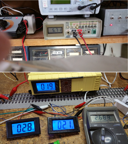
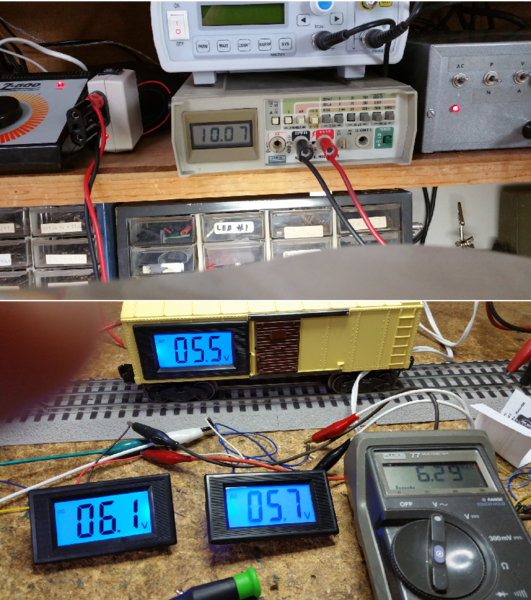
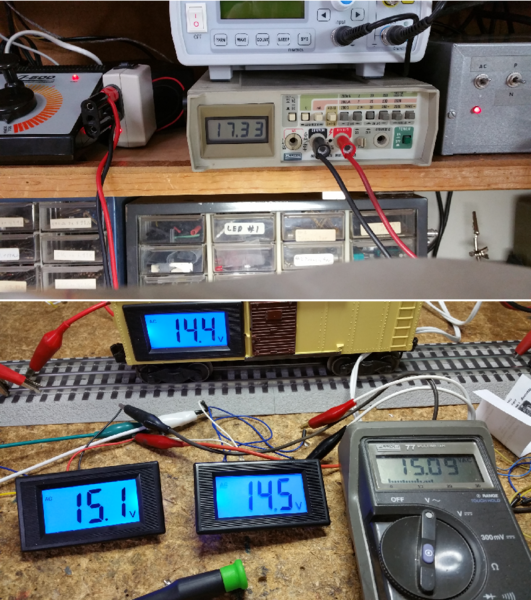
Here's my final test. I took three meters from different purchases, but all AC meters with separate supplies. All of the meters were powered individual from isolated supplies, they got a bit "wonky" if I tried to power them from a common supply, even though it was isolated from the measured voltage. Don't know what that was all about, but I just adjusted and moved on.
The top display is a Fluke TrueRMS bench meter, and it is reading very close to the real voltage from the Z-1000 transformer I use on my bench. The bottom three are my voltage measuring car, and two other meters that were purchased at different times. The other meter is a 20 year old Fluke that is not a true-RMS meter, note it gets a pretty similar reading as all the cheap meters.
I think the chances of buying one of these cheap Chinese meters that will accurately measure a chopped waveform is pretty close to zero.
It's interesting to note that the latest purchase had a calibration pot, and I had calibrated it to read properly from a pure sine wave transformer, the 1033. It tracks the older Fluke pretty well, so I suspect it's accurate withing the confines of using a pure sine wave on the tracks.
Attachments
My Yeeco wasn't advertised as RMS and doesn't function as RMS. It reads about the same as all my other digital and analog non-RMS meters, similar to John's. I used a RMS meter to adjust the Yeeco to the operating voltage I use (17 - 18), and it's accurate within that narrow range, the only range I care about. For the little $ and intended use, I'm pleased.
Dennis
Thanks John, for your time and trouble. My opinion, the volt meters have been put to bed. Within 18-20% accuracy of RMS, cheap, 5-10$, is the best you'll get on voltage. Make your own decision. Has anybody bought the ammeters? Would it make sense that the accuracy would be in the same range? TW
Edit: What's anybodys best guess on why you can't power two(or more) of these meters from the same independent power source?
I have an AC ammeter coming, my guess is it'll have the same kind of issue. Watch this space, I'll post the results of any tests. ![]()
The current/ammeter issue will be similar but is a slightly different kettle of fish.
Virtually all measurements will be of a "chopped" current. Unless you are driving only resistive loads such as incandescent passenger car bulbs, ALL command electronics have bridge rectifiers to convert the AC to DC. So even if the voltage is be pure-sine, the current will be "chopped" though in a slightly different manner than voltage chopping. I can't recall if GRJ has posted current waveform examples but in basic terms no current in drawn when the voltage is near 0 or a few volts. Then you get a spike or pulse of current near the peaks of the voltage.
So averaging analog meters or averaging digital meters (like their voltmeter counterparts) will under-report the "chopped" current drawn by modern engines (with bridge rectifiers).
What I predict will be the conundrum is the current range of interest is, say, 0-10 Amps (wide) where as the voltage range of interest is, say, 14-18V (narrow) and pure-sine for command applications. Attempts to mess with the calibration adjustment on the inexpensive averaging meters may be unsatisfactory if trying to measure over a wide range. Note that this has nothing to do with whether the current/ammeter uses the donut-style current-transformer or a built-in shunt to sense the current.
I'm certainly expecting similar operation from the ammeter, no real reason to expect anything else.
The fact that multiple meters can't be powered from the same isolated source, is cumbersome at best. Six or eight power supplies to run the meters. What's that about?
TedW posted:The fact that multiple meters can't be powered from the same isolated source, is cumbersome at best. Six or eight power supplies to run the meters. What's that about?
These...
https://tonystrains.com/rrampm...-by-dcc-specialties/
are starting not to look that expensive...
TedW posted:The fact that multiple meters can't be powered from the same isolated source, is cumbersome at best. Six or eight power supplies to run the meters. What's that about?
I didn't actually go back and revisit that, but I think it was just the one type of meter that had some issue. The two meters in my voltage measuring car are powered from one power supply, and it's no problem there. I don't know why the one meter did something odd powered in parallel with the other, but I didn't want to chase that at the time.
cjack posted:TedW posted:The fact that multiple meters can't be powered from the same isolated source, is cumbersome at best. Six or eight power supplies to run the meters. What's that about?
These...
https://tonystrains.com/rrampm...-by-dcc-specialties/
are starting not to look that expensive...
I'm still having a bit of sticker shock at the model that will measure the full voltage range. ![]()

Attachments
The reason I ask is that these two are hooked to the same independent source, but as soon as I hooked the amp meter inline to the bulb load, it went dim(out) and never worked again. The obvious reason would be I hooked ammeter up wrong, but I'll tell you; "I did not have sexual relations with that woman..." So what next?
Attachments
The ammeter needing a separate supply might make more sense than the two voltmeters measuring the same thing. I'm thinking maybe the way the AC was connected to them might have had an effect, I can't say. I've never had one of these ammeters, so I don't know if they require a totally isolated supply, but that may be a factor.
Think of the 9V battery in a typical DMM. It's an isolated power source. Then think if you could jumper 2 wires from that single battery to a power a 2nd DMM (or 3rd, 4th, etc.) and expect both (all) meters to work.
Each meter needs an isolated source because this allows the metering electronics to "float" to the potential of the measured voltage; it needs to establish a local 0 or common to make a reference for measurement purposes.
If I understand the two examples, in the first the two meters measured the same voltage; in the 2nd the two meters measured the voltage and current of a single circuit. I assume the ammeter was not of the donut type?
Seems to me in both cases you've created a circuit in a literal sense where current can flow from the measured device into one meter, to the common power source, thru the other meter, and finally back to the measured device. This additional circuit breaks what should be a monogamous relationship between a meter and what it is measuring.
With an identical power connection and measured voltage connection, I would expect the same design meter to work. As I said, if the two measured voltage connections were crossed, it would be an issue. Since meters with different types of connections were used, there was no easy way to determine if they were the same design and the same "polarity" of the measured connection.
It's probably best to assume these meters require individual isolated power sources.
GRJ, I think I may have the same meters as you do in my voltage car. They too work off just one power supply, just as yours do in your car, FWIW.
TedW, I had a couple of these meters go dark as well! ![]() Fortunately they are pretty inexpensive, and then GRJ helped me out with the isolated DC to DC converters. That was a few years ago and all has been well since.
Fortunately they are pretty inexpensive, and then GRJ helped me out with the isolated DC to DC converters. That was a few years ago and all has been well since. ![]()
cjack posted:TedW posted:The fact that multiple meters can't be powered from the same isolated source, is cumbersome at best. Six or eight power supplies to run the meters. What's that about?
These...
https://tonystrains.com/rrampm...-by-dcc-specialties/
are starting not to look that expensive...
I am starting to think the same thing... Wonder if we could get by with a I (or a II if case is needed)? They are rated for 10 amps. The II is getting up close to the 'Super Deluxe' IV model though.
Tony's has a pretty knowledgeable staff, maybe I will give them a call if I get more serious about these things. I really do like the dual volt/amp meter idea and they are digital as well.
rtr12 posted:TedW, I had a couple of these meters go dark as well!

I think I'm forgetting the ammeters. Re-think if GRJ comes up with something worthwhile. Because I don't huddle up behind my transformer, I can't see the analog gauges on it, so I use the digital volt meter for a quick reference when I hit the switch on the power supply. If it goes to the same number, all's good. Accuracy, nope, but the same each time. That'll have to do till something better is available and affordable.
Attachments
I currently have separate analog meters (volt and amp) on all my track loops. Also as you say, good enough for me for now. I would prefer digital combo meters, but have never been able to find any. I use bricks (PH-180s) for power so the analog meters are all I have other than a few various multi-meters (not permanently connected), some TRMS and some not.
(Tony's are looking better all the time, can't take it with you when you go! ![]() )
)
Do NOT try this at home. ![]()
Here's a DIY modification to the combo Voltmeter-Ammeter module willygee introduced to us at the beginning of this thread - less than $10 on eBay.
As discussed earlier, I suggested there are 3 modifications required to make this self-powered combo meter better suited for O-gauge AC transformer monitoring.
Task 1. Reduce the operating voltage range so it runs at typical AC Accessory/Command voltages...or, say, 12V-20V AC rather than the 60-80V AC specified in the stock version.
Task 2. Increase the resolution 10x so that it read Voltages with 0.1V resolution (rather than 1V for the stock version)
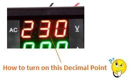
Task 3. Add the decimal point to the LED display to indicate the Voltage is indicating 0.1V resolution
I made these modifications. First the proof of life video:
This is a very tedious modification and I don't wish it on anyone. But since I did it, I minds as well show what I did. This is just my 2 cents - no warranty, no refunds!
Task 1. The module indeed uses the "red capacitor" to drop the AC voltage. The stock unit has a 0.47uF/400V capacitor. I placed a 2.2uF/50V in parallel to reduce the capacitor's voltage drop at 60 Hz so that it can operate at O-gauge transformer voltages.
Task 2. The module has 1V resolution. There is a 2M Ohm resistor which is a main voltage dropping/divider resistor for the Voltage measuring function. I added a 100k Ohm resistor in parallel so there is less drop. The same trimmer/calibration trimpot (labeled VR) was used.
Task 3. The most tricky modification is almost cosmetic in that all it does is turn on the decimal point (DP) LED in the Voltage readout. This is not as "simple" as turning on a discrete LED. The LED display in the module is a so-called multiplexed display where timing is everything. You have to turn on the decimal point LED for the center Voltage digit only when the center Voltage digit is active which is essentially 1/6th of the time since there are 6 digits. So a circuit with a PNP transistor, diode, and 2 resistors must be spliced in to the existing circuit. This could have been effected with a line or two of code change in the software for the microcontroller chip but we have no access to this code nor the ability to re-program the chip. The before-after schematic is shown below.
The locations of where to tap/splice into the module are shown in the following 2 before-after photos; these are high-resolution shots so should be click-able to zoom in and see exactly where to mods are made:
All components were from my parts stash but $1-2 if purchased. Unfortunately a LOT of grief and tedium!
And while my interest is/was to monitor command/accessory voltages/currents, I understand some guys might want to measure down to 0V AC. Here's a hint. The dropped AC voltage goes through a bridge rectifier, into a zener diode that limits the DC voltage to about 11V DC, and into a 6203A voltage regulator IC with 4.4V DC output.
Attachments
That's pretty cool Stan!! Amazing to me that you got that all figured out, very nice project. Also thanks for the instructions and pictures just in case I ever want to give it a try. That definitely provides us with a dual volt/amp meter in our model train ranges. Thanks for going to all the effort to make it and posting for us to see.
stan2004 posted:Do NOT try this at home.
Here's a DIY modification to the combo Voltmeter-Ammeter module willygee introduced to us at the beginning of this thread - less than $10 (free shipping) on eBay. As discussed earlier, I suggested there are 3 modifications required to make this self-powered combo meter better suited for O-gauge AC transformer monitoring.
Task 1. Reduce the operating voltage range so it runs at typical AC Accessory/Command voltages...or, say, 12V-20V AC rather than the 60-80V AC specified in the stock version.
Task 2. Increase the resolution 10x so that it read Voltages with 0.1V resolution (rather than 1V for the stock version)
Task 3. Add the decimal point to the LED display to indicate the Voltage is indicating 0.1V resolution
I made these modifications. First the proof of life video:
This is a very tedious modification and I don't wish it on anyone. But since I did it, I minds as well show what I did. This is just my 2 cents - no warranty, no refunds!
Task 1. The module indeed uses the "red capacitor" to drop the AC voltage. The stock unit has a 0.47uF/400V capacitor. I placed a 2.2uF/50V in parallel to reduce the capacitor's voltage drop at 60 Hz so that it can operate at O-gauge transformer voltages.
Task 2. The module has 1V resolution. There is a 2M Ohm resistor which is a main voltage dropping/divider resistor for the Voltage measuring function. I added a 100k Ohm resistor in parallel so there is less drop. The same trimmer/calibration trimpot (labeled VR) was used.
Task 3. The most tricky modification is almost cosmetic in that all it does is turn on the decimal point (DP) LED in the Voltage readout. This is not as "simple" as turning on a discrete LED. The LED display in the module is a so-called multiplexed display where timing is everything. You have to turn on the decimal point LED for the center Voltage digit only when the center Voltage digit is active which is essentially 1/6th of the time since there are 6 digits. So a circuit with a PNP transistor, diode, and 2 resistors must be spliced in to the existing circuit. This could have been effected with a line or two of code change in the software for the microcontroller chip but we have no access to this code nor the ability to re-program the chip. The before-after schematic is shown below.
The locations of where to tap/splice into the module are shown in the following 2 before-after photos; these are high-resolution shots so should be click-able to zoom in and see exactly where to mods are made:
All components were from my parts stash but $1-2 if purchased. Unfortunately a LOT of grief and tedium!
And while my interest is/was to monitor command/accessory voltages/currents, I understand some guys might want to measure down to 0V AC. Here's a hint. The dropped AC voltage goes through a bridge rectifier, into a zener diode that limits the DC voltage to about 11V DC, and into a 6203A voltage regulator IC with 4.4V DC output.
Stan
Thanks for sharing the information. It looks like the modified meter somewhat reads the same as the Z4000 meters. Did you have a chance to compare the V & A reading of the modified meter with a Fluke or something similar. Also, if we want to duplicate what you did, what was the ordering info for the meter you modified.
Thanks,
Bob D
Stan, you certainly went that "extra mile" on this one! ![]() I think I'll just connect a couple of fluke meters to the tracks.
I think I'll just connect a couple of fluke meters to the tracks. ![]()
![]()
Fluke-45 dual-display can show both V and I, and can be had for less than $100. The GDM-82451a was available for $80 and less on eBay earlier this year, casts offs from the ITT school closing. It can also display VAC and I simultaneously.
Dennis
rad400 posted:Thanks for sharing the information. It looks like the modified meter somewhat reads the same as the Z4000 meters. Did you have a chance to compare the V & A reading of the modified meter with a Fluke or something similar. Also, if we want to duplicate what you did, what was the ordering info for the meter you modified.


