I have another layout advice question for the ones more expert than I.  I didn't know if it was best to create new thread or continue my Inglenook Sidings for a Boy Scout Merit Badge question last December

(https://ogrforum.ogaugerr.com/t...ge-inglenook-sidings )as is a totally different question.  If the mods feel that it should be same thread, please feel free to merge them.


Just to recap, I want to do a switching layout 100% based on action accessories (Sawmill, etc.) without any consideration for realistic operations.  Just to have fun and watch all the items hard at work.


My current proposal for my home layout is a 18" x 144" switching layout using two Wye connections on each end.  I plan on designing it using FastTrack, Tubular and RealTrax.  So far, I've just done the FasTrack version (O36 switches).  I plan on having 6-8 action accessories on 4 end sidings (they are roughly 10-11 inches apart) and have used to the Wye connections to create a runaround track.  In the middle of the layout where the runaround track is I'm planning on placing a long and narrow accessory like the Barrel Loader.


Are there any pitfalls that I've not thought of?


Thanks.


Fastrack 18x144 A

Attachments

Images (1)
  • Fastrack 18x144 A
Last edited by Amfleet25124
Original Post

Replies sorted oldest to newest

A single sheet of plywood will give you a 144" x 32" (roughly) switching deck with the two free cuts you get at the home improvement store. I have several designs in this size -- some free-standing, some as modules for a larger planned layout (FreeMo-inspired).


Going with a wider deck gives you more options for your industries, even if you're not going for prototypical appearance.


Originally Posted by L.I.TRAIN:

Kevin

Interesting, one suggestion I have is to consider shortening the distance between the Wye's to add space on the end sidings.


Keep posting as this is certainly unique, would love to see your progress and end state

Steve

That's a thought.  I think that I would need to keep at least one 10-inch straight in the middle of the Wye's (to avoid an S-Curve) and then make on set of spurs longer than the opposing end.  Or are the radii of the Wye's gentle enough to avoid the S-Curve issue when connecting two Wye's together?


Originally Posted by ChiloquinRuss:

to add space on the end sidings or the opposite, shorten the spurs to just fit the loco and one car.  This adds to the puzzle effect especially if the industry is a two car spot.  Russ

I like the puzzle aspect of your idea, as I'm enamored by them, and especially as I'm doing a N-Scale Inglenook for the Boy Scout Railroading Merit Badge class that I'm teaching in March.  Hmmmmm.  


Originally Posted by AGHRMatt:

A single sheet of plywood will give you a 144" x 32" (roughly) switching deck with the two free cuts you get at the home improvement store. I have several designs in this size -- some free-standing, some as modules for a larger planned layout (FreeMo-inspired).


Going with a wider deck gives you more options for your industries, even if you're not going for prototypical appearance.


Matt, the only catch with that is that I'm using the Woodland Scenic's Mod-U-Rail benchwork.  I could push the end maybe 2 inches on the operating panel side.  I want the back to be flush with the wall so that I can have a backdrop.  I'm trying to keep it narrow, so using the 36-inch width Mod-U-Rail for that length is too wide.  You mentioned 32 inches.  What if I went with 24-inch width (using 3 24x48 folding tables as my benchwork)?  That should create enough room.  If I wanted to use both the Lionel Culvert Unloader and Loader, I would need to have at least a 24-inch width so that I could set them up on the track against the back and leaving room for other accessories on the track up front.


Kevin,

I wanted to practice with RRTrack, so I thought I'd recreate your layout.


I used 072 switches (I just like the geometry better) and I left one end longer than the other for the culvert pair. 10" in the center, for perhaps the milk car.


If it were longer, I would put a set of switches in one end for and engine escape. It also, seems like that there should be some uncoupler tracks somewhere.


I don't know this layout design logic well , so I may be off base.


Anyway, it helped me get the practice that I needed. rrt file attached.

Amfleet Swiyching 3D

Attachments

Images (1)
  • Amfleet Swiyching 3D
Files (1)
Last edited by Moonman

You don't need an escape track because it's inherent in your design, assuming your spurs are long enough to hold an engine and at least one car. An engine entering a facing point spur only needs to back up & drop off its car between the switches and then perform a runaround to push the car into the spur.

Thanks for all of your input.


I’ve looked at the options and even with wanting a backdrop along the wall, using the 18-inch wide Mod-U-Rail benchwork really limits my opportunities for some of the accessories.  I’ve decided to go ahead at this time and stretch it to 24/30 inches and by using two 30x72 folding tables as my benchwork (I’m not much into carpentry).  I don’t want to go wider than that.  Even 3 feet is a bit too wide and will dominate the family room (as I'm also building a 1:400 scale model airport on the opposite side from the train layout) especially the triangular real estate area that I have been allotted by the CEO.  The standard folding table along the wall is unassuming.  The tracks will still be 10.5 inches apart but the track area will be 30 inches wide at both end thirds (to place structures) narrowing to 24 inches for the middle 48 inches where the control panel area would be. 


Speaking of dominating, I knew the Culvert Loader and Unloader were both two-dimensional space eaters, but looking at Moonman’s rrt image, they dominate vertically also, maybe a bit too much.  As the most expensive of the shopping list, they are already the last on the list and may stay off the menu.


As I work on this more, and hopefully stick with this plan, I’ll provide updates

Fastrack 30x144


I do need to look into downloading the RRTrack software, so that I can get realistic 3D images rather than my "guestimated" measured shapes 

Attachments

Images (1)
  • Fastrack 30x144
Last edited by Amfleet25124

Kevin,

The 072 wyes need a fitter or makeup piece which is a 1 3/8 half-roadbed. That makes the straights between the 036 switches 47" 4-10" & 4-1 3/4".


Fitting a ZW will be tight. I couldn't find the K-Line acc. and the Moe & Joe. Looks like your estimates for your acc. placeholders are right on.


Edit: Oops, meant to post the 3D-not 2 track plans-fixed now

Attachments

Images (2)
  • Amfleet Switching track plan
  • Amfleet Switching 3D
Last edited by Moonman

Thanks Carl, you didn't have to do that diagram for me, but you did.


What this still tight squeeze shows is that even thought I like them, the Culvert pair probably won't make the final cut.  Because of their huge 3D footprint, placing them on the front rail would hide the back rail rendering it useless and I thus lose out on the placement of potentially 3-4 other accessories.


On the Moe & Joe, the box shown on the plan for it is just the Dump Bin.


Originally Posted by Gilly@N&W:
Originally Posted by AGHRMatt:

A single sheet of plywood will give you a 144" x 32" (roughly) switching deck

And if you can make it 32" wide, you can build a TimeSaver layout.


Gilly


Originally Posted by Ron045:

You have a nice plan and a good goal on how you want to operate.


Have you considered a "timesaver" design?  It might present more challenging fun.

Click here for the operating rules


Timesaver


Yes, I am enamored by the Timesaver.  In fact, my original thought pattern for my Boy Scout Merit Badge Class next month was to have both the Inglenook Sidings and the Timesaver on their own tables (both in N Scale).  Time and other things have caught up with me so I'm only going to do the Inglenook this year.  Maybe add in the Timesaver for 2016.  Looking at both the Timesaver and Inglenook together is actually what made me came up with the design that I have right now.


Off topic - I think that I have finally came up with a name for my railroad and that is the N&O Railroad, or O&N (I haven't decided which one to use yet) as I dabble in both scales.  The railroad will have 3 divisions, the 160 Division (N Scale), the 4350 Division (O Gauge), and the 2531 Division (Halloween/Christmas Layout).


Last edited by Amfleet25124

Update.


I'm sending thanks to two OGR members on two different forum subjects (3-Rail being the other).


Heartfelt thanks to member Moonman who drew up RRT plans for me for both of my switching layouts.  I’ve settled on a 36x144 Inglenook Sidings and have since purchased the RRT software and have had fun playing around with it and made some changes from what Moonman set up for me including using Atlas O track.  Thanks Carl!


Another one of the things that makes the OGR forums and the way members help each other so wonderful.

Last edited by Amfleet25124

Here is my first attempt at trying to insert a RRT File


Inglenook 36 x 144 Atlas O - V1 [5.6.15) Plan View


The American Flyer Terminal Shed in the town area gives the illusion that the tracks go to parts beyond.  The second track by itself is purposely not connected to the rest of the tracks and will have static passenger coaches parked next to an extended platform that goes all the way to the bumper.


Still have some green spaces left up front and I'm deciding if I want them to remain as open spaces or to place some non-operating structure in those locations.


Inglenook 36 x 144 Atlas O - V1 [5.6.15) 3D View 1

Inglenook 36 x 144 Atlas O - V1 [5.6.15) 3D View 2


I'm going to need some help from more experienced users. (1) How does one take correct the roadway showing up on the 3D view in areas its not supposed to be, and (2) I've only been able to design rectangular bases.  I would like if possible to shave off 18" x 18" triangles on each end.  


Any help would be appreciated.

Attachments

Images (3)
  • Inglenook 36 x 144 Atlas O - V1 (5.6.15) Plan View
  • Inglenook 36 x 144 Atlas O - V1 (5.6.15) 3D View 1
  • Inglenook 36 x 144 Atlas O - V1 (5.6.15) 3D View 2
Last edited by Amfleet25124

Thanks for the kind words, Kevin. You are welcome.


When you begin a layout, set only the room size or a workspace lthat is about 2-3 larger than the the layout table. Then open the terrain tab and select a polygon for the table and draw the shape that you need. A few practice attempts will let find where to start and to to observe the oriebtation and length of each side that draw.


I have also encountered unwanted roadway and could not get it to go away. I had to start over. Why don't you email RRT support and send (attach) the plan and then share the fix or proper way to place roadways.

Last edited by Moonman

Here's one I think would work well as both a practical switching puzzle and part of a larger layout. One of the keys to the operation is that the industries compliment each other. This is citrus industry based with an icing facility, a box factory, and a packing house. Packing houses were frequently near depots so I have a Walthers depot standing in for a Santa Fe depot kit I plan to use. It's 12' long and 32" wide, but could easily sit on top of 24" tables.


12.0x2.8_Packing_House_District-Single_Track--3-rail-No4_Turnouts_with Box Shook Factory 3d

12.0x2.8_Packing_House_District-Single_Track--3-rail-No4_Turnouts_with Box Shook Factory

Attachments

Images (2)
  • 12.0x2.8_Packing_House_District-Single_Track--3-rail-No4_Turnouts_with Box Shook Factory 3d
  • 12.0x2.8_Packing_House_District-Single_Track--3-rail-No4_Turnouts_with Box Shook Factory
Originally Posted by Moonman:

Thanks for the kind words, Kevin. You are welcome.


When you begin a layout, set only the room size or a workspace lthat is about 2-3 larger than the the layout table. Then open the terrain tab and select a polygon for the table and draw the shape that you need. A few practice attempts will let find where to start and to to observe the oriebtation and length of each side that draw.


I have also encountered unwanted roadway and could not get it to go away. I had to start over. Why don't you email RRT support and send (attach) the plan and then share the fix or proper way to place roadways.

I might just very well contact RRT and find that out.


Originally Posted by AGHRMatt:

Here's one I think would work well as both a practical switching puzzle and part of a larger layout. One of the keys to the operation is that the industries compliment each other. This is citrus industry based with an icing facility, a box factory, and a packing house. Packing houses were frequently near depots so I have a Walthers depot standing in for a Santa Fe depot kit I plan to use. It's 12' long and 32" wide, but could easily sit on top of 24" tables.


12.0x2.8_Packing_House_District-Single_Track--3-rail-No4_Turnouts_with Box Shook Factory 3d

12.0x2.8_Packing_House_District-Single_Track--3-rail-No4_Turnouts_with Box Shook Factory


Matt, the thought of a layout with complementing industries hadn't crossed my mind.   That's a thought to add.

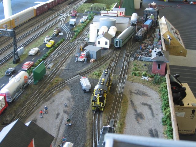
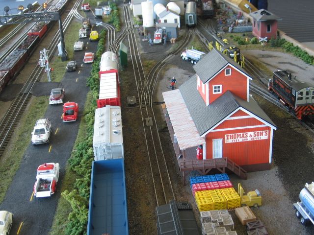
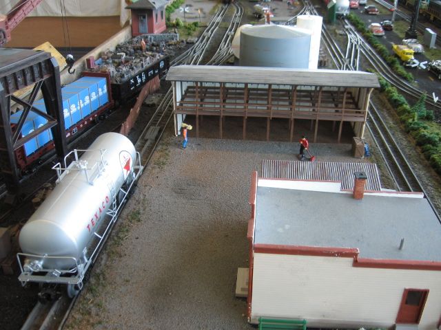
My switching is 30" x 19'.....


Looking to the right...


IMG_0129


Looking to the left...


IMG_0137


You have industries to spot in both directions, and 2 different run-arounds. I haven't worked on it in..... shoot I don't even know. The mainline is closest to the front, with a siding with cross-overs at each end. Mirrors on each end.  

Attachments

Images (2)
  • IMG_0129
  • IMG_0137

Kevin, which version of RR-Track are you using?  Back in December I "upgraded" from v4 to v5 (latest) because I had great expectations for the simulation view.  Unfortunately I have found it to be less stable than version 4, and version 5 does not let you save in a format compatible with earlier versions of the program.  So any layout I edited with v5 can no longer be edited with v4 

^^^^^
Ted & Carl
 
Carl, thanks for the response to Ted.  Finally got around to sending off an e-mail to RR Track about the roadway displays on 3D view.  We'll see what happens.
 
Originally Posted by Laidoffsick:

My switching is 30" x 19'.....


Looking to the right...


IMG_0129


Looking to the left...


IMG_0137


You have industries to spot in both directions, and 2 different run-arounds. I haven't worked on it in..... shoot I don't even know. The mainline is closest to the front, with a siding with cross-overs at each end. Mirrors on each end.  


I like the mirror idea and how it makes the layout look larger.  Things to consider.   I have another question on my layout that I will have to ask on the Subway Forum.


When I do start construction, I guess I will start a "My Layout Construction" thread and give periodic updates.

Add Reply

Post
The Track Planning and Layout Design Forum is sponsored by

AN OGR FORUM CHARTER SPONSOR

OGR Publishing, Inc., 1310 Eastside Centre Ct, Suite 6, Mountain Home, AR 72653
800-980-OGRR (6477)
www.ogaugerr.com

×
×
×
×
Link copied to your clipboard.
×
×