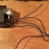
I have purchased what has been identified to me by Bill Davis as a Pioneer PRR k4, the first Japanese engine imported by Max Gray in 1957. I plan to restore it.

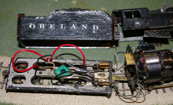
So far I'm in the process of stripping the paint from engine and tender. After removing the shell I see a motor of a type I am completely unfamiliar with. Can someone identify the type? I assume the round item is a resistor of some sort that feeds current to the field and rotor. Can I just put some voltage on the tender and frame contacts to see if it runs? It turns freely and smoothly.

Thanks, Jim


k4 1k4 2k4 3k4 4

Attachments

Images (4)
  • k4 1
  • k4 2
  • k4 3
  • k4 4
Original Post

Replies sorted oldest to newest

I have no experience with an MG motor that old.    The newer permag motors that max grey used have a reputation for being slow, ie low rpm at 12 v.    Or at least lower than many people like.   I have had this experience with a few MG locos and I have replaced the motors with newer ones.  

However, if this runs at a speed you like, I would say stick with it.  

I put 12 vdc on the contacts and got nothing. My only power source is a 4 amp battery charger. The ammeter gave a slight flicker when I applied the voltage but remained at zero. There was no measurable voltage across either the brushes or field coil.

Can anyone direct me to a schematic or explanation as to how this should work? My preference is to keep the locomotive original - I don't have a layout, but would like it to run. A replacement motor would be a last resort.

Jim

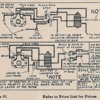
I found a wiring diagram for a Scale Craft universal motor on an OO site. My motor is wired the same way. I did check all the connections; they are secure and I have continuity through all the wires. There is continuity through the field coil as well.

The motor ran for an instant when I connected the field wires to the brush wires then applied power. The rectifier wiring was left in place. I think the rectifier is bad. I've scoured the internet to find another but can't even find a picture. The OO site shows a modern substitute but gives no information as to sizing. The original was called a "stack rectifier".

SCmotorRectifer

Here is the substitute rectifier and the supplied wiring diagram.


Scale-Craft-Universal-motor-rectifier 1Scale-Craft-Universal-motor-rectifier 1S-C-Universal-rectifier

Attachments

Images (3)
  • SCmotorRectifer
  • Scale-Craft-Universal-motor-rectifier 1
  • S-C-Universal-rectifier
Last edited by jjscott

The other drawback of the original motor is it will draw up to 3 times the amperage (around 5 amps) of a can motor.  The reason for this is there are no magnets in the original motor. That's the reason a rectifier is needed.

I went through this with my first Lobaugh Berkshire. The  stock motor overheated a 350 watt bridge rectifier!

Add Reply

Post

OGR Publishing, Inc., 1310 Eastside Centre Ct, Suite 6, Mountain Home, AR 72653
800-980-OGRR (6477)
www.ogaugerr.com

×
×
×
×
Link copied to your clipboard.
×
×