Hi all,

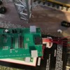
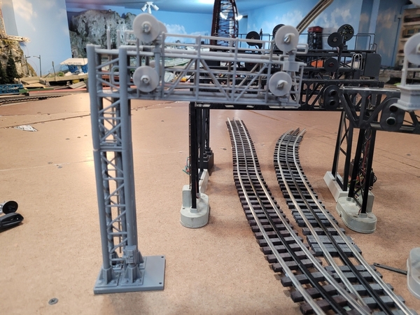
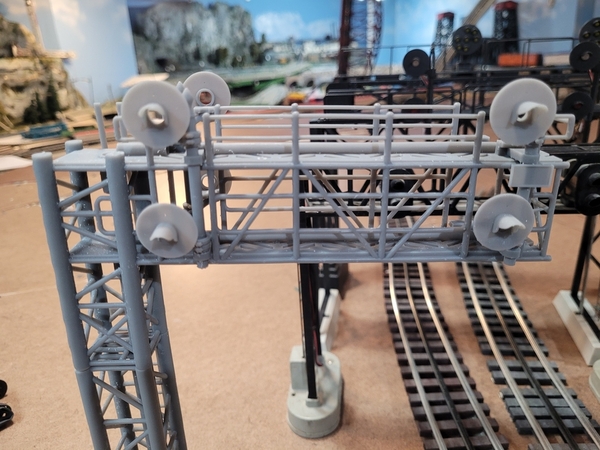
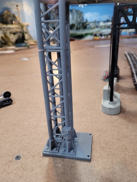
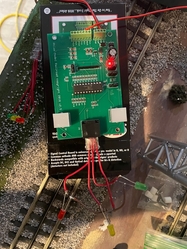
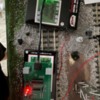
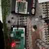
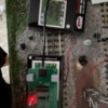
I have been working on a project over the last year or so of scratch building/completing a modern signal bridge (4 signals). As you can see in the pictures attached below, the actual structural features of the signal structure and the signal heads (3d printed) are almost entirely completed. I am now in the portion of trying to use leds and make the signal functional by connecting the leds to a phone jumper plug to connect to the Atlas universal signal control board as shown in the picture below (like a typical Atlas signal). I would like to use the Atlas signaling system as I have many other signals from them and am currently very satisfied with how it works.

However, as of now on the test leds that are connected to the control board, I have had no luck in getting any sign of life from them and they remain unlit. I was wondering if anyone has attempted something similar before? Or can provide guidance on what to do or try. (Circuit boards and wiring are not my forte)

Currently, I am focused on just getting the signals to function as a typical atlas signal does out of the box. In the future, however, I have also purchased an Atlas interlocking control board since the signal bridge sits in front of a crossover as it would in real life, so eventually I would also like to use that to control the signals as well.

Thanks,

Jack

Attachments

Images (2)
  • Signal Picture 1
  • Signal Picture 2
Original Post

Replies sorted oldest to newest

As a telephone technician with 60+ years of experience, I can suggest that you may have not made reliable connections in the modular plug.  It is a common problem when crimping modular plugs onto wires that the blades inside the plug do not completely penetrate the insulation of the wires. Try taking an existing, factory-made 4-conductor telephone cord, terminating in a 4-conductor plug, and cut it to a short length, exposing the 4 conductors, then make the temporary LED connections.

Last edited by Arthur P. Bloom

One other thing you could check ... look at the bottom of the Atlas circuit board where the jacks are connected.  I can't tell from the photo, but they appear to be RJ11 jacks.  RJ11 come in multiple flavors, 6 Position (P), 6 Contact (C) ... 6P4C.  Make sure the wiring and plug you're using match the number of pins soldered on the PCB.  Best of luck.

bd

Thanks for all your replies!

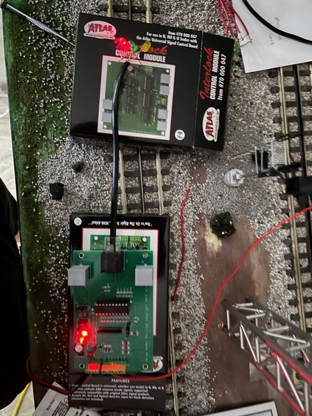
I have been working through all the suggestions and double-checking all my wiring and components. I have verified the plugs that I am using (RJ45's) and also that the leads are in the correct spots when crimped. Currently, I have the Universal Signal control board wired as follows with the custom plug and the leds:

Universal Control Board Wired 1

This seems to be where the problems start as while wiring all the leds together, I continued to test them using a battery to make sure that they would still light and function properly. However, once crimped in the plug and connected to the circuit board, the leds remain unlit. I even tried unclipping the plug from the board and holding the leads from the battery (2 Double A's for roughly 2.5-3 Volts) on the individual leds while still hooked together and they still remain unlit. (Is there a reason for this? The only thing that I can think of is that since the wires terminate in the phone plug this might create in a certain way an open circuit...). Because then as soon as I cut the wiring off one of the leds and effectively remove it again from the phone plug, when I hold the leads to it from the battery it goes back to being lit again.

And to make sure that I had the Universal control board wired correctly in terms of power and insulated rail wire, I took an Atlas type G signal and plugged it into the board and it functioned as it should.

One thing I have been considering is that the Atlas Universal control board outputs 5 volts before passing through a series of 3.3k ohm resistors, so is it possible that these leds (specs are 5mm diamter, 3volt, 20 mA)  are not recieving enough power to actually show any sign of light from the control board? Likewise, what would be the final voltage that the leds would be recieving after passing through the resistors?

Thanks again for all your help so far!

@JB8051 posted:
One thing I have been considering is that the Atlas Universal control board outputs 5 volts before passing through a series of 3.3k ohm resistors, so is it possible that these leds (specs are 5mm diamter, 3volt, 20 mA)  are not recieving enough power to actually show any sign of light from the control board? Likewise, what would be the final voltage that the leds would be recieving after passing through the resistors?

An LED in series with 5VDC and a 3.3K will light up plenty bright for you to clearly see it.  Why not take voltage readings and see what is happening?

As Art & Alan recommended determine if your LEDs are common anode or common cathode and confirm the jumper position on the Atlas board.  As GRJ recommended use a voltmeter to determine what is happening.  If it were me I would confirm the plugs are providing battery & ground where you think they should be (to the proper pins  on the jacks).  It's very easy to get them reversed and it's an easy test.  As always should any of your force be caught or captured the forum will disavow any knowledge.

bd

I am happy to report good news!

All the pins and jacks pins/jacks seemed to be working (verified with the voltmeter) and the jumpers were set to the correct common (cathode).

I spoke with Steve from Atlas earlier in the week (big thanks) and he suggested using 4-line phone cord to wire the RJ45 phone jack with. So, I ordered some and it arrived today. And as soon as I used it to wire a new test plug and plugged it into the universal control board, everything worked as it should like a normal Atlas signal!

I am thinking that previously the wire that I was using of just about 20-22 gauge stiff copper was just not compatible to use and might have been shorting out when put in the phone jack.

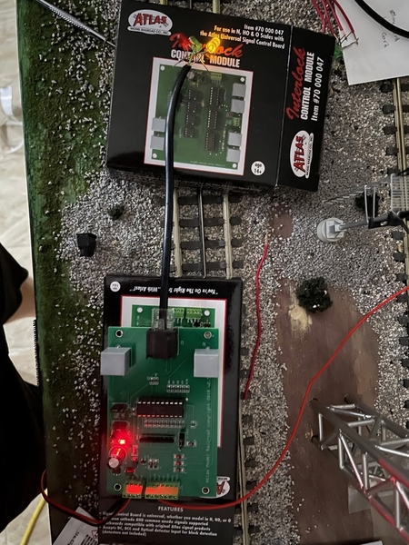
Here are the photos of the leds as they cycle through each indication.

Signal GreenSignal RedSignal Yellow


Now its time to use the 3d printed signal heads and wire the leds into them to finally make the signal.

Thanks for everyones help to get to this point!

Attachments

Images (3)
  • Signal Green
  • Signal Red
  • Signal Yellow

Add Reply

Post

OGR Publishing, Inc., 1310 Eastside Centre Ct, Suite 6, Mountain Home, AR 72653
800-980-OGRR (6477)
www.ogaugerr.com

×
×
×
×
Link copied to your clipboard.
×
×