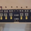
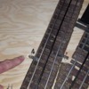
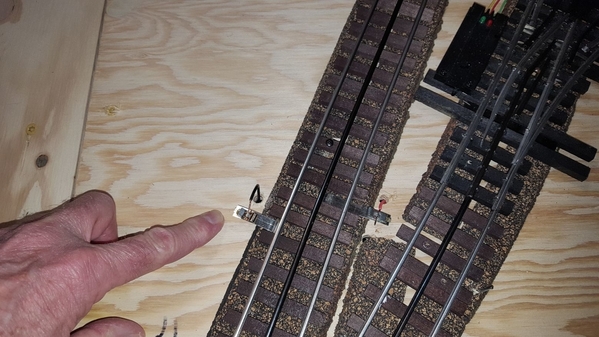
On my last layout, I must have don 20 sidetracks with blocks...now 10 years later on the new layout, i can't seem to get it right. The pictures show the Atlas blocking device and the power red and gound black placed on the track to be blocked. On the same rail as each wire is attached, I put insulating plastic pins, with a normal track pin on the third rail. Cannot shut off the power when hitting the yellow on / off switch. Any idea what's going on??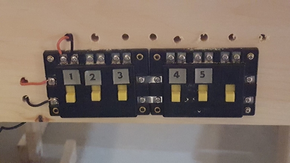
Replies sorted oldest to newest
So, let me get this straight. You have an insulating pin on the center (black) rail. Your switch (looks like an Atlas) is switching + power to the center rail. I presume at the next track joint. Can't tell if the is a stub siding, or a passing siding. If it is a passing siding there needs to be an insulating pin at the other end of the siding.
Tom, it's a stub siding...two insulating pins...one in the black center rail and one on the left rail...power and ground wires go to these two rails. The right hand rail has a normal track pin...
OK, if you want to isolate a stub siding. Put the insulating pin on the center rail. Switch power to your siding at the next joint of the center rail. Outer rails both get the conventional pins. No need to isolate them.
Thanks, Tom...I'll do it that way...after 10 years, it's like learning the wiring all over again...
You don’t need an insulating pin in the “left” (outside) rail. Only the center rail needs to be isolated.
You run power from the transformer (red wire) to the input side of the switch (the terminals on the left side, or end, of the switch) and another red wire on the output of the switch to the track.
Done.
The atlas 205 selector ONLY shuts off the bottom terminal/wire to the righthand/wire. The top is constant to the lefthand. You are currently only shutting off the one outside rail
Thanks for you input Rich and father.dragon...
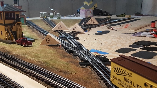
Hi...I'm back again and still dealing with a mystery. I have insulating pins in the center rails located at a "B" wood triangles...all going to the the switching yard area, with a 3 way to the right. All switches are Ross and track is Gargraves. All stubs are dead ends.
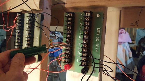
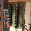
A single red power wire goes from the center track on the opposite side of the insulating pin to the Atlas Connector device for all of the the six blocked areas shown in the picture below. From the right hand side of the Atlas Selector, a red power wire goes to the power side of the MTH terminal block. The MTH terminal block red and black wire at the bottom go to the transformer. The other red and black wires shown on the terminal block are for track power for the main line and located 6 feet apart.
The issue is that the power to the track does not shut off on the opposite side of the insulated pin. The power on / off switch is not doing the job, although I suspect something is wrong with my connections...any thoughts appreciated! See pictures below...
Attachments
Capetrainman,
The Atlas Connector is probably not the most ideal on/off switch to use, but it will work if wired properly.
Looking at your picture of the Atlas Connectors, on the right side of your three ganged units, you have a red wire connected to the upper terminal. Move this wire to the lower terminal.
Above each one of your applicable on/off switches, you have the red wires connected to the left terminal. Move all of these wires over to the right terminal.
Your on/off switches should now work. I dug out an Atlas connector from my stock of parts and verified this with an ohmmeter. (I also verified that power is continuous through the terminals you are currently using, the on/off switch doesn't disconnect the power through the upper terminals and the left terminals).

Next thing, in your picture, you have a block triangle right in front of your 3-way switch. If you indeed have an insulating pin at this location, you should remove it. There is no reason at all to insulate the rail here (at least, none that I can see). And this will eliminate one block.
Hope this helps.![]()
Mixed Freight...thanks for the input...!
I have used Atlas Selectors and Connectors for 10 years. They work well for my Layout. Note the connector, it has one wire to the bottom screw on the right, and one wire from the right screw from each switch. Used as on / off for 3 yard tracks. The Selector below the Connector, the 4th switch with the arrow is the wire that goes to the Connector. This allows me to switch from throttle A or D on my ZW. The other switches on the Selectors are used for mainline blocks and yard lead tracks.
Steve
Attachments
I made the changes and tested all 6 blocks without an engine on the main track. All blocks turned on and shut off perfectly! Then i went ahead and put an engine on the main track, ready to enter the block arrangement, with the first block power on. When the lead engine got into the first block area, the power shorted out. In addition, the accessory post "B" on the ZW for all the building lights will not engage now and has a short? That short is unresolved no matter what I do. I run the ZW with 3 bricks. Train will run fine on main line with blocks turned off.
As a second test, the engine remained on the main track, with power to all blocks off. As soon as I pushed the on switch to Block 1, the power shorted out again. With all track power off, engaging the Accessory "B" power for the lighted buildings. the short on "B" occurs without any train powered on the main track.
Other than adding the new blocks described to the ZW, i haven't added any other accessories to the "B" post. Any thoughts are appreciated...
Never had even 1 electrical issue with my first layout...this one has be baffled![]()
Try to isolate the problem. Actually disconnect the wires at your control panel. Then start with making sure your main line blocks work OK. The one by one start hooking back up the wires to your yard lead or sidings. Make sure each works OK before going to the next. Do you have a common ground for all tracks. On my layout I use thermostat wire. Red for center rail and white for outside rail common. At my control panel all the wires for each block comes to 2 sets of terminal blocks. All white wires go to terminal blocks wired to the U sets of Post on my ZW. Each red wire has a second wire that goes to the Atlas Selector for that block. See picture below. Center slot are the wires coming in from the tracks on the layout. The 2 white wires on the left of the white terminal blocks go to the U Posts. Each red wire on the right goes to to each Atlas Selector for that given block. This is on the front side of my Control panel.
Here is the top of my control panel.
Control panel is a plywood box on casters
Back side. Terminal Blocks for O-22 switches, UCS Tracks, un-couple magnets, and accessory power.
Steve
Attachments
Steve, that's an impressive control panel. I do have grounds on the main line track connectors on the common rail along with each power red wire that go to the MTH Terminal Block. From there, power (red) and black (ground) go to the ZW. I removed the ground wires from the blocks and insulated the center rail only while supplying power to the center rail. That power wire goes to the Atlas Connector.
I'll begin the removal and testing process and report back. Along with the red power wire, should there be a ground going from the Atlas Connector to the MTH Terminal Block?
@Capetrainman posted:Steve, that's an impressive control panel. I do have grounds on the main line track connectors on the common rail along with each power red wire that go to the MTH Terminal Block. From there, power (red) and black (ground) go to the ZW. I removed the ground wires from the blocks and insulated the center rail only while supplying power to the center rail. That power wire goes to the Atlas Connector.
I'll begin the removal and testing process and report back. Along with the red power wire, should there be a ground going from the Atlas Connector to the MTH Terminal Block?
I'm not sure how you have that MTH Terminal Block set-up. If you look at mine, the outside rail wire, white, which is the common goes to my terminal block on the left in my picture. All of those terminals are connected by a buss or jumper wire, and go back to the U Post on the ZW. My red wires, the center rail from each block, make a connection to an individual screw on the terminal block on the right in my picture. They are separate from each other. The Wire in my center slot is coming from the track. The red wire connects to a screw on the terminal block. The wire on the right side of that terminal block goes up to the top terminal screws on my Atlas Selector on the control panel, in your case it would be your Atlas Connector. On the side of your Atlas Connector, from there you need to run your red wire back to your A or D post on your ZW.
On your terminal block, all the common wires are connected together. But, on the red wire from the center rail, each wire need to be separate from the other red wires. If that MTH Terminal block, all the terminals are joined to that large red knob on the bottom, that might be your problem.
Steve
Steve, my red center track power wires from the 6 blocks go to the Atlas Connector on the right side....a single red power wire goes from the lower right hand side of the Atlas Connector to the +side (red) of the MTH terminal block...did not use a ground here from the Atlas Connector. In addition to wires from the 6 blocks going to the MTH terminal block, there are four other red (power) wires and 4 black (ground (wires) from track connectors on the main tracks, all set 6' apart.
A single red and a single black wire go from the MTH terminal block to the "A-U" of the ZW.
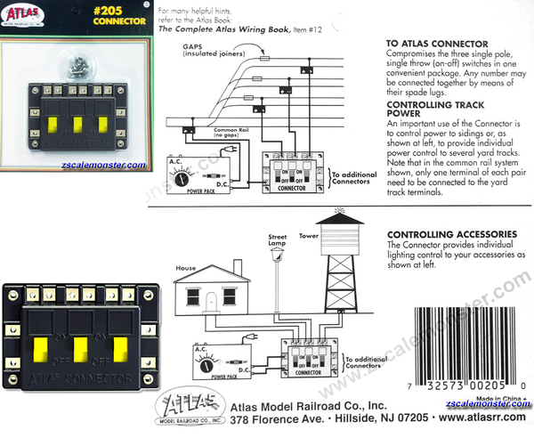
Here is the Atlas diagram for the Connector
Drawing shows for 2 rail HO track, but work same for 3 rail Lionel. The wire that comes out of the left side of the connector, that wire you could connect to that MTH Terminal block you have. This drawing shows only one common ground to the mainline track. You should run a common ground to each spur or yard track too. All the Common ground wires could connect to that side of your MTH Terminal Block that you are using for your common ground
Attachments
Thanks for the information Steve...I'll let you know how I do...
Steve, problem solved...it appears to be the proper grounding of all stubs that did the trick. Thanks for your detailed response, and thanks to all the other guys commenting on the problem. Now I can move on to placing the 3 stall Korber engine house in the yard area. It survived our recent move...let's hope it makes it safely on to the new rail yard![]()
@Capetrainman posted:Steve, problem solved...it appears to be the proper grounding of all stubs that did the trick. Thanks for your detailed response, and thanks to all the other guys commenting on the problem. Now I can move on to placing the 3 stall Korber engine house in the yard area. It survived our recent move...let's hope it makes it safely on to the new rail yard
Always satisfying to get a problem fixed. Show us your Engine House when it is done.
Steve


