I have an MTH SP Daylight with the fan driven smoke. I was thinking of adding a chuff switch to modulate the smoke and make it a bit more realistic. Has anyone done this? My thinking was to connect it to the fan so that I'd get a puff every time the switch closed. Any issue starting the fan motor continuously like that?
Replies sorted oldest to newest
I think this is the approach lionel took with the super smoke units. They used an ACREG item that also powered the smoke unit. I imagine it pulsed extra voltage to the fan unit, but I beleive it was driven via the R2LC vice a switch. Worst that can happen is wearing out a $6 fan motor early. G
Every smoke unit with a fan now does exactly that-turns it on and off at low speeds until you get going fast enough to turn the fan motor on continuously, so it shouldn't hurt anymore than we already do.....
Thanks guys, I wasn't sure exactly how they did that, I guess I never looked close enough at one that has fan driven smoke.
Seems like a pretty simple thing to do, a reed switch and one of the tiny magnets. ![]()
Are you running conventional? Chuff switches are useless if you're running conventional because the heating element requires constant voltage to stay hot and work properly with the fan turning on and off. If you're running dcc and your engine has chuff sound you could most likely wire the fan motor to the chuff board so every time the chuff sounds then the smoke will puff. I've not done this conversion to MTH but I have done it to Lionel.
Thomas
I'm running an MTH locomotive converted to TMCC using the ERR Cruise Commander. The MTH fan driven unit has the smoke heater and fan separately powered. I'm planning on having the smoke unit energized all the time, just flipping the fan on and off with the chuff switch.
The fan unit is wired seperately because your engine is running on A/C power supply and the smoke fan is D/C. your fan motor should be wired to a board in which The A/C power is driven thru the board and refigured to D/C before reaching the fan motor. If you unplug the fan motor and hook it straight up to track power it will run eratic for a few seconds then it'll pop with a whisp of smoke never to run again. The smoke unit can be rewired to puff with a two wire swap and a little resoldering on the smoke board if you have a sound board with chuff sound. Heres the easiest safest way : Take a 1 amp chuff switch and splice it directly into the power side of your fan motor then mount the chuff switch inside the steam chest where a drive rod can move in and out to activate the switch. Hope this will help you on your quest for the puff.
Thomas
Attachments
Thanks, I realize the motor is running from low voltage DC on the regulator board. Your description is exactly what I was considering, but I'm thinking of using a reed switch and a magnet, I think that will be easier to mount and get working. I also have a few of the tiny microswitches if that turns out to be the better solution.
A reed switch can be configured to trip more than once per revolution where as in most cases the chuff switch above can only be tripped once per wheel revolution giving you a less than desired prototipical chuff cycle. The reed switch is a good choice.
Thomas
I'll just have to figure out where to mount the magnet(s) to get the best sound. ![]()
I have to get the conversion finished first, I'm just starting on my custom lights in the shell now. ![]() I'm also waiting on the Cruise Commander kit so I'll have some power.
I'm also waiting on the Cruise Commander kit so I'll have some power.
It would be nice if someone has a picture or two of a conversion like this to post. I have been pondering doing this exact thing on a couple of Lionels that have continuous smoke. I guess I have been spoiled by PS-2 chuff smoke units and now nothing else looks right.
Rod
Well, I'll try to take pictures as I go, if it works out well I'll post them. ![]() If it doesn't work as I expect, I'll just bury the pictures and you'll never hear about it again.
If it doesn't work as I expect, I'll just bury the pictures and you'll never hear about it again. ![]()
I think the exact placement of the magnet or magnets will depend on the layout in an individual locomotive. The one I'm converting happens to be an MTH with PS-1, and there's no chuff provision. On the good side, I get lots of smoke from the smoke unit, so it bodes well for a conversion. I'm also faced with the issue of having to provide a separate chuff switch for the RailSounds board, so I may have to get creative there, perhaps a SPDT relay to provide isolated contacts for the two purposes. Decisions...decisions...decisions... ![]()
I don't think it'll work that great as PS2 reverses the fan motr polarity at each chug to stop the fan. Without the polarity change the fan motor will simply speed up and slow down.
Well, I can do a reversal without too much trouble if that's required. A DPDT relay or perhaps electronically. I'm going to be wiring a small board for the custom lighting anyway, so I'll have a place for a few more components. The nice thing about this locomotive is there is tons of space inside, so I have room to get creative. ![]() The Cruise Commander will be in the locomotive, and the RailSounds Commander will be in the tender.
The Cruise Commander will be in the locomotive, and the RailSounds Commander will be in the tender.
I might get by by just shorting the leads of the motor with the relay when I want to stop it, that will stop a freewheeling DC motor in a hurry.
John, Here is a part number Lionel uses. Your method probably less expensive.
| 691ACRGF04 | AC REG / SUPER SMOKE (04 CODE) |
Remember that the PS-1 smoke unit has a 2 stage element, depending on voltage. You may want to capitalize on that also. G
Well, the TMCC smoke output has a "turbo" function if you hold the "smoke on" key, but that's probably not what you're talking about. ![]()
I see that PS-1 smoke units have two resistors, but I thought they were simply wired in parallel. How does the 2-stage smoke work?
Do you have a reference for that Lionel part, I didn't find it.
MTH PS1 smoke units do not reverse fan polarity. However, be advised if you stop the engine w/power on unit while the fan is off for any length of time the unit can overheat quickly. If anyone wants a schematic of the PS1 smoke unit, email me at aglenney@sbcglobal.net
Good point on the overheating, I'll have to take that into account. It's looking more like a custom circuit to do the chuff management at this point. Perhaps I'd have to have a timer that if I didn't get a chuff for a couple of seconds, I'd just start the fan until I did. Time to dig out my supply of 555 timers. ![]()
John, No they wind up in series. The first number is the part number.
This is Lionels super smoke unit. I think there is documentation about a patent infringement with MTH. It is wired to the R2LC and the smoke unit to allow for chuff puff! :-)
I think your method wants to leave the fan on at a low voltage and use your chuff switch, or a modified timer to pulse higher voltage to simulate the higher smoke output.
Since you are going TMCC and will have full voltage, the current PS-1 smoke unit will have the heaters on full. You may want to look at the MTH web site they have info on the smoke unit in the service area, and you can look at the mod done to the unit if you do a PS-2 conversion. It includes cutting a trace on the smoke unit.
The regulator may be a more elegant solution, though a $30 one, but no additional switches and magnets. G
Actually, I like the idea of running the fan slow, then hitting it with a shot for the chuff, that might eliminate the issue of it overheating. The output of the R2LC is not full 18 volts, it's actually half-wave. When you apply the boost, you get the full wave output voltage, but I don't believe that's 18V either. FWIW, the smoke unit in this PS/1 locomotive is connected directly to track power, so it's getting whatever it takes to move the locomotive and cars.
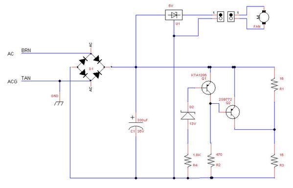
Got the schematic for the PS/1 smoke unit, it's more complicated than it would appear. The smoke resistors are in series, and they have a voltage switch to bypass to a single one when the voltage goes low, I guess to keep the smoke output up at slow speed by heating it hotter.
I had no idea how to find the service note you mention over at MTH, not the best designed site on the planet. ![]()
Here's what I came up with from the schematic from Allen, it was a bit blurred, so I drew a clearer one. Looks like you have to click on it to get the full resolution copy.
Attachments
Luckily I have a couple of turbo smoke units left over. But when someone comes up something that works like this let me know.
Turbosmoke units don't put a full 5 volts to the fan so you don't as powerfull a stream.
I might get by by just shorting the leads of the motor with the relay when I want to stop it, that will stop a freewheeling DC motor in a hurry.
John;
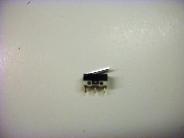
I think if you use a SPDT micro switch, you can use the leftover 3rd switch contact to effectively ground the hot wire to the motor when the juice to it is switched off. (Hope that makes sense.) In other words, the feed to the motor is alternately switched between hot and ground. This would kill fan rotation quickly.
If you were to use a reed switch and magnets, how would they be attached to the drivers considering how close the fit is between the inside of the driver and the frame? Just wondering what you had in mind?
John, I was assuming you would run the smoke unit from track voltage as it is now. If you run it from the R2LC it might smoke like a Lionel:-)
Yes, you have plenty of options. Run from track modified with a circuit to puff with Chuff.
Run from R2LC so you can turn it on and off and reduce the volume.
Run if from Track voltage via a relay controlled by the R2LC, so you still can turn it on and off.
Integrate the REG Board Lionel uses.
For the reed switch, you could mount it on the tender and run the signal in via a harness, which you may have to have anyway.
Not sure what the insides look like, but my J has plenty of room and a smaller than the motor Flywheel. A magnet or a trigger could be attached to the fly wheel and trigger a chuff switch or reed that way. That would also allow for more than one chuff on the reed switch.
What program is used to draw the circuit diagrams? Is it a free application?
The one element is on at 8Volts and the second comes on at 10-12 volts. G
I think if you use a SPDT micro switch, you can use the leftover 3rd switch contact to effectively ground the hot wire to the motor when the juice to it is switched off.
I've kinda' signed on to the idea of not turning the fan off completely, it makes perfect sense to just run it slow and then hit it with higher voltage for the chuff.
If you were to use a reed switch and magnets, how would they be attached to the drivers considering how close the fit is between the inside of the driver and the frame? Just wondering what you had in mind?
There's plenty of room in this shell to get creative, I could almost cram the Cruise Commander and the RailSounds Commander in there. I don't think there's any problem finding a place to tap off the motion for the chuff. I'm thinking of using the rod motion to trigger the chuff so it's synchronized.
John, I was assuming you would run the smoke unit from track voltage as it is now. If you run it from the R2LC it might smoke like a Lionel:-)
Good point, and I may well do that. I would use the R2LC output to at least drive a relay so I can turn off the smoke from the remote.
A magnet or a trigger could be attached to the fly wheel and trigger a chuff switch or reed that way.
The gearing appears such that a magnet on the flywheel would probably give me about 8-10 chuffs per wheel revolution, I think that may be too much of a good thing. I'd like to synchronize them with the movement of the steam pistons.
For the reed switch, you could mount it on the tender and run the signal in via a harness, which you may have to have anyway.
I'm sure I can put it in the locomotive, tons of space in there.
What program is used to draw the circuit diagrams? Is it a free application?
The application is TinyCAD and it is indeed a free application. The only issue with this one is the symbols for the transistors need work and they don't line up on the grid. Easily fixed, just too lazy to do it right now. ![]()
The one element is on at 8Volts and the second comes on at 10-12 volts.
Actually, the series string is always energized, it's wired directly across the incoming power. They're just using the switch to short out one of them for low voltages. When Q2 is turned on, it shunts R1 and puts the full available voltage across R3. For command operation, that circuit probably would never be energized. My only concern is that this unit probably isn't designed for a steady 18 volts, so it may overheat.
xxx
TAS used to make a board to do what you are trying to do. It was about the size of a quarter. Unfortunately a certain person (MW) threatened TAS with a lawsuit so they had to stop making it. Now if someone could come up with a schematic for it we could make our own.
I am not the electronic design guy, but conceptually, you can cut the trace and parrallel connect the resistors such as the PS-2 unit.
As far as using the flywheel, knowing the gear ratio you could create a circuit to divide the ratio and pulse depending on the chuff count you want.
Again, I think the guts of the circuit maybe in the Lio ACREG. I have one opened I will list the components. G
Still considering my options here. Got a couple other projects that pushed their way in front of this one. ![]()
Ever get back to this project? By the way, the circuit drops the extra resistor out at High voltage, not low voltage.
At Low voltage the 2 16 ohm resistor are in series giving a 32 ohm equivalent. As voltage goes above 13V the transitor turns on shorting one of the resistors out and giving a 16ohm equivalent resistance.
Which is interesting. At low voltage you get 2 low watt elements, and at high voltages you get one high watt element. G
Perhaps they wanted it to smoke more at high voltages to simulate the locomotive working harder. ![]()
This one's still in the queue, but I have a Tie-Jector on the bench, I'm converting it to TMCC and also installing a servo to activate the tie dropping mechanism. I was waiting on the Cruise Commander for the SP locomotive, so I got involved in another project. ![]()
"Perhaps they wanted it to smoke more at high voltages to simulate the locomotive working harder. "
Of course they do, but don't you get the irony? At low voltage you get 2 elements, but at high voltage to get more smoke they go to just one element.
I guess they came around with PS-2 and put both in parallel. ;-) G
I suspect that two elements may have drawn too much current at the higher voltages. About the only reason I can think of for the way it works.
John, Opposite effect. 2 resistors in series reduces current flow. These are the same 16ohm resistors used in the PS-2 engines. The PS-1 has them wired in series so each drops half the voltage of the track.
The PS-2 are in parallel and effectively 8 ohms, so the current draw is not the issue.
When the transistor conducts at high track voltage and shorts one resistor, the other then gets full voltage and increased current with an effective 16 ohm load. Just an interesting way to approach solving a problem. G
I'll have to take a look again, that really makes little sense, hard to believe it's supposed to work that way.
Hey Gunner,
This may not apply but it wont hurt to mention. I have a engine that had a plunger for the smoke, but a chuff switch for the well, chuff. I superglued the same exact size chuff switch next to the existing one (together)and conected the metal push in pedals.I added a fandriven smoke unit also.. The extra chuff switch is hooked to the fan. So they are in now in sync
John, Opposite effect. 2 resistors in series reduces current flow. These are the same 16ohm resistors used in the PS-2 engines. The PS-1 has them wired in series so each drops half the voltage of the track.
The PS-2 are in parallel and effectively 8 ohms, so the current draw is not the issue.
When the transistor conducts at high track voltage and shorts one resistor, the other then gets full voltage and increased current with an effective 16 ohm load. Just an interesting way to approach solving a problem. G
Actually, it works the way I thought it should. At low voltages, Q1 will be off, so Q2 will be conducting, shorting out the one resistor. When you pass the threshold of the zener and the base-emitter junction drop, Q1 will turn on, removing the base-emitter bias of the Q2, turning it off.
It makes no sense to have it work the other way.
Hey Gunner,
This may not apply but it wont hurt to mention. I have a engine that had a plunger for the smoke, but a chuff switch for the well, chuff. I superglued the same exact size chuff switch next to the existing one (together)and conected the metal push in pedals.I added a fandriven smoke unit also.. The extra chuff switch is hooked to the fan. So they are in now in sync
I'm planning on adding a chuff switch and relay, or simply two magnetic chuff switches. One will trigger the RailSounds chuff input, the other will modulate the fan.
John, Opposite effect. 2 resistors in series reduces current flow. These are the same 16ohm resistors used in the PS-2 engines. The PS-1 has them wired in series so each drops half the voltage of the track.
The PS-2 are in parallel and effectively 8 ohms, so the current draw is not the issue.
When the transistor conducts at high track voltage and shorts one resistor, the other then gets full voltage and increased current with an effective 16 ohm load. Just an interesting way to approach solving a problem. G
Actually, it works the way I thought it should. At low voltages, Q1 will be off, so Q2 will be conducting, shorting out the one resistor. When you pass the threshold of the zener and the base-emitter junction drop, Q1 will turn on, removing the base-emitter bias of the Q2, turning it off.
It makes no sense to have it work the other way.
John, You are correct on how the transistors worked, I was viewing it from the load side and how cutting in an additional 16 ohm resistor in series was effecting the current. I
From 6 to 13V the single 16 ohm resistor would draw .375 to .8125A and produce 10.56 Watts of heat. When Q2 goes off and the 2 resistors are in series at the transition point of 13V the current would drop to .406A and 5.28W output. Max W would be 10 at 18V. So the output would seem to dip at 14V and then flatten back out at 16-18 V.
This never gets over about .56 amps of draw.
If you kicked out a resistor at 13V, so the unit was on a single 16ohm resistor, you would get a jump of 5Watts at transistion, and Max out at 1.125A and a 20W at 18V! More linear response.
So it does seem like two elements produce more smoke than one even though the current is reduced in half. G
Did you have something to add? ![]()
Yes. Above, hit the wrong key:-) G


