
I was thinking about putting in a small fuse box. Looking at it I think the hot's would go through the fuses and the grounds from my 4 tracks would all have to go to 1 post before being separated to go to the common posts on the transformers. Would using one of these cause any issues?


fuse box

fuse box

fuse box

Attachments

Images (1)
  • fuse box
Last edited by Dave Ripp.
Original Post

Replies sorted oldest to newest

I suggest you consider using breakers instead of fuses for the train circuits, as it's cheaper in the long run.


Do be aware that also putting a fuse or breaker in the common leads running to each of the transformers would be a good idea, for protection of transformers.  For example, putting a 10-amp fuse in each of 4 hot outputs from a postwar ZW could result in up to 40-amps being drawn from the transformer, way too much.  That's why Lionel put the single breaker in the U circuit, which of course provided no protection against shorts between any 2 of the hot posts, possible when they are set on different output voltages. 

The fuse box in the second and third picture of the original post looks like it protects 4 branch circuits from a common feed. I assume you would hook it to the common terminal.
I don't think that is going to provide proper protection for a transformer like a ZW. Each "hot" terminal (A,B,C,D) needs to have it's own breaker (fuse). The main reason is to protect the transformer in the event a "hot" to "Hot" short is created, as RJR mentioned.

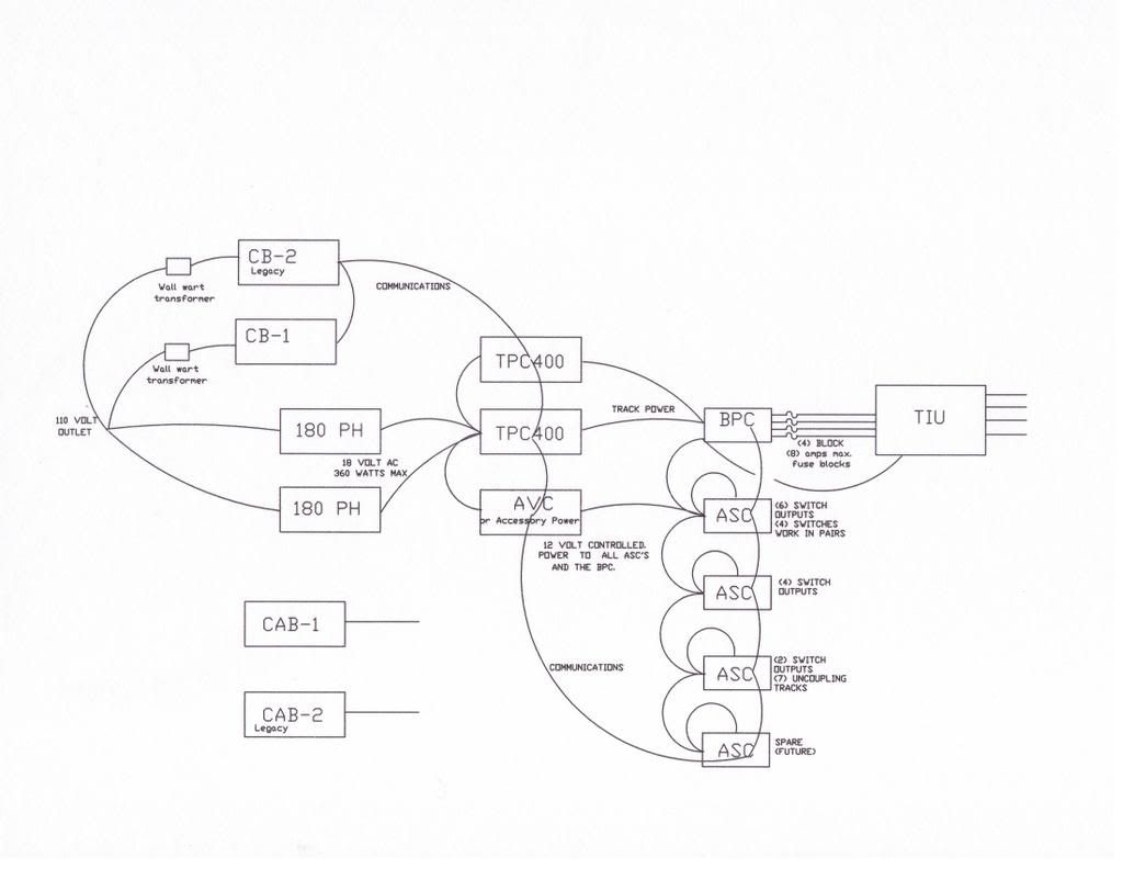
Here is the single line diagram for my power supply, note that a second BPC has been added. There is a fair amount of redundant protection, though the smallest overload protect always opens first, (7.5 amp track circuit fuses) and (3 amp accessory fuses) When I did the Atlas 6924 relay board upgrade, I eventually added (3 amp fuses) in the power routing circuits, after a few of the 6924 boards fried traces fused at 7.5 amps. Note that the 6924 relay boards are rated at 8 amps.

Single Line Diagram

(1.) Primary power source is (two) parallel PH 135's  about 270 watts of power. Each PH 135 has a 7.5 amp cut-out/reset.  In parallel that would be 15 amps of track power, both cut-outs have tripped simultaneously on dead short derails.

(2.)  Each TPC (Track Power Controller) 400 has a 20 amp cut-out.  These cut-outs have never tripped on my layout.

(3.) The parallel power source, PH 135's, is Input power to the TPC 400.

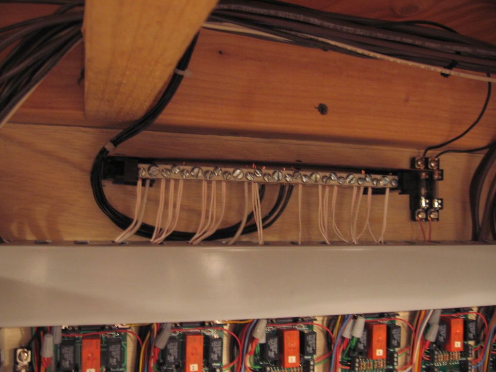
(4.) Output of the TPC 400 is distributed to the input of a BPC, (Block Power Controller) with (4) outputs.  

(5.) These older IC Controls BPC are rated at 15 amps. Unfortunately 15 amps of dead short de-rail was enough to fry contacts on a couple of these devices so I added individual track circuit protection after the BPC's (7.5 amps) per track circuit.


(6.)  Circuit limits.

Track circuits.  7.5 amps.

Additional 6924 relay board protection 3 amps.

Accessory protection.   3 amps per circuit, some are fused at 1 amp.

TPC and PH135 protection  is parallel 7.5 amp cut-outs on the PH135's.


7.5 amp track fuse open first on the track circuits.


There is no fusing in the common circuits, it is not required.  Even in all the wiring I've done in the last 40 years no fusing was ever installed in common or common ground circuits.  You would have to go back to knob and tube wiring to find fuses in the common ground circuits.

An upgrade single line diagram with larger power supplies and (2) TPC's


Last edited by Mike CT

Then the ZW or for the matter a Z 4000 needs to be fixed so that it is self protecting. My PH 135 are self protected.

The club Z 4000's appear to open both track circuit, (shut down), when you exceed 10 amps on either track circuit.   My thought is that's the way it should be.  We sent a Z4000 back for repair when it didn't function properly on overload exceeding 10 amps. MTH fixed it.   

Originally Posted by C W Burfle:

According to the tables in the 5F test bench manual, an internal ZW breaker should trip within 11-17 seconds with a 30 amp load.

That's for a Postwar Lionel ZW transformer, I don't have information on the modern era ones.

I reset my case, that's way too long for 30 amps!


Originally Posted by Mike CT:

Then the ZW or for the matter a Z 4000 needs to be fixed so that it is self protecting. My PH 135 are self protected.

The club Z 4000's appear to open both track circuit, (shut down), when you exceed 10 amps on either track circuit.   My thought is that's the way it should be.  We sent a Z4000 back for repair when it didn't function properly on overload exceeding 10 amps. MTH fixed it.   

The old PW-ZW is an old design, no surprise there.  We've come a long way since then.  Of course, the PowerHouse supplies don't have a problem, they only have one output.  Any of the transformers that have multiple outputs have a potential issue unless they're designed for that.  The Z4000 does take total load into account, 10A per channel, and it's capable of delivering 20 amps.


GRJ is absolutely correct.


What is said above about no fusing in common ( read neutral) circuits in house wiring is correct.  IN more than 40 years, I've never done it either, but in a house we don't have the possibility of multiple breakered feeds returning through a common wire, if wired correctly.*


*I came across one installation by a supposedly reputable electrician, where he took a 3-wire 12-gauge circuit off the breaker box, but took both hots off the same side of the line (BAD!), meaning the white wire (neutral) could have been carrying 40 amps.  This is what can easily happen on a layout.

As I understand the pw ZW it is a single coil[winding] with four pickups taken from the one winding. With out regard to how distributed between A,B,C or D; it has a maxium output of about 10-11 amps depending whom you are arguing with. But after time it does lose efficiency and trend downward.


Now, as I also understand the pw ZW, its four outputs--A,B,C&D cannot exceed the capacity of the single secondary winding or, about 10-11 amps on a primary input of 275 w.


I do not understand where the 40 amp output/build up arises??? 


John!?


Last edited by Dewey Trogdon

Dewey, get your trusty clamp-on meter out and put it around all the neutral leads going from the ZW transformer.  Then, just short-circuit one or more outputs directly to the common, you'll see a lot more than 10 amps!  If you can draw more than 10 amps that way, you can draw more than 10 amps by simply loading multiple outputs.  Sure, the voltage will drop, but it will deliver a lot more than 10 amps for a short period of time.  Remember the 25A rating on the common breaker?

Post

OGR Publishing, Inc., 1310 Eastside Centre Ct, Suite 6, Mountain Home, AR 72653
800-980-OGRR (6477)
www.ogaugerr.com

×
×
×
×
Link copied to your clipboard.
×
×