So at menards today I came across some 4.5 volt crossing signals, dc powered with a transformer ...scale-ish...problem is they are on all the time.

Does anybody know of a setup that will activate/deactivate 120 volt ac so the transformer power can be turned on/shut off by a passing train?

These are inexpensive little devices...just need a device to control the power so they can be made to operate similar to the real thing...

Any ideas?

Last edited by gibson man
Original Post

Replies sorted oldest to newest

I'm guessing that you don't want to cut into the low voltage wires and control it that way? I would do it using the low voltage route. 

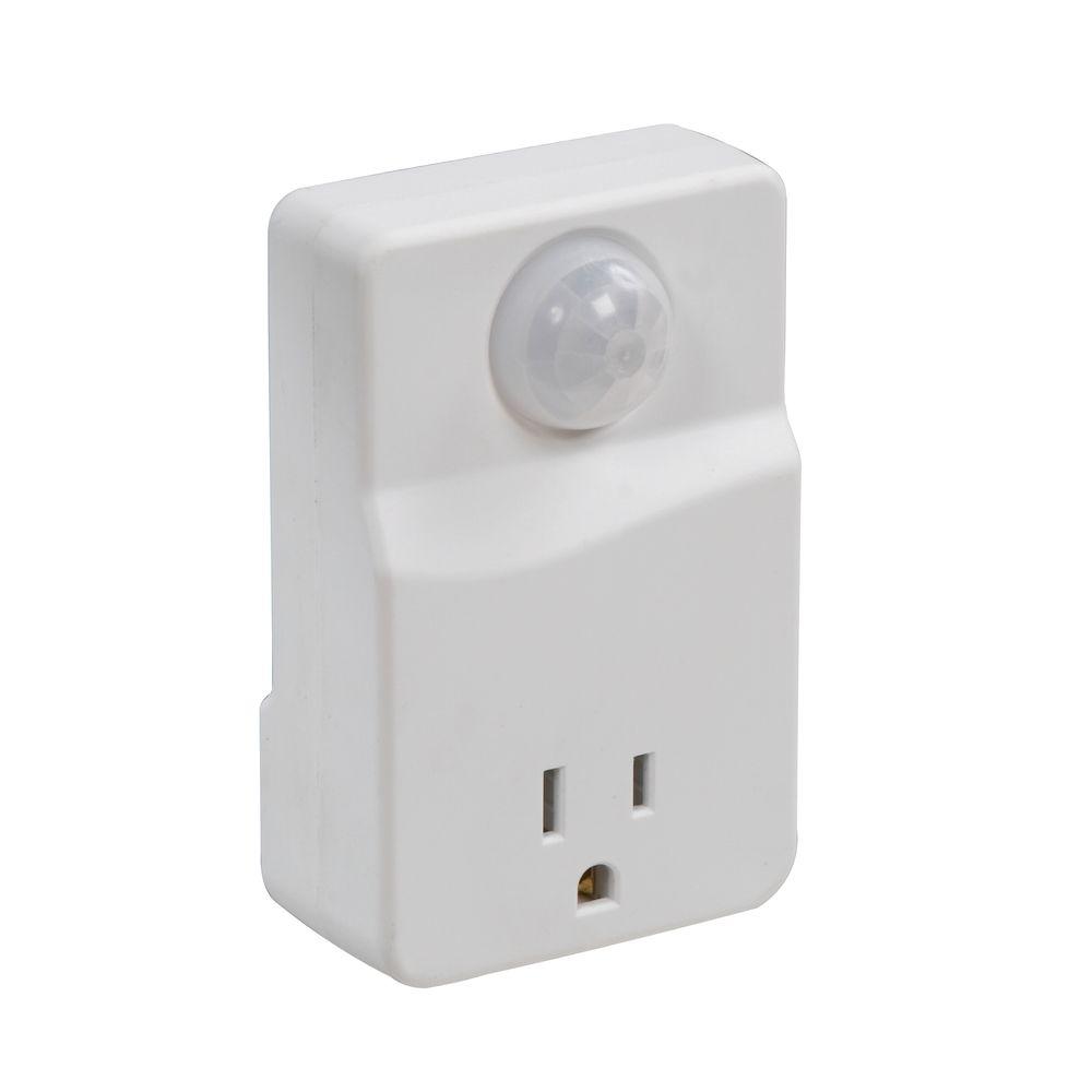
However you can control the 120 with something as simple as the motion activated switches or plug modules. 

searching for "120V Motion activated plug" turns up several items on Amazon and the Home Depot as seen here. 

Westek Plug-In Motion Activated Control

Last edited by enginEErjon
gibson man posted:

So at menards today I came across some 4.5 volt crossing signals, dc powered with a transformer ...scale-ish...problem is they are on all the time.

Does anybody know of a setup that will activate/deactivate 120 volt ac so the transformer power can be turned on/shut off by a passing train?

These are inexpensive little devices...just need a device to control the power so they can be made to operate similar to the real thing...

Any ideas?

This is copied from another thread discussing these signals that are battery powered.

“TedW posted:
ADCX Rob posted:
You can use a 145c contactor or the insulated rail technique. There's nothing special about these that would preclude either method.

... what wire do you break to hook to the rail? ...

Either one anywhere. One loose end to common / lockon clip 2 anywhere on the layout, the other to the insulated trigger rail with another lockon - clip 2 clipped to the insulated rail.

I have used AA rechargeables in these and they will operate continuously for a week or more, so they should last a long time when triggered only by a passing train.

For more reliable operation, as with many insulated rail activated accessories, you could use a relay to switch the power to the device.

Rob”

Can the 153 ir be used as just an on/off switch...in other words...could I split on side of the line from the 4.5 volt dc transformer (on the dc side, not the ac side),  run it through the auxiliary side of the 153ir, and use that as the switch to turn the lights on/off...or do both sides of the 153ir see track voltage?

gibson man posted:

Can the 153 ir be used as just an on/off switch...in other words...could I split on side of the line from the 4.5 volt dc transformer (on the dc side, not the ac side),  run it through the auxiliary side of the 153ir, and use that as the switch to turn the lights on/off...or do both sides of the 153ir see track voltage?

Since the 4.5V DC transformer is electrically isolated from your AC Aux supply, you can connect one side of the 4.5V DC to one of the AUX power wires to be switched off/on at the 153IR "NO" terminal.

enginEErjon posted:

...

However you can control the 120 with something as simple as the motion activated switches or plug modules. 

searching for "120V Motion activated plug" turns up several items on Amazon and the Home Depot as seen here.

PIR (Pyroelectric InfraRed) motion sensors are generally used to detect human activity and as such detect motion of a heated object.  Yes, run an engine for a while and it heats up to more than body temperature.  OTOH freight cars would remain at room temperature and hence never trip a PIR motion sensor.  Additionally, motion is required to trigger a PIR sensor.  So a hot engine stopped right on the crossing will not trigger... not so impressive an occupancy-sensor!

Could you describe the wiring scenario?

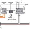
What I am visualizing is separating the 4.5 dc output wires...splitting one of those wires...routing the output from the transformer side of the split wire from the transformer through the 153IR (where do i connect this wire end?)...where then would I connect the other end of the severed wire to get continuity when the switch activates?

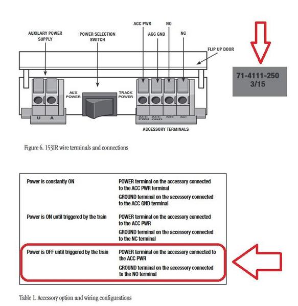
153ir pic 1

I have read here on OGR that the 153IR has undergone revisions that, if memory serves, may affect this wiring scenario.  I am referring to the version shown above with the applicable operational mode circled in Red.  I have personally opened up this version of the 153IR to confirm it is internally wired to operate as indicated.

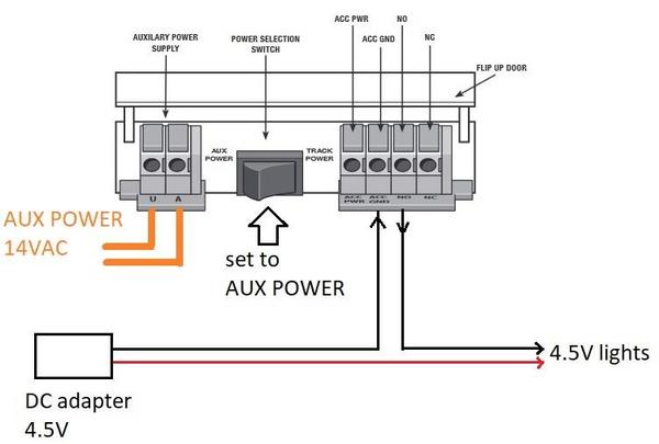
153ir pic 2

The diagram above shows the "black" wire of the adapter being split.  I realize the 2-wires from the Menards adapter aren't red and black.  It doesn't really matter which wire you split.  If given a choice and you have a meter and know how to use it, I'd split the "-" side of the 4.5V DC.  But again it doesn't matter.

Attachments

Images (2)
  • 153ir pic 1
  • 153ir pic 2

Add Reply

Post

OGR Publishing, Inc., 1310 Eastside Centre Ct, Suite 6, Mountain Home, AR 72653
800-980-OGRR (6477)
www.ogaugerr.com

×
×
×
×
Link copied to your clipboard.
×
×