Hello all,

I recently took possession of a Weaver CN U4a. It's a gorgeous engine, with super basic TMCC and a fan driven smoke unit (a TrainAmerica one.)
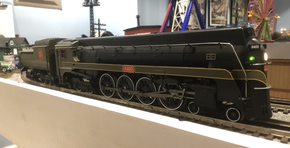
U4a #6400

I plan to convert this engine to PS3, as all the other Canadian steam I own is already PS2 or PS3 (Except for one, more on that later)

This thread is mainly a project thread (as well as a guide for others, who like me are super confident.) This is my first attempt at converting an engine to PS3.
I do have a few goals for this project:
1. Convert the engine to PS3. (I prefer MTH more than TMCC. Nothing against TMCC, I just like the DCS more.)
2. Repaint the engine (not fully, just a few minor changes)
3. Convert the lighting to LEDs.

Having opened up the engine, there are already a few interesting quirks.
1. There is a beefy Pittman motor with a nice 31.8 mm flywheel. The only issue is that the flywheel is on a 1/4" thick (quite thin.)
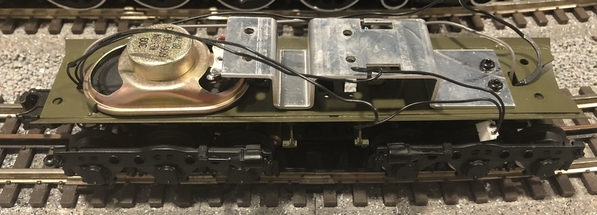
2. The vanderbilt tender has a what seems to be a odd 8 Ohm speaker; a 65mm by 35mm oval speaker to be precise. It's fit to the frame, as the brackets that hold it down are literally part of the tender. The speaker sounds fine. Based on my limited knowledge, I believe I can re-use it (someone correct me if I'm wrong.)
3. The cab is nicely detailed, but not painted. The engine comes with a firebox glow courtesy of two LEDs slapped on to the Pittman.

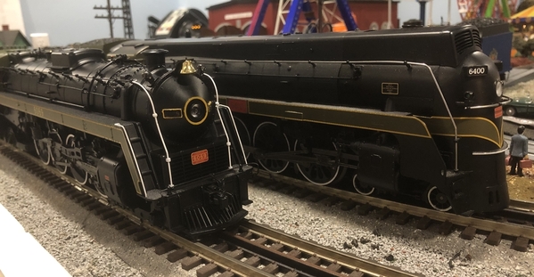
I'll leave the end of the first post with a picture of the U4a with one of it's stablemates, a U1f.
U4a #6400 and U1f #6069

Attachments

Images (2)
  • U4a #6400
  • U4a #6400 and U1f #6069: U1f #6069 recently emerged from both the paint shop and audio shop. The engine itself is MTH 20-3498-1 (a set.) I've touched up the hand rails and front with a more true to the prototype look (look at all that yellow.)
Original Post

Replies sorted oldest to newest

MTH uses a 4-ohm speaker in the PS 3 upgrade kits.  The included speaker is okay but there is room for improvement. I've been using the Dayton Audio DMA58-4 with a custom baffle wherever possible.

PS3 Steam upgrade kits are made to drive incandescent bulbs so to convert to LEDs will require your own LEDs and resistors to replace what the engine has now.

I wouldn't worry too much about the thin flywheel. The tack tape can be cut to fit, make sure tach reader will still line up with the flywheel.

Last edited by H1000
@H1000 posted:

MTH uses a 4-ohm speaker in the PS 3 upgrade kits.  The included speaker is okay but there is room for improvement. I've been using the Dayton Audio DMA58-4 with a custom baffle wherever possible.

PS3 Steam upgrade kits are made to drive incandescent bulbs so to convert to LEDs will require your own LEDs and resistors to replace what the engine has now.

I wouldn't worry too much about the thin flywheel. The tack tape can be cut to fit, make sure tach reader will still line up with the flywheel.

Seems nice. Have you installed it into a Vandy tender? Tuff to fit some stuff in there.

@BBasalik posted:


1. There is a beefy Pittman motor with a nice 31.8 mm flywheel. The only issue is that the flywheel is on a 1/4" thick (quite thin.)
2. The vanderbilt tender has a what seems to be a odd 8 Ohm speaker; a 65mm by 35mm oval speaker to be precise. It's fit to the frame, as the brackets that hold it down are literally part of the tender. The speaker sounds fine. Based on my limited knowledge, I believe I can re-use it (someone correct me if I'm wrong.)
3. The cab is nicely detailed, but not painted. The engine comes with a firebox glow courtesy of two LEDs slapped on to the Pittman.

1. As long as you can get a tach tape on it for the stripes, it should work.

2. You can re-use the speaker. It won't be as loud because it has a higher 8 ohm coil.

Seems nice. Have you installed it into a Vandy tender? Tuff to fit some stuff in there.

That's going to be a tight fit if it fits. It might fit under the coal load but will there still be enough room for the board??

If you can get it all in there the speaker is well worth the upgrade. Below are the dimensions of the DMA58:

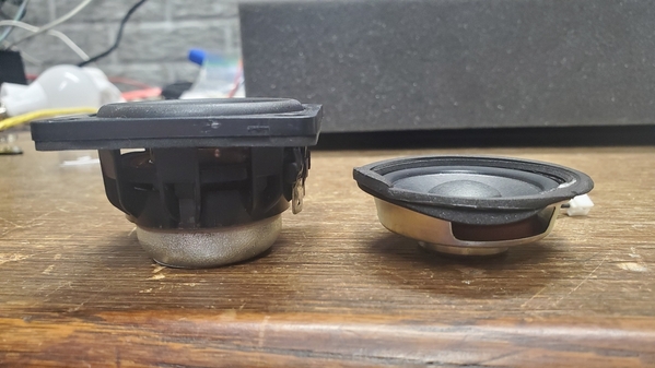
Here is a side profile comparison between the stock MTH speaker and a DMA58:
20230405_233600

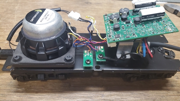
And here is one installed in a Railking R-T-R Tender:
20230406_004337

Attachments

Images (3)
  • mceclip0
  • 20230405_233600
  • 20230406_004337
Last edited by H1000

I appreciate the suggestions!
At present I may have to replace the speaker. It may be 8 Ohms, but it is also only a 2 Watt speaker. I believe I've read on the forum that the amplifier on the PS3 board puts out 4 watts. The speaker can handle the Ohms, but I don't think it could handle the Watts.

I have an idea, just from looking at some MTH speaker enclosures I have lying around. Perhaps I can put the speaker on it's side in the water tank part of the tender.

@BBasalik posted:

I appreciate the suggestions!
At present I may have to replace the speaker. It may be 8 Ohms, but it is also only a 2 Watt speaker. I believe I've read on the forum that the amplifier on the PS3 board puts out 4 watts. The speaker can handle the Ohms, but I don't think it could handle the Watts.

I have an idea, just from looking at some MTH speaker enclosures I have lying around. Perhaps I can put the speaker on it's side in the water tank part of the tender.

think of the speaker ohm rating as a draw on the amp, not the speaker.

Figured I post the first update.
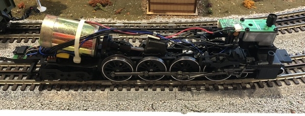
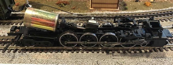
I gutted the engine, so all that’s left now is the motor.

Pre:

IMG_5436
Post:

IMG_5438
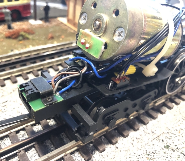
I saved all the old electronics, as you never know when they might be useful (a later project perhaps.) I plan to replace the smoke unit with an MTH one with an equivalent stack height. The fun part now begins with as I attempt to figures out how to mount the tether end.

IMG_5437
Unfortunately, this won’t be a case of just dropping it in, a la the directions in the manual. I can’t reuse the old bar, as then the tether is upside down.
At present,  I’ve come up with a solution to use 2 8-32 nuts to serve as mount. I’ll attach them to the frame. The real question is to use nylon or metal.

Attachments

Images (3)
  • Old electronics
  • No Electronics
  • Old tether
Last edited by BBasalik

Get long 2mm at hardware store.  You will have to custom drill into the pcb after locating over exsisting chassis holes.  Use the plastic spacers  that came with old PS-2 3V kits for the battery harness.  You have more fitting to do and making sure shell opening works too.  Don't be surprised if you need to file it open more.  G

I've done a few things, so here is the next update!

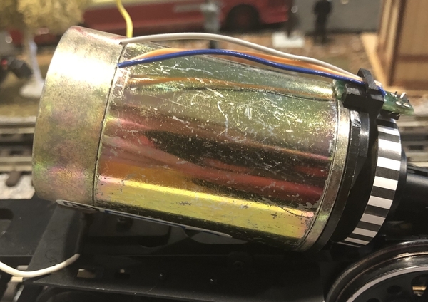
First was mounting the tach sensor and tach tape! This was an adventure in itself. The Pittman mount blocked interior hole inside the tach senor holder. I filed it down to eliminate the problem. Next, the stock MTH Pittman holder had to be modified a bit. Pre-modification, the tach sensor sat to far in front of the flywheel. Extending the flywheel wasn't an option, as then the dogbone joint became jammed a bit. I ended up filing out the interior of the holder for a snug fit, as well as removing the back part. The tach senor fit snugly and wires were secure. The sensor was a bit too close to the flywheel, so I worked it a little further away. A quick solder job on the motor leads (White is negative, Yellow is positive for those unware,) and the motor was done. Flywheel was a crisp 31.8 mm, so I merely cut the matching tach tape to the correct width.
See below:

U4a.TachUpgradejpg

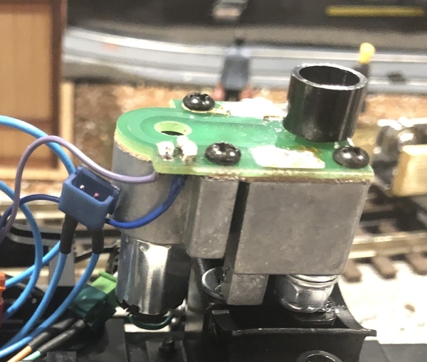
Next came the smoke unit. I found an equivalent MTH smoke unit in terms of size to the Train America one (MTH Part No. AA0000130) I used the original bracket, and built up a shim using nuts and washers. Cup height matched, as did location.

U4a.SmokeUnit

I had extra time today while listening to baseball, so I kept at it. Next came mounting the tether. I ultimately decided earlier on using the existing mounting holes in the tether, and using nuts and washers to shim. Little bit of experimenting, then using some adhesive on the nuts. The result was being able to drop the new tether receptacle right in. Some cable management later, and I was able to test fit the shell. No issues arose during this (which has to mean something is wrong right) and the shell fit perfectly. The only tweak was bending the smoke unit bracket slightly.

See below, for the finished wiring (the blue headlight wiring is coiled up in this photo, as I'm planning to tweak it when I add LEDs. I wanted to make sure the shell fit.)
U4a.EngineWiring

For those of you who are curious, the U4a shell is quite roomy. Weaver elected to use a long flat weight the runs between the 2nd and 4th drivers. With the shell on, there is still about 2 cm of space between the top of the gearbox and the weight.
With it being the 8th inning, and the Phillies not somehow imploding yet, I moved over to the tender. Stripping out the tender electronics was pretty easy. I left everything wired, again so I could potentially use it later (my SGL Reading G-3 perhaps.)

U4aTenderSansWiring

The original coupler is still intact for now. I'm going to have to cut the wires to get remove it, which I didn't feel like doing. I saved the old TMCC mounting hardware, as I figured I could reuse it for the PS3 board. It does a nice job of sitting over the spots for the switches and the volume pot.

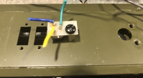
I'll finish this update with two photos. One is the original speaker. The other is the volume pot. Not sure how to wire this one, as it looks nothing like the one in the manual.
U4a.OriginalSpeakerU4a.VolumePot

Attachments

Images (6)
  • U4a - Tach Upgrade
  • U4a - Smoke Unit
  • U4a - Engine Wiring
  • U4a - Tender Sans Wiring
  • U4a - Original Speaker
  • U4a - Volume Pot

What do you use as a baffle?  Specifically, I see that it needs to be supported above the surface to avoid the cone from hitting the surface.

I use serving cups from Taco Bell for the Baffle. I cut part of the inner circle out of the bottom to let the magnet protrude through and trim a little off around the lip of the cup. In my photos, you can see a factory-applied foam layer on the base of the speaker. I do remove that now and seal everything with hot glue after soldering on the wire connection. I didn't put a baffle in the tender photos above and it does make a difference but the speaker alone in a relatively tight space sounds very good.

On the cone-facing side of the speaker, the mounting holes are recessed just a bit. I used standoffs that fit perfectly in the holes to mount the speaker. Two of the stand-offs mount the speaker to the frame and the other two balance rest flush with the frame. In some cases, I'll reuse the existing threaded holes to mount the stand-offs if everything lines up. I can post some additional pictures this evening.

I've got another update, although this one has no photos. I've mounted the board on the old heatsink as well as installed the proto-coupler. It's a little long, but I've always found some of the Weaver couplers to be a tad short. I can always replace it.

It's now time to do the wiring, and this is where I'm getting a little hung up. I'd like to re-use the existing volume pot, but I'm not sure which wires go to which terminal (see above.)
I'd also like to use the existing pickups on the tender for added power. Can I assume that the red & black wires on the included tether are positive and negative. I've read that MTH sometimes messes up the wiring in the tether.

Any help is appreciated!

You can always trace wires, but red and black in tether are AC going to 7 pin.  The color changes seem to be on the engine side with smoke and HL wire colors.  For the volume pot when gray and red in contact that is full volume.  Blue and Red is mute.  So turn pot one way and measure ohms between center and one side.  Wire accordingly.  G

It's time for another update!!
There has been significant progress.

First, I was able to wire up the volume pot and the speaker. The volume pot wasn't too difficult to wire once I figured out which colors were which. In this case, blue to blue, green to red, and yellow to grey.
Second I was able to wire the speaker up. MTH wasn't super clear in the instructions as to the polarity of the wires. In this case yellow is +, and white is -. That is not indicated anywhere in the manual.
The coupler proved to be more challenging than I had thought. Unfortunately, I had to separate the wires in order to fit them through the slot in the engine. If this was a larger frame, I would've drilled a bigger hole. However, as you can see below, I didn't have much space to work with. U4a.CouplerWiringjpg

The tender shell has a bar that sits over the two holes. The mounting holes for the shell are in that bar.  Thus, I was forced to use the pre-existing slit for the pickup and ground wires. Everything fit, except the connector. A little bit of wiring later, and it was fine!

Next came mounting the board. I was able to re-use the old board's mounting plate for the new board.
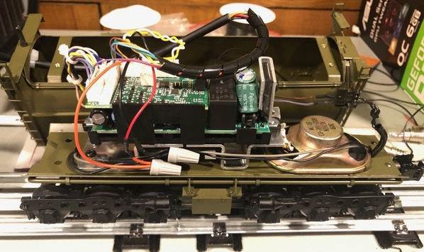
U4a.TenderFinish

After some fun re-wiring (I had to separate the one large pin plug from the tether via the purple wire) I was able to set everything up for the test.
The test was successful. The engine made noise, did all it's fun test tones, growled like a diesel, and moved and smoked just fine. I did some wiring cleanup and cable management, and then test fit the tender shell. At present, I am still using the stock lighting, as otherwise I would've sealed the shell.

Next came installing the custom sound file I had made for this engine. Given it's size, I used the an MTH PS3 N&W 4-8-4 J-Class engine as my sound file base. Many of MTH's PS3 Northerns are oil burners. This particular Canadian National Northern (Confederation in Canadian terms,) is a coal burner. In my experience with making custom MTH sound files (the U1f one was an adventure,) I've discovered its often times easier to find a base file that requires minimal tweaking. A whistle swap here, a bell swap there, changing out the compressor sounds over there, a complete redo of the PFA sequence, and it was finished.
Installed it on the engine, and viola, the engine was essentially finished. It made a few successful circuits around my test loop, and then I noticed that the chuffs weren't in sync with the drivers.

Here comes the fun. Pulling up the information in ADPCM, the J Sound file was able to spit out all the relevant information regarding it's speed curve, driver revolution, etc.
Measuring the U4A, I discovered a few interesting things.
First, the drivers are 38.6mm in diameter.
Second, a full revolution of the driver is 17 revolutions of the flywheel.

ADPCM will allow me to edit values within the file. Will entering the relevant numbers sync the chuffs? Am I thinking of gear ratio wrong? The J I'm fairly certain does not have the same gear tower this engine has.
I could care less about accurate SMPH, as I run the speed using the eye test. This engine will also never double-head, so again, SMPH doesn't need to be accurate here.
Attachments

Images (2)
  • U4a Coupler Slot & Wiring
  • U4a.TenderFinish

Add Reply

Post
The DCS Forum is sponsored by

OGR Publishing, Inc., 1310 Eastside Centre Ct, Suite 6, Mountain Home, AR 72653
800-980-OGRR (6477)
www.ogaugerr.com

×
×
×
×
Link copied to your clipboard.
×
×