


Maybe the red color will improve the operation of my home built projects? ![]()
It’s always worth a try!
We shall see if red helps, order just placed with SEEED. Now off to Digikey for more parts.
If nothing else, I'm helping with economic growth! ![]()
Just out of curiosity...
If this board was put on a car and wired to pickups on the truck, could it be used as a DCS signal check around the loop? Would a slightly more generous go/no go adjustment on the pot make it capable around a loop?
Following with great interest...
I actually have no real idea how well this would work, but I don't think this is all that appropriate for that use. The "signal strength measurement" around the layout with the DCS locomotive is just checking the percentage of error free vs sent packets are received. I would expect the actual signal to vary pretty widely on a layout and still be considered "good".
That's left as an experiment for the student. ![]()
eddiem posted:Just out of curiosity...
If this board was put on a car and wired to pickups on the truck, could it be used as a DCS signal check around the loop? Would a slightly more generous go/no go adjustment on the pot make it capable around a loop?
Following with great interest...
Adrian made a car in this thread - AGHR DCS Telemetry Train Rev 7 - that I believe checks the DCS signal around the track in a similar manner to the TIU Tester being discussed here. It is quite elaborate (over my head by a foot or two) and I believe costs quite a bit more, but it is a really nifty device.
I was thinking that the project in this thread may have come about from the thread link above, only as a less expensive test module? But I think, as GRJ said above this one was more for just testing at the TIU outputs and not the entire layout. At least that was my interpretation of it anyway? If I'm off a bit here, maybe Adrian or GRJ can set the record straight. I have also just been trying to follow along and keep up as best as I can.
rtr12 posted:eddiem posted:Just out of curiosity...
If this board was put on a car and wired to pickups on the truck, could it be used as a DCS signal check around the loop? Would a slightly more generous go/no go adjustment on the pot make it capable around a loop?
Following with great interest...
Adrian made a car in this thread - AGHR DCS Telemetry Train Rev 7 - that I believe checks the DCS signal around the track in a similar manner to the TIU Tester being discussed here. It is quite elaborate (over my head by a foot or two) and I believe costs quite a bit more, but it is a really nifty device.
I was thinking that the project in this thread may have come about from the thread link above, only as a less expensive test module? But I think, as GRJ said above this one was more for just testing at the TIU outputs and not the entire layout. At least that was my interpretation of it anyway? If I'm off a bit here, maybe Adrian or GRJ can set the record straight. I have also just been trying to follow along and keep up as best as I can.
Exactly!
An oscilloscope is the best debugging solution and shows you the DCS waveforms, voltages, distortion and noise,... and is a $500 solution. The telem train in the other thread is the $100-150 solution for those that want exact voltages and signal strength but not necessarily want to debug waveforms. This one is the $10-20 solution for those that just want to know if it's broken or not.
Speaking of the pricing, I have exactly six kits of parts with a PCB and all the parts, $15/ea shipped for the first six emails I get to my profile email address. I'm not going any farther with this, so I might as well let someone else have the fun of assembling them. ![]()
Adrian and GRJ,
Thanks for all the work you did on this project. I managed to put together a board that is similar to Adrian's initial version but also adds the self powered feature and a power indicator found in GRJ's final version. Here is a picture of the board and a quick video showing the blue led light up when I blow the whistle on one of my locomotives. The red light is just a power indicator.

I ordered the board that GRJ designed so I could put together one that looks a little more professional.
Attachments
Images (1)
Videos (1)

Your's looks great, John. I'm going to order the board John designed too. Kind of just for fun!
I have one kit left. ![]()
gunrunnerjohn posted:I have one kit left.
I’ll take it if no one beats me to it.
The circle is closed and all the kits are gone. ![]()
Hopefully someone is ordering boards from the files I posted if anyone else wants one of these.
GRJ,
I ordered 10 from SEEED (the pretty red ones like you had ![]() ) and parts for 10 units from Digikey. Still waiting for ordered items to arrive.
) and parts for 10 units from Digikey. Still waiting for ordered items to arrive.
If all goes well I would be willing to put together some kits or maybe even assemble a few for those that don't like soldering. If this batch goes well I might consider another batch if there is any more interest. I would not want anything extra, just enough to cover my expenses, so price be whatever the boards and parts cost me plus shipping. I have not shipped many things (I mostly just order stuff) so I would have to figure out what would be the best and least expensive method.
The only thing I haven't ordered are the alligator clips for connecting to the track or banana plugs to plug into TIU. I already have some for my own use, but I wasn't sure what anyone else might want for connections. These could also be left out and the end user could install the connection of their choice.
You're the Man, RTR!!
FWIW, I didn't so anything about the actual TIU connection as it could be several varieties. My "kits" were simply all the parts for the PCB.
GRJ, That sounds like an even better idea on the TIU connections. My thoughts exactly, what to put on there for a connection? In after thought a couple of screw terminals might be a good idea? Maybe for the next batch, if there is one?
Mark, Very kind words...thank you. ![]()
Well, the design files are up there, when you get used to Diptrace, you can put the terminal block on. ![]()
You're welcome RTR12! I took the easy way out and got the kit. I'll decide what type leads/connector to put on when I get to building it.
GRJ, I looked at the files when sending the order to SEEED. So far I'm stalling on butchering anything. I'll make a copy first, before I try it. ![]()
Mark, good luck with your kit. The first one I tried from OSHpark, I cut a couple of alligator jumpers in half for the leads. I think Stan suggested that earlier or in another thread. I used a 9v battery holder with on/off switch for the power, trying to be nice and neat. Guess what didn't work? The darn battery holder, 9v in and 0v out the output wires, figures...
![]()
I built mine up tonight Gunrunner. Seems to trigger green on some of the larger commands.
Now to try a few different older TIUs and see what happens with those. I've got one here that the track signal only gives about a 6 on the signal test - could be a good candidate to try out.
Thanks Gunrunner.
Jim
Adrain, John
Thanks for taking the time & effort in coming up with this DCS-TIU Port Tester tool. It is a quick and easy way the see if you are getting full DCS signal output from the TUI port. I tried the tool out on several TIUs and it works as intended. I will most likely first use the tool the check out a TIU port and use the scope if needed. TIU ports where I have a 14vpp signal, I have both Red & Green LEDs lit. Ports where I am in the 8-9 Vpp range, only the red LED is lit. <5-6 volt range, neither LED lights.
Thanks again guys,
Bob D
NJ-Hi Railers


Attachments
Images (2)
GRJ, after sending you an email, I saw above that you are sold out. Where on these 6 pages can I find the final schematic, or could you please post it again?
I'm not going to get involved with producing boards, which I guess is what the other two files you posted with the BOM are for. Any reason I can't just use breadboard and hardwiring, following your top view pictures and the schematic?
RJR posted:GRJ, after sending you an email, I saw above that you are sold out. Where on these 6 pages can I find the final schematic, or could you please post it again?
I'm not going to get involved with producing boards, which I guess is what the other two files you posted with the BOM are for. Any reason I can't just use breadboard and hardwiring, following your top view pictures and the schematic?
No reason you can't wire it on a perf board. OTOH, depending on how much you think your time is worth, you can have three PCB's for $13.60 from OSH Park. Sell a couple for $4-5 and build the other one up.
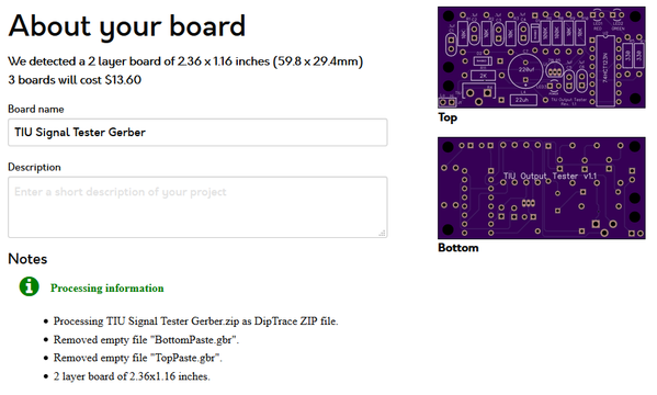
Here's the complete design archive, including the Schematic and the top view of the board. Also included are the Gerber files for ordering a board from OSH Park, the BOM for the parts, and the DIPTRACE files.
Attachments
Images (1)

Files (1)
Thanks, GRJ. Your post gives me a thought: anyone have one of these boards from OSH Park that they want to sell?
RTR mentions boards from SEEED. Are these identical?
GRJ, if that doesn't work, do I merely contact OSH Park by email, attaching your Gerber file, and they can then complete an order?
If you order boards from most anyone using those Gerber files and use the default of 1/16" thickness, you'll get the same board. As far as OSH Park, you simply establish an account there, and drag-n-drop the ZIP file containing the Gerber files on the upload block and follow your nose. Their defaults will give you the board required. SEEED Studio is similar, you just get more boards for your money.
Yes, the boards I ordered are identical to GRJ's. He created the files I used to order from. They are even red as in GRJ's picture above for the ones he ordered. I hope to have everything together by sometime next week, probably late in the week. Email me if you want a kit, email in profile, and I will add you to the list. I think I have 6 or 7 kits left. I only ordered enough boards for 10 kits, but I could order more if there is interest.
I have most of the parts, but I decided to order some terminal blocks to see if they would fit on the board, but the boards were ordered sometime prior to my thoughts here. I really don't expect them to fit? This was an after thought after thinking about one of GRJ's posts above. Probably better to revise board BEFORE trying to adapt terminal block, but thought it might be worth a try anyway...
Also as GRJ says, ordering from OSHPark is really easy too. And GRJ included a parts list with the Digikey part numbers on it already so that part should be pretty easy too. That is also what I used to order parts. I used the defaults GRJ mentions above to order the boards, but selected Red for the board color. I think OSHPark only has purple for colors, not certain on that though?
Should be no reason a .1" spacing connector won't fit in the two pin slot for the TIU connection. It's a standard 2.54mm (.1") spacing, and there's plenty of room around it for most connector styles.
Jim Sandman posted:I built mine up tonight Gunrunner. Seems to trigger green on some of the larger commands.
rad400 posted:...TIU ports where I have a 14vpp signal, I have both Red & Green LEDs lit. Ports where I am in the 8-9 Vpp range, only the red LED is lit. <5-6 volt range, neither LED lights.
Has someone posted instructions on how to calibrate a home-built unit - particularly without an oscilloscope? From scope photos earlier in the thread, measuring peak-to-peak amplitude of the funky-looking DCS-signal can introduce a calibration "error" of, say, 1-2 Volts.
As a simple Go/No-Go or Go/Maybe/No-Go tool perhaps this is not an issue and the instructions can be as simple as to set the trimpot to the mid-point angle (or whatever). Just asking. ![]()
Well, I started with a known good TIU, which I suppose can be a challenge for someone without a 'scope. I set the unit to trigger red and green on that signal. Then I used a cap across the TIU output to step on the signal until it was only around 8 volts and made sure that only the red light lit.
rtr12 posted:...I have most of the parts, but I decided to order some terminal blocks to see if they would fit on the board, but the boards were ordered sometime prior to my thoughts here. I really don't expect them to fit? This was an after thought after thinking about one of GRJ's posts above. Probably better to revise board BEFORE trying to adapt terminal block, but thought it might be worth a try anyway...
If by terminal block you mean the screw-terminal style like JOHNF showed in his hand-built unit, note that you can get 0.1" style for about a dime a piece on eBay. Note that on eBay listings, "2.54mm" is the operative search term (vs. 0.1"). If anything, looks like the trimpot might be a tad close in the left-to-right dimension?

Attachments
Images (1)

GRJ and Stan,
That is what I ordered, 2.54mm (0.1"). I looked at GRJ's drawings and info in the files posted. I just ordered a few from Digikey to see if they would work. They were not all the expensive, though ebay would be cheaper as Stan's picture shows. Nice to hear that you think there will be room for them. ![]()
Set up instructions for those of us without 'scopes' would be really nice to have too! If there is such a way?
Stan, GRJ,
Could this earlier post below from Ardian be a clue to calibration?
Adrian! posted:Dave45681 posted:Thanks for posting this!
So to set the trim pot, do we set it up on a TIU output we have reason to believe is good and just adjust the pot until the LED starts blinking? Or is there a better method during construction (maybe applying a DC signal directly to the B/C node of the circuit before installing the filters on the front end?)?
Thanks for all the good discussions you have been posting on the topic.
-Dave
Hey!
Yup, the trimpot just sets how many volts of dcs signal you need before the light flashes. If you turn it all the way up it’ll flash at 2.5V. In the middle it would flash at 5V. Near the top maybe 50V or more. I think it’s easiest to just tune it against a good channel like you suggest. Tune it to the point right where it barely flashes on a working channel, then leave it set there as your threshold of good and bad for future tests.
Stan & GRJ,
Another possible clue from Adrian, maybe? He also mentions changing to 10k resistor and 100nf cap in one spot.
Adrian! posted:Here's how mine looks.
After more playing around side-by-side with the scope I suggest a shorter time base so you can see long gaps between packets like the one in the video (10K and 100nF). I don't have a pot handy so I used a 3K and 1K resistor for the divider.
Just thinking this might help some of us in the less knowledgeable category here. I know what he means about the R & C changes, but others may not? I asked Adrian about this earlier in the thread (near this post, I think) and he confirmed what I was thinking here about the RC changes.
In general, the calibration "problem" is the accuracy, quality, etc. of the measurement reference or standard. The idea of using a "known good" TIU output as the reference is no doubt the most practical...but what does "known good" mean?!
As Adrian pointed out elsewhere, you can get 10's using the DCS signal quality test with signal levels of only 3-4 Volts. Yet, if the signal level is only 3-4 Volts, you certainly have a degraded TIU channel and ought to change/upgrade the internal electronics.
Adrian did the heavy-lifting with his original post in this thread and demonstrated the concept with components he had on hand. I think you need to focus on the latest incarnation of the design as that's what you're apparently building and offering to other members.
If you don't have a scope to verify that a "known good" reference signal is indeed 14V peak-to-peak (or whatever), I'm thinking you could use a 12V DC voltage (or even a 9V battery) to serve as a low-cost DC "reference" voltage for the express purpose of getting you in the ballpark (within, say, 20%) which ought to be good enough for a simple tester. The idea would be to inject this DC voltage into the trimpot.
Thanks for the good ideas here, Stan! I am not sure my TIU has a 'known good reference' channel, but the 12vdc I have plenty of, also 9v batteries. I built one board from the original design (OSHPark), but have yet to get any reading from it (hoping it was something I did wrong). Although my layout still runs everything with no problems or DCS errors?
Hopefully I can try this out next week sometime if the new boards arrive by then. The new boards are from GRJ's latest design files and he has assembled and tested one of those already. Really hoping my TIU provides a good reading this time! ![]()
Here's one minimalist approach to "calibration" - no scope, no battery, no other components required! This uses the relatively accurate on-board 5V voltage as a reference.

With the 2 LED method (vs. original 1 LED method), there are 3 "zones". (1) BOTH LEDs blink meaning good signal level, (2) 1 LED blinks meaning marginal/degraded signal, (3) Neither LED blinks meaning very low or no signal.
1. Apply AC track voltage to module. Presumably the "Power" LED turns on. Use DC voltmeter to confirm you have 5.0V DC at the point indicated. The DC- side of the DC measurement is the circuit ground.
2. By momentarily touching +5V to the DC+ point as shown (using, say, an alligator jumper cable), you are effectively applying a 5V trigger. By turning the trimpot fully in one direction, you should be able to make BOTH LEDs flash each time you tap +5V to the DC+ point. By turning the trimpot fully in the other direction, you should not be able to make either LED flash. The idea is to adjust the trimpot to the case where you're at the threshold between NEITHER LED flashing and 1 LED flashing. To be clear, this is a separate threshold than between 1 LED flashing and BOTH LEDs flashing.
This simple (?) procedure "calibrates" the unit to flash both LEDs on a 10V DCS signal. This is probably good enough IMO but to each his own.
3. If you have access to a "known good" TIU channel, it will surely trigger BOTH LEDs as it appears you get more than a 10V DCS signal. You can then further adjust the trimpot with the "known good" TIU knowing that you have AT LEAST a 10V output. To do this, you then send a real DCS signal out the TIU and adjust the trimpot to the point where 1 LED flashes and BOTH LEDs flash.
Attachments
Images (1)

Interesting approach Stan, and it does have the virtue of being really simple.
Stan,
Thank you for the additional info above! I printed all of it so it will be handy for testing. Maybe I will go back and fiddle with the original board while I am waiting on the newer ones.
I got my boards from OSHPark, and the port tester works perfectly. I'm a beginner at assembling circuit boards, and at first I wasn't sure about the orientation of the LEDs. I followed the traces on the board and figured out that the negative lead of the LED goes in the hole with the square pad. Here is a picture of the fully assembled board:

Attachments
Images (1)
Looks good, I like your banana plugs.
To all that emailed me about a kit, please check your email. Everything has arrived and is about ready for shipping out.
If anyone else wants a kit I have 4 left. They are $17.00 each, that includes shipping. Email is in my profile.
rtr12 posted:To all that emailed me about a kit, please check your email. Everything has arrived and is about ready for shipping out.
If anyone else wants a kit I have 4 left. They are $17.00 each, that includes shipping. Email is in my profile.
I'd like one. email sent.
I'd like one too. Email sent.
There were a couple of questions about which PCBs I have. They are exactly like the Red ones GRJ posted earlier in this thread as his finished tester board (the newest revision). The parts are exactly what GRJ posted in the BOM for the PCBs. I added to the list a socket for the 74HCT123N and a two position terminal block so you could easily connect the wire/connectors of your choice to connect to your track, TIU, etc. or easily swap leads if you want to.
Also Stan2004 posted some good tips earlier in this thread on how to calibrate the testers.
Here are some pictures that may help.


Attachments
Images (3)
Looks great John F and RTR. I have one of the GRJ kits, but must confess I haven't had time to build it yet. I've been spending too much time at my elderly parents' empty house mowing, doing roof and gutter maintenance, and some electrical upgrades.
Maybe the electrical upgrades count for something on an OGR electrical topic. I shudder when I see some of the wiring in this 130-year old house!!! I never dreamed the remaining knob and tube wiring was still live!! Well, it isn't any more!
Mark, I remember my parents' 1927 house, that the insulation on the BX cable would crumble when replacing a receptacle, and no green cable.

JOHNF points this out earlier, but white printed "silkscreen" should show "flat" side of the 3 LEDs on the square pad as shown in hand-edited photo above. Additionally, the large capacitor C7 must be installed with white stripe ("-" side) as shown.
Attachments
Images (1)
RJR posted:Mark, I remember my parents' 1927 house, that the insulation on the BX cable would crumble when replacing a receptacle, and no green cable.
You got that right!!!
email sent on kit
Thanks Stan! I added a note to the BOM I included with the kits about the LEDs, but you added a lot more help here that I hadn't thought about, especially for those of us less knowledgeable around here. And also all the calibration info you posted above.
I'm out of kits from the current batch, but I have 4 orders toward the next batch. The boards are ordered in lots of 10.
If anyone else is interested, send and me an email (it's in my profile). When we have enough orders I will place the next PCB order and let you all know.
For the first batch, I have emailed everyone payment info and asking for their shipping info.
I've since found that I could use a 5mm LED footprint and get the proper flat represented, you can still pop a 3mm LED in the holes. In the actual silkscreen of the 3mm LED part the holes break up the silkscreen and that part doesn't make it to the board. However, I should have just used the 5mm part, the hole spacing is the same and it would have made it clearer.

Attachments
Images (1)

Hey RTR12, I just emailed you. I'd like one!
Thanks,
Got it. You're on the list for the next batch.
Here's another picture of all the contents in the kits. I marked all the resistors and a couple of other things. I think the rest should all match the PCB layout markings and hole layouts. Hope it's all clear enough for everyone.

Attachments
Images (1)
RTR12, please put me in for 2 kits.
Got it Dave, but please send me an email so I can keep track of who ordered what, I'm sure I will miss something trying to keep up with the thread here. Much easier for me to track emails.
Thanks!
You're going the extra mile with the kits, very meticulous! ![]()
Thanks, GRJ!! It was originally self serving, then I thought others might like it too. Stan got me thinking about the markings, from the added details he posted above. (my packaging and shipping still needs some refining)
And thanks to you, Adrian and Stan for making it all possible!! These are pretty neat little devices. ![]()
The one thing to make clear with the kits is the orientation of the LED's, the 3mm pattern I used didn't show the flat on the LED. In all three cases the short (negative) lead goes to the square pad. You might mention the diode polarity as well...
I included a parts list with a note at the bottom about the LED orientation. But I didn't note anything else. Then Stan posted above about all the other things so I didn't add those to the list. I will do that for the next batch of kits. I was going to try and fix the PCBs as you described above, but they went so fast I ordered more before trying to make the adjustment.
My color printer shot craps or I would include one of Stan's detailed pictures on the list. All I have at the moment is a B/W laser printer. Guess I'll try it with that and see how it looks. Probably not too good, won't show the pretty red boards... I was looking at some color lasers, but haven't found one that doesn't need $300-$400 worth of toner when it runs out. Nearly double the cost of a 'home sized' printer! Maybe ink jets weren't so bad?
Batch 2 is sold out. Parts are on order, 3 weeks or so for the PCBs.
I would be happy to do a 3rd batch if there is interest. We need 7-8 orders before ordering the PCBs and parts.
To everyone from the 1st batch, your kits went to the post office this morning.
RTR12, the TIU tester kit arrived today. Thanks. I see that the postage was $3.50, not the $3 you estimated. When you send me info on the price for the TIU protection kits, I'll add the 50 cents.
Thanks, RJR, but I got the envelopes for a little less than I figured so I am good! I figured $1 ea. and they were only about 50 cents each in packs of 6. Tried to use online shipping at USPS, but it didn't seem to like the envelope shipping unless you used priority mail which was like $6.70 or something like that. As you can see, I don't ship much. ![]()
Hope you got all the correct parts and the kit all goes together smoothly. You probably know this already, but see the posts above here from Stan, on the correct orientation of some of the parts that could be installed improperly.
Tom, you need to discover https://www.paypal.com/shipnow
You can generate first class postage and print it on half-sheet labels. I believe up to around 4 ounces, it's $2.66 for shipping. I use tons of padded envelopes with this service. Of course, I bought the envelopes in a lot of 250, and they were less than $24, so that's around 10 cents apiece. It doesn't take long to break even if you're paying 50 cents each. ![]() I also buy the half-page labels in bulk to save money as well.
I also buy the half-page labels in bulk to save money as well.
Thanks GRJ,
I'll check out the Paypal shipping, wasn't aware of that before. The $2.66 is what the USPS online said, but wouldn't let me use it online. That's when I took one to the PO to be sure, they then said it was $3.50. I guess they considered it a 'Package' and not an envelope so I didn't want to take chances. About a week ago I got a rate sheet from the PO and it said it was even less than $2.66.
As for the envelopes I didn't think I would need all that many? But maybe you have a point as we are on the 3rd batch of these now. 250 is a lot for me though, as I really don't ship all that much other than these things. Most things are 'ship to me' and not me to someone else. PO had some nice small boxes, but they were over $2 each, $2.19 or maybe $2.49 even, nice and perfect size, but a wee bit steep $$$.
You can get smaller quantities and pay a lot less than 50 cents. US suppliers, so shipping won't be more than about a week. Here's one of many, 24 cents each for 25 of them.

Attachments
Images (1)

I have enough envelopes for the next two batches, but I may try the ones you posted here and see what happens. When I got the ones I have now, I hadn't really thought about shipping until all the parts were here and things were ready to go. Then, oh dear, what am I gonna put these in? Spur of the moment thing... Once I get everything streamlined I'll probably never have anything to ship again. ![]()
I looked at the Paypal and I think I'll try it for the next batch. I'll do a dry run with one just to see what it costs and go from there. They ship UPS too, that's nice for bigger things. I suppose they would have to, but I presume the USPS will accept the Paypal rates without any problems? Sure beats stamps! ![]()
Also. I guess you use full sheet labels with the sticky on the back? I have a bunch of labels left over from when we moved a few years ago, but they are like 2" x 4" or so and I don't think the printer will like those. Don't think I've printed a label since I had a dot matrix printer...Used to print labels for 5.25" floppies back in the day.
The postage labels you want for printing ebay/PayPal postage are the half-sheet gummed labels.
I didn't think what I had would work in the printer. I will do some more looking around. It will be at least 3 weeks or so for next PCBs get here. Thanks for all the tips here, it's appreciated!
Gotta' get you shipping those kits. ![]()
You will make a great hobby supplier, RTR12!!!!
You are at least streamlining the operation a bit here! I got some labels coming to try the Paypal shipping.
Mark, I wish I had the smarts to think these things up on my own. But, just putting these things together (from the work of others) is still kind of fun and it keeps me off the streets! I may change my tune after about 50 or so...![]()
The neat thing about the Paypal method per GRJ is when entering the recipients address to print the label, you can also enter an email address. This way the recipient gets an email with the tracking number; both parties can click to see package progress. This is USPS First Class "Package" service so you can use thicker padded envelopes to protect the components. I believe there is a thickness limitation on basic envelope service of 1/4" of something like that so you couldn't use the less expensive envelope rates anyway (which also don't include tracking #).
If shipping just the raw board without parts (which would be less than 1/4" and less than 1 oz.) you could use just an envelope and pay the non-machinable surcharge since the stiff board can't bend thru USPS sorting machines. I think with surcharge it's like 75 cents and there's even the butterfly stamp for that purpose. But unlike package service, no tracking #.

Perhaps obvious but after printing the label at home with the bar-code tracking number, you can drop it any mailbox (don't need to go to PO).
Attachments
Images (1)
I've been using PP for years to ship, it's much more convenient to print stuff at home, and if you have any Priority shipments, they'll even pick it up at your door! ![]()
Thanks Stan, more good info. According to the rate sheet they gave me, it is 1/4" thickness for letters and 3/4" for the larger envelopes. But their rates were more when I took the first kit up to the PO to make sure I was using the correct postage. I didn't know about the special non-machinable stamps either? You guys are way ahead of me on this stuff!
The PP service looks neat and the tracking email sounds really nice too. I am going to try it on the next batch of kits. You can learn all kinds things around here! As for the mail box, I think the closest one is at the PO. We have those nifty community mailboxes spotted around the neighborhood. They have an out slot, but it's only about a 1/4" to 1/2" opening. Probably not enough for kits to fit in.
I received my kit from RTR12, and was surprised at the small size of the traces. Which piques my curiosity: When sending a files for production of a board, do you specify the necessary ampacity of the traces?
They're only carrying signals, the total current all over the board isn't more than 40-50 milliamps!
As for the boards, you specify the copper weight and the trace width. You can also pick specific nets and have different trace widths. Many times, I'll go for heavier traces for ground and power traces, for instance. In the case of this board, that was totally noncritical, so I just went with a nominal trace width of .012" and 1oz copper.
Just FYI, that trace width is good for 1 amp for external layers for a 3 inch trace. In other words, way more than sufficient for anything on the board.
Thanks, John, for the education. I appreciate it.
RJR, also the PCBs are always smaller than I expect, when you get them in hand.
Wait til you see the SMT PCBs! Sure hope I can find them in the packaging...![]()
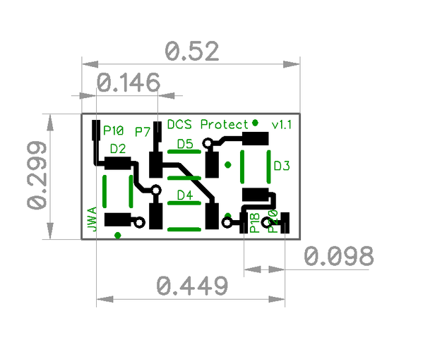
What do you mean Tom, they're huge! Over half an inch long and nearly .3" wide. ![]()
![]()
Attachments
Images (1)

Hmmm... I guess they are slightly larger than I was thinking, somewhat seeable at least. Can't wait to try the soldering part and trying to find the SMT components. ![]()
Just don't drop the resistors on a white floor. If they land upside down, you'll never find them, the white ceramic back blends right in! ![]()
The blue LEDs do that too! ![]() I have one missing here on the concrete basement floor, kind of white/light gray. Need to get my grandson over to find that one. I will watch out for the resistors, very carefully. I will probably be able to lose those resistors right on the workbench!
I have one missing here on the concrete basement floor, kind of white/light gray. Need to get my grandson over to find that one. I will watch out for the resistors, very carefully. I will probably be able to lose those resistors right on the workbench! ![]()
I hate to do this to you guys...… ![]()

I too have built it.... well, I have to plug in that main chip thing. Then I'll put it into one of my spare small project boxes to help it last.
I have to tune it. So now I need to go back and find the instructions on how to tune it up!
I read them here but like so many others that have replied, we've pushed the good stuff into the lost pile.
& Thank you Tom for the great kit..... (off to see if it works!)
Attachments
Images (1)
stan2004 posted:Here's one minimalist approach to "calibration" - no scope, no battery, no other components required! This uses the relatively accurate on-board 5V voltage as a reference.
With the 2 LED method (vs. original 1 LED method), there are 3 "zones". (1) BOTH LEDs blink meaning good signal level, (2) 1 LED blinks meaning marginal/degraded signal, (3) Neither LED blinks meaning very low or no signal.
1. Apply AC track voltage to module. Presumably the "Power" LED turns on. Use DC voltmeter to confirm you have 5.0V DC at the point indicated. The DC- side of the DC measurement is the circuit ground.
2. By momentarily touching +5V to the DC+ point as shown (using, say, an alligator jumper cable), you are effectively applying a 5V trigger. By turning the trimpot fully in one direction, you should be able to make BOTH LEDs flash each time you tap +5V to the DC+ point. By turning the trimpot fully in the other direction, you should not be able to make either LED flash. The idea is to adjust the trimpot to the case where you're at the threshold between NEITHER LED flashing and 1 LED flashing. To be clear, this is a separate threshold than between 1 LED flashing and BOTH LEDs flashing.
This simple (?) procedure "calibrates" the unit to flash both LEDs on a 10V DCS signal. This is probably good enough IMO but to each his own.
3. If you have access to a "known good" TIU channel, it will surely trigger BOTH LEDs as it appears you get more than a 10V DCS signal. You can then further adjust the trimpot with the "known good" TIU knowing that you have AT LEAST a 10V output. To do this, you then send a real DCS signal out the TIU and adjust the trimpot to the point where 1 LED flashes and BOTH LEDs flash.
here's what I need!
Just to be sure, the schematic does match Tom's board, right?
So the stripe on the diode at D1 to the R4 designation on the board at the pot?
Joe,
That looks great! GRJ and Stan have been further educating me here too (I'm a bit green on kit mailings). I am going to ask Stan if he minds me including his instructions and his picture showing component orientation in with the parts list. Also, you are most welcome, it's kind of fun. Hope it works out well for you and all your TIUs are healthy! (at least it looks like you got all the parts and they are still intact ![]() )
)
Engineer-Joe posted:stan2004 posted:Here's one minimalist approach to "calibration" - no scope, no battery, no other components required! This uses the relatively accurate on-board 5V voltage as a reference.
With the 2 LED method (vs. original 1 LED method), there are 3 "zones". (1) BOTH LEDs blink meaning good signal level, (2) 1 LED blinks meaning marginal/degraded signal, (3) Neither LED blinks meaning very low or no signal.
1. Apply AC track voltage to module. Presumably the "Power" LED turns on. Use DC voltmeter to confirm you have 5.0V DC at the point indicated. The DC- side of the DC measurement is the circuit ground.
2. By momentarily touching +5V to the DC+ point as shown (using, say, an alligator jumper cable), you are effectively applying a 5V trigger. By turning the trimpot fully in one direction, you should be able to make BOTH LEDs flash each time you tap +5V to the DC+ point. By turning the trimpot fully in the other direction, you should not be able to make either LED flash. The idea is to adjust the trimpot to the case where you're at the threshold between NEITHER LED flashing and 1 LED flashing. To be clear, this is a separate threshold than between 1 LED flashing and BOTH LEDs flashing.
This simple (?) procedure "calibrates" the unit to flash both LEDs on a 10V DCS signal. This is probably good enough IMO but to each his own.
3. If you have access to a "known good" TIU channel, it will surely trigger BOTH LEDs as it appears you get more than a 10V DCS signal. You can then further adjust the trimpot with the "known good" TIU knowing that you have AT LEAST a 10V output. To do this, you then send a real DCS signal out the TIU and adjust the trimpot to the point where 1 LED flashes and BOTH LEDs flash.
here's what I need!
Just to be sure, the schematic does match Tom's board, right?
So the stripe on the diode at D1 to the R4 designation on the board at the pot?
That's the current schematic and it should match any of the boards I did or all the ones that Tom has shipped. AFAIK, no changes have been made to my design since I posted the final version and bought the first ten boards.
Thanks GRJ. No disrespect on who's boards was meant.
Thanks Tom, it was a fun kit to put together.
===
1. Apply AC track voltage to module. Presumably the "Power" LED turns on. Use DC voltmeter to confirm you have 5.0V DC at the point indicated. The DC- side of the DC measurement is the circuit ground.
===
"AC Track voltage" means hook 18VAC up to the test board?
rtr12 posted:...I am going to ask Stan if he minds me including his instructions and his picture showing component orientation in with the parts list.
Anything you think would help is fine by me.
swise posted:… "AC Track voltage" means hook 18VAC up to the test board?
Yup.
Engineer-Joe posted:Thanks GRJ. No disrespect on who's boards was meant.
None taken, I was just clarifying that my original schematic is good for any boards currently in circulation. ![]()
Ok, I received my kit and build it. I am a little confused with Stan's calibration procedure. At the end he states with a good tiu adjust trim pot unit one LED flashes and BOTH Flash? What does that mean? I ASSUME it means you want to turn the pot Clockwise until the Green LED no longer flashes, and then back off some until it just begin to flash again with a known good TIU. This would mean anything less than the good TIU value would not flash the Green LED.
Also is the Pot a linear function on adjustment. For example, I have my good TIU with the POT flat around 1 O'clock. I can measure that resistance value. If I have a TIU that is at 11 O'clock to get both, can I use the resistance to figure out how much the signal is degraded via a ratio? Or is this a non linear function? Thanks to all that contributed to this. G
PS For my good TIU which is my bench SF Loader only, have only used Fix1 and it is a REV L, it turns out both Fix 1 and Fix2 have the exact same pot setting to get the green to light. Fix2 has never been used.
I would suggest to the people assembling this board to add some hot melt behind the pot to hold it firm. Mine bent over while trying to adjust it. I imagine the way it's shaped means it works better with certain screw tips?
I put it into a case so that I can take it outside easily.
I also didn't fully know how to calibrate so I did exactly the way G described above. We think the same!
Edit: BTW I think mine ended up around 11:00? I considered adding a momentary switch to jump the 5 volts for calibrating. What do you think??
I'm not sure what a known good channel would be around here! ![]() I think all mine are good but I haven't tested yet.
I think all mine are good but I haven't tested yet.
Edit#2: test used Channel 1 of the Z4000, connected to channel #1 Fixed on TIU #1, aux AC power wall wart connected to TIU.
Joe,
GRJ is correct, no changes have been made to his last original post above, of the TIU Tester schematics, PCB files and components. Nice video Joe! Looks like you are up and running.
Also, For everyone still on the list for a kit, the next couple batches of PCBs/kits will be the same as all have been so far. No changes.
Stan,
Thank You. As usual you have been a lot of help here.
GGG,
I haven't tried the calibration yet, just checked mine to see if it worked and it did. I have a big mess to clean up on my bench (part sorting with no previous place to put them) and I have been goofing off the last couple days. ![]() I imagine (hope) Stan will be back by to assist, he knows a lot more about it than I do as well.
I imagine (hope) Stan will be back by to assist, he knows a lot more about it than I do as well.
GGG posted:Ok, I received my kit and build it. I am a little confused with Stan's calibration procedure. At the end he states with a good tiu adjust trim pot unit one LED flashes and BOTH Flash? What does that mean? I ASSUME it means you want to turn the pot Clockwise until the Green LED no longer flashes, and then back off some until it just begin to flash again with a known good TIU. This would mean anything less than the good TIU value would not flash the Green LED.
Correct. The red LED should flash in each case. The earlier steps calibrate the green to trigger at 10V. The end step is to fine-tune to something more than 10V from a "known good" TIU channel which supposedly puts out a bit more.
GGG posted:...
Also is the Pot a linear function on adjustment. For example, I have my good TIU with the POT flat around 1 O'clock. I can measure that resistance value. If I have a TIU that is at 11 O'clock to get both, can I use the resistance to figure out how much the signal is degraded via a ratio? Or is this a non linear function?
The pot itself has a linear taper (vs. logarithmic/audio taper) so the resistance changes at a fixed rate. The math gets a bit complicated to do what I think you're inquiring about. But in a small region - like between 11 o'clock and 1 o'clock for example, I suppose you could make a table of Volts vs. Pot angle (or measured resistance).
Not having a unit, my opinion though is the ability to discern a threshold based on the flicker or flashing behavior is very subjective. I'd guess this alone could introduce 1 Volt or more of "error" in interpreting the result.
Engineer-Joe posted:...
Edit: BTW I think mine ended up around 11:00? I considered adding a momentary switch to jump the 5 volts for calibrating. What do you think??
Once calibrated you shouldn't have to touch the pot again given the intended go-maybe-no-go application. If you want to experiment with turning the pot to a different angle as a method to measure a slowly degrading voltage (like GGG is pondering), I suppose a momentary push-button would be a simple way to reset the threshold back to 10V.
The problem with hard and fast pot positions was covered by Stan a long time ago. The variability of the triggering of the 123 chip is significant, and it's trigger point is a key factor in the calibration. AAMMF, it's the reason for needing a calibration!
When we did the red/green indicator on the DM TMCC Buffer, we used 1% resistors and comparators. That gives you a repeatable (within a couple percent) trip point for the various indications. If this little board had used similar technology, it would not need calibration. However, in that case, it would have required more parts, something that was not desirable. ![]()
Add Reply
Sign In To Reply
